2010 NISSAN TIIDA Drive belt replacement
[x] Cancel search: Drive belt replacementPage 2533 of 3745
![NISSAN TIIDA 2010 Service Repair Manual EM-174
< SERVICE INFORMATION >[MR18DE]
CAMSHAFT
4. Clean the mating area of intake valve timing control solenoid
valve. Insert a clean shop cloth (with no oil adhesion) into the oil
hole (A) of the cy](/manual-img/5/57397/w960_57397-2532.png "NISSAN TIIDA 2010 Service Repair Manual EM-174
< SERVICE INFORMATION >[MR18DE]
CAMSHAFT
4. Clean the mating area of intake valve timing control solenoid
valve. Insert a clean shop cloth (with no oil adhesion) into the oil
hole (A) of the cy")
EM-174
< SERVICE INFORMATION >[MR18DE]
CAMSHAFT
4. Clean the mating area of intake valve timing control solenoid
valve. Insert a clean shop cloth (with no oil adhesion) into the oil
hole (A) of the cylinder head.
5. Install engine mounting bracket (RH), engine mounting insulator, and torque rod (RH) under the Step 4 condition. (With intake
valve timing control solenoid valve removed, and a shop cloth
inserted into the oil hole.) Refer to EM-191, "
Component".
6. Crank engine, and then make sure that engine oil comes out from intake valve timing control solenoid valve hole (A). End cranking after checking.
• Check engine oil leakage by oil amount adhered to the shop cloth inserted into the oil hole.
WARNING:
• Be careful not to touch rotating parts (drive be lts, idler pulley, and crankshaft pulley, etc.).
• Prevent splashing by using a shop cloth so as to prevent the worker from injury from engine oil
and so as to prevent engi ne oil contamination.
CAUTION:
• Do not perform cranking without installing right engine mount bracket, right engine mount insu-
lator, and right torque rod.
• Prevent splashing by using a shop cloth so as to prevent engine oil from being splashed to
engine and vehicle. Especially, be careful not to apply engine oil to rubber parts of drive belts,
engine mounting insulator, etc. Wipe engi ne oil off immediately if it is splashed.
7. Perform the following inspection if engine oil does not come out from intake valve timing control solenoid valve oil hole of the cylinder head.
• Remove oil filter (for intake valve timing control), and then clean it. Refer to EM-195, "
Component".
• Clean oil groove between oil strainer and intake valve timing control solenoid valve. Refer to LU-16
.
8. Remove components between intake valve timing c ontrol solenoid valve and camshaft sprocket (INT),
and then check each oil groove for clogging.
• Clean oil groove if necessary. Refer to LU-16
.
9. Installation of the remaining components is in the reverse order of removal
Valve ClearanceINFOID:0000000005398133
INSPECTION
Perform inspection as follows after removal, installation or replacement of camshaft or valve-related parts, or if
there is unusual engine conditions regarding valve clearance.
1. Remove rocker cover. Refer to EM-149
.
2. Measure the valve clearance with the following procedure:
a. Set No. 1 cylinder at TDC of its compression stroke. • Rotate crankshaft pulley (1) clockwise and align TDC mark (no paint) (B) to timing indicator (A) on front
cover.
1 : Front cover
:Vehicle front
WBIA0781E
C : White paint mark (Not use for service)
PBIC3960E
Revision: January 20102010 Versa
Page 3617 of 3745
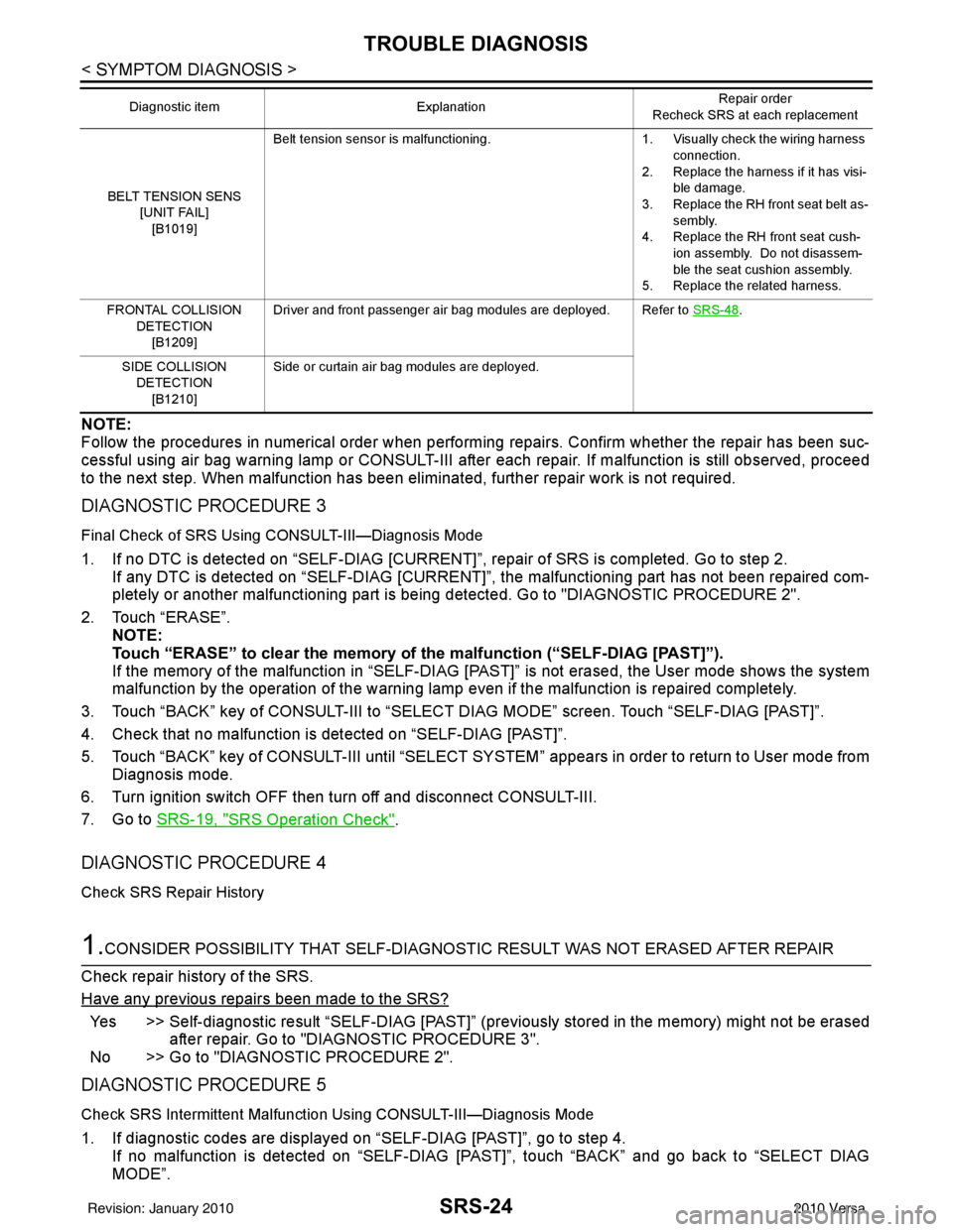
SRS-24
< SYMPTOM DIAGNOSIS >
TROUBLE DIAGNOSIS
NOTE:
Follow the procedures in numerical order when performing repairs. Confirm whether the repair has been suc-
cessful using air bag warning lamp or CONSULT-III after each repair. If malfunction is still observed, proceed
to the next step. When malfunction has been elimi nated, further repair work is not required.
DIAGNOSTIC PROCEDURE 3
Final Check of SRS Using CONSULT-III—Diagnosis Mode
1. If no DTC is detected on “SELF-DIAG [CURRENT]”, repair of SRS is completed. Go to step 2.
If any DTC is detected on “SELF-DIAG [CURRENT]” , the malfunctioning part has not been repaired com-
pletely or another malfunctioning part is being detected. Go to "DIAGNOSTIC PROCEDURE 2".
2. Touch “ERASE”. NOTE:
Touch “ERASE” to clear the memory of the malfunction (“SELF-DIAG [PAST]”).
If the memory of the malfunction in “SELF-DIAG [P AST]” is not erased, the User mode shows the system
malfunction by the operation of the warning lamp even if the malfunction is repaired completely.
3. Touch “BACK” key of CONSULT-III to “SELECT DIAG MODE” screen. Touch “SELF-DIAG [PAST]”.
4. Check that no malfunction is detected on “SELF-DIAG [PAST]”.
5. Touch “BACK” key of CONSULT-III until “SELECT SY STEM” appears in order to return to User mode from
Diagnosis mode.
6. Turn ignition switch OFF then turn off and disconnect CONSULT-III.
7. Go to SRS-19, "
SRS Operation Check".
DIAGNOSTIC PROCEDURE 4
Check SRS Repair History
1.CONSIDER POSSIBILITY THAT SELF-DIAGNOSTIC RESULT WAS NOT ERASED AFTER REPAIR
Check repair history of the SRS.
Have any previous repairs been made to the SRS?
Yes >> Self-diagnostic result “SELF-DIAG [PAST]” (pre viously stored in the memory) might not be erased
after repair. Go to "DIAGNOSTIC PROCEDURE 3".
No >> Go to "DIAGNOSTIC PROCEDURE 2".
DIAGNOSTIC PROCEDURE 5
Check SRS Intermittent Malfuncti on Using CONSULT-III—Diagnosis Mode
1. If diagnostic codes are displayed on “SELF-DIAG [PAST]”, go to step 4.
If no malfunction is detected on “SELF-DIAG [PAS T]”, touch “BACK” and go back to “SELECT DIAG
MODE”.
BELT TENSION SENS
[UNIT FAIL]
[B1019] Belt tension sensor is malfunctioning.
1. Visually check the wiring harness
connection.
2. Replace the harness if it has visi- ble damage.
3. Replace the RH front seat belt as- sembly.
4. Replace the RH front seat cush-
ion assembly. Do not disassem-
ble the seat cushion assembly.
5. Replace the related harness.
FRONTAL COLLISION DETECTION[B1209] Driver and front passenger air bag modules are deployed. Refer to
SRS-48
.
SIDE COLLISION DETECTION
[B1210] Side or curtain air bag modules are deployed.
Diagnostic item
Explanation Repair order
Recheck SRS at each replacement
Revision: January 20102010 Versa
Page 3621 of 3745

SRS-28
< SYMPTOM DIAGNOSIS >
TROUBLE DIAGNOSIS
NOTE:
Follow the procedures in numerical order when performing repairs. Confirm whether the repair has been suc-
cessful using air bag warning lamp or CONSULT-III after each repair. If malfunction is still observed, proceed
to the next step. When malfunction has been elimi nated, further repair work is not required.
Trouble Diagnosis without CONSULT-IIIINFOID:0000000005396911
DIAGNOSTIC PROCEDURE 6
Inspect SRS Malfunction Using "AIR BAG" Warning Lamp—Diagnosis Mode
NOTE:
SRS will not enter Diagnosis mode if no malfunction is detected in User mode.
1. Turn ignition switch ON.
2. After “AIR BAG” warning lamp lights for 7 seconds, turn ignition switch OFF within 1 second.
3. Wait more than 3 seconds.
4. Repeat steps 1 to 3 two times.
5. Turn ignition switch ON.
SRS is now in Diagnosis mode.
"AIR BAG" warning lamp operates in Diagnosis mode according to the Warning Lamp Flash Code Chart:
OCCUPANT SENS C/U [COMM FAIL]
[B1022] Communication between the occupant classification system
control unit and air bag diagnosis sensor unit is interrupted.
1. Visually check the wiring harness
connection.
2. Replace the harness if it has visi- ble damage.
3. Replace RH front seat cushion/ occupant classification system
control unit assembly.
4. Replace the air bag diagnosis sensor unit.
5. Replace the related harness.
OCCUPANT SENS [UNIT FAIL][B1018] Occupant classification sensor is malfunctioning.
1. Replace RH front seat cushion/
occupant classification system
control unit assembly.
BELT TENSION SENS [UNIT FAIL]
[B1019] Belt tension sensor is malfunctioning.
1. Visually check the wiring harness
connection.
2. Replace the harness if it has visi- ble damage.
3. Replace RH front seat belt as-
sembly.
4. Replace RH front seat cushion/ occupant classification system
control unit assembly.
PASS A/B INDCTR CKT [B1023] Front passenger air bag off indicator is malfunctioning. 1. Visually check the wiring harness
connection.
2. Replace the harness if it has visi-
ble damage.
3. Replace front passenger air bag off indicator.
4. Replace the air bag diagnosis sensor unit.
5. Replace the related harness.
FRONTAL COLLISION DETECTION[B1209] Driver and front passenger air bag modules are deployed. Refer to
SRS-48
.
SIDE COLLISION DETECTION
[B1210] Side or curtain air bag modules are deployed.
Diagnostic item
Explanation Repair order
Recheck SRS at each replacement
Revision: January 20102010 Versa