2010 NISSAN TIIDA WIRING
[x] Cancel search: WIRINGPage 3306 of 3745

TROUBLE DIAGNOSISMTC-27
< SERVICE INFORMATION >
C
DE
F
G H
I
K L
M A
B
MTC
N
O P
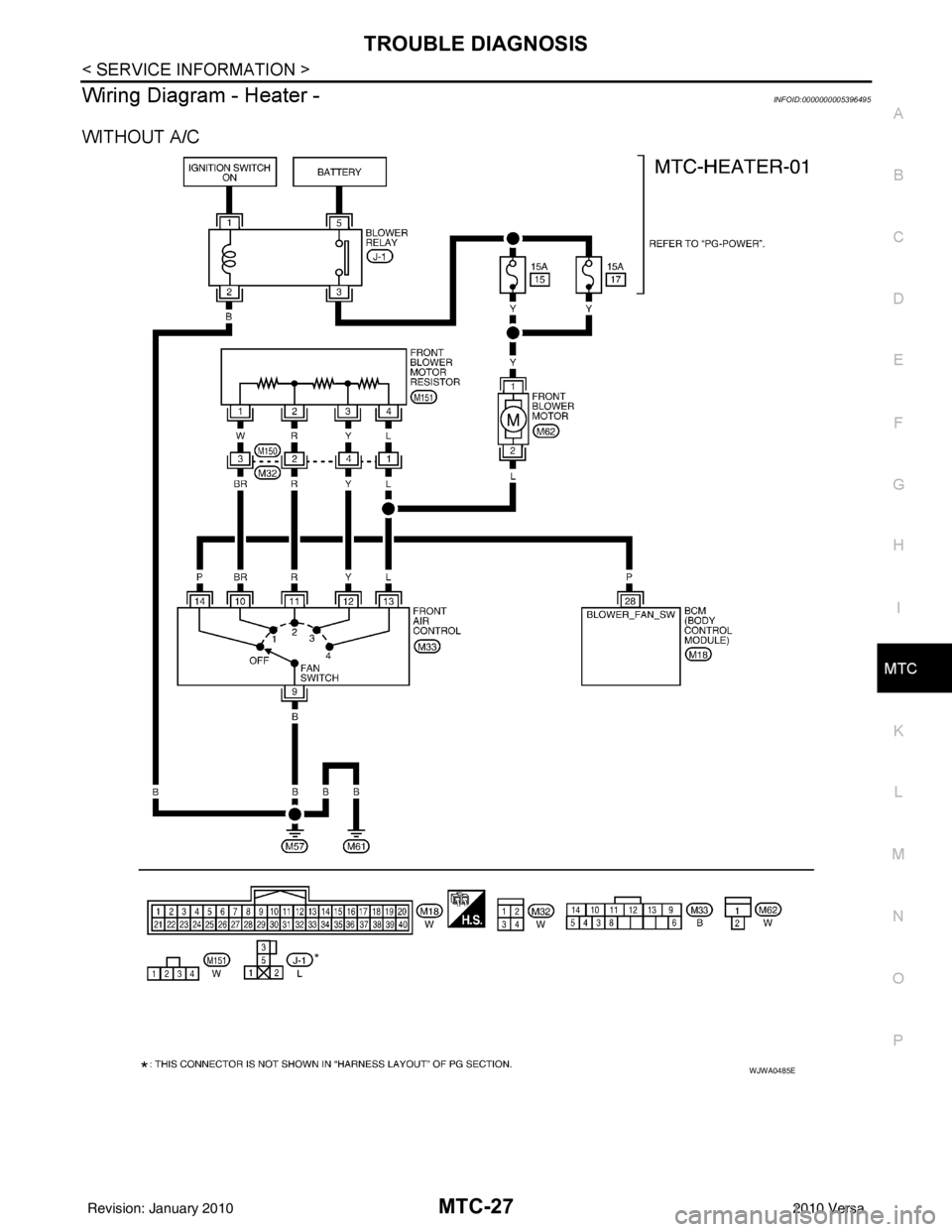
Wiring Diagram - Heater -INFOID:0000000005396495
WITHOUT A/C
WJWA0485E
Revision: January 20102010 Versa
Page 3307 of 3745

MTC-28
< SERVICE INFORMATION >
TROUBLE DIAGNOSIS
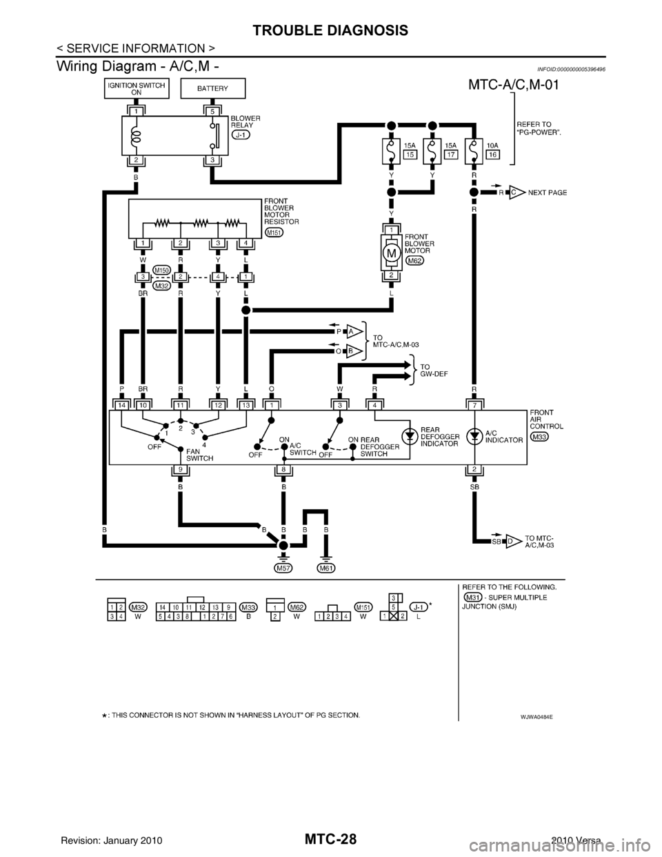
Wiring Diagram - A/C,M -
INFOID:0000000005396496
WJWA0484E
Revision: January 20102010 Versa
Page 3377 of 3745

PB-2
< SERVICE INFORMATION >
PRECAUTIONS
SERVICE INFORMATION
PRECAUTIONS
Precaution for Supplemental Restraint System (SRS) "AIR BAG" and "SEAT BELT
PRE-TENSIONER"
INFOID:0000000005397013
The Supplemental Restraint System such as “A IR BAG” and “SEAT BELT PRE-TENSIONER”, used along
with a front seat belt, helps to reduce the risk or severity of injury to the driver and front passenger for certain
types of collision. This system includes seat belt switch inputs and dual stage front air bag modules. The SRS
system uses the seat belt switches to determine the front air bag deployment, and may only deploy one front
air bag, depending on the severity of a collision and w hether the front occupants are belted or unbelted.
Information necessary to service the system safely is included in the SRS and SB section of this Service Man-
ual.
WARNING:
• To avoid rendering the SRS inopera tive, which could increase the risk of personal injury or death in
the event of a collision which would result in air bag inflation, all maintenance must be performed by
an authorized NISSAN/INFINITI dealer.
• Improper maintenance, including incorrect removal and installation of the SRS can lead to personal
injury caused by unintent ional activation of the system. For re moval of Spiral Cable and Air Bag
Module, see the SRS section.
• Do not use electrical test equipmen t on any circuit related to the SRS unless instructed to in this
Service Manual. SRS wiring harn esses can be identified by yellow and/or orange harnesses or har-
ness connectors.
PRECAUTIONS WHEN USING POWER TOOLS (AIR OR ELECTRIC) AND HAMMERS
WARNING:
• When working near the Airbag Diagnosis Sensor Unit or other Airbag System sensors with the Igni-
tion ON or engine running, DO NOT use air or electri c power tools or strike near the sensor(s) with a
hammer. Heavy vibration could activate the sensor( s) and deploy the air bag(s), possibly causing
serious injury.
• When using air or electric power tools or hammers , always switch the Ignition OFF, disconnect the
battery, and wait at least 3 minu tes before performing any service.
Precaution Necessary for Steering W heel Rotation After Battery Disconnect
INFOID:0000000005397014
NOTE:
• This Procedure is applied only to models with Intelligent Key system and NATS (NISSAN ANTI-THEFT SYS-
TEM).
• Remove and install all control units after disconnecting both battery cables with the ignition knob in the
″LOCK ″ position.
• Always use CONSULT-III to perform self-diagnosis as a part of each function inspection after finishing work.
If DTC is detected, perform trouble diagnosis according to self-diagnostic results.
For models equipped with the Intelligent Key system and NATS, an electrically controlled steering lock mech-
anism is adopted on the key cylinder.
For this reason, if the battery is disconnected or if the battery is discharged, the steering wheel will lock and
steering wheel rotation will become impossible.
If steering wheel rotation is required when battery pow er is interrupted, follow the procedure below before
starting the repair operation.
OPERATION PROCEDURE
1. Connect both battery cables. NOTE:
Supply power using jumper cables if battery is discharged.
2. Use the Intelligent Key or mechanical key to turn the ignition switch to the ″ACC ″ position. At this time, the
steering lock will be released.
3. Disconnect both battery cables. The steering lock will remain released and the steering wheel can be rotated.
4. Perform the necessary repair operation.
Revision: January 20102010 Versa
Page 3384 of 3745

PG-1
ELECTRICAL
C
DE
F
G H
I
J
L
M
SECTION PG
A
B
PG
N
O P
CONTENTS
POWER SUPPLY, GROUND & CIRCUIT ELEMENTS
SERVICE INFORMATION .. ..........................2
PRECAUTIONS .............................................. .....2
Precaution for Supplemental Restraint System
(SRS) "AIR BAG" and "SEAT BELT PRE-TEN-
SIONER" ............................................................. ......
2
Precaution Necessary for Steering Wheel Rota-
tion After Battery Disconnect ............................... ......
2
POWER SUPPLY ROUTING CIRCUIT ...............4
Schematic ........................................................... ......4
Wiring Diagram - POWER - ......................................6
Fuse ........................................................................16
Fusible Link .............................................................16
Circuit Breaker (Built Into BCM) ..............................16
Circuit Breaker ........................................................16
IPDM E/R (INTELLIGENT POWER DISTRI-
BUTION MODULE ENGINE ROOM) .................
17
System Description ............................................. ....17
CAN Communication System Description ...............18
Function of Detecting Ignition Relay Malfunction ....18
CONSULT-III Function (IPDM E/R) ..................... ....18
Auto Active Test ......................................................20
IPDM E/R Terminal Arrangement - Type A .............23
IPDM E/R Terminal Arrangement - Type B .............24
Terminal and Reference Value for IPDM E/R .........25
IPDM E/R Power/Ground Circuit Inspection ...........27
Inspection with CONSULT-III (Self-Diagnosis) .......28
Removal and Installation of IPDM E/R ................ ....28
GROUND CIRCUIT ...........................................30
Ground Distribution .............................................. ....30
HARNESS .........................................................39
Harness Layout ................................................... ....39
Wiring Diagram Codes (Cell Codes) .......................59
ELECTRICAL UNITS LOCATION ....................62
Electrical Units Location ..........................................62
HARNESS CONNECTOR .................................66
Description ...............................................................66
ELECTRICAL UNITS ........................................69
Terminal Arrangement .............................................69
STANDARDIZED RELAY .................................70
Description ...............................................................70
SUPER MULTIPLE JUNCTION (SMJ) .............72
Terminal Arrangement .............................................72
FUSE BLOCK-JUNCTION BOX (J/B) ..............74
Terminal Arrangement .............................................74
FUSE AND FUSIBLE LINK BOX ......................75
Terminal Arrangement .............................................75
Revision: January 20102010 Versa
Page 3385 of 3745

PG-2
< SERVICE INFORMATION >
PRECAUTIONS
SERVICE INFORMATION
PRECAUTIONS
Precaution for Supplemental Restraint System (SRS) "AIR BAG" and "SEAT BELT
PRE-TENSIONER"
INFOID:0000000005395347
The Supplemental Restraint System such as “A IR BAG” and “SEAT BELT PRE-TENSIONER”, used along
with a front seat belt, helps to reduce the risk or severity of injury to the driver and front passenger for certain
types of collision. This system includes seat belt switch inputs and dual stage front air bag modules. The SRS
system uses the seat belt switches to determine the front air bag deployment, and may only deploy one front
air bag, depending on the severity of a collision and w hether the front occupants are belted or unbelted.
Information necessary to service the system safely is included in the SRS and SB section of this Service Man-
ual.
WARNING:
• To avoid rendering the SRS inopera tive, which could increase the risk of personal injury or death in
the event of a collision which would result in air bag inflation, all maintenance must be performed by
an authorized NISSAN/INFINITI dealer.
• Improper maintenance, including incorrect removal and installation of the SRS can lead to personal
injury caused by unintent ional activation of the system. For re moval of Spiral Cable and Air Bag
Module, see the SRS section.
• Do not use electrical test equipmen t on any circuit related to the SRS unless instructed to in this
Service Manual. SRS wiring harn esses can be identified by yellow and/or orange harnesses or har-
ness connectors.
PRECAUTIONS WHEN USING POWER TOOLS (AIR OR ELECTRIC) AND HAMMERS
WARNING:
• When working near the Airbag Diagnosis Sensor Unit or other Airbag System sensors with the Igni-
tion ON or engine running, DO NOT use air or electri c power tools or strike near the sensor(s) with a
hammer. Heavy vibration could activate the sensor( s) and deploy the air bag(s), possibly causing
serious injury.
• When using air or electric power tools or hammers , always switch the Ignition OFF, disconnect the
battery, and wait at least 3 minu tes before performing any service.
Precaution Necessary for Steering W heel Rotation After Battery Disconnect
INFOID:0000000005995526
NOTE:
• This Procedure is applied only to models with Intelligent Key system and NATS (NISSAN ANTI-THEFT SYS-
TEM).
• Remove and install all control units after disconnecting both battery cables with the ignition knob in the
″LOCK ″ position.
• Always use CONSULT-III to perform self-diagnosis as a part of each function inspection after finishing work.
If DTC is detected, perform trouble diagnosis according to self-diagnostic results.
For models equipped with the Intelligent Key system and NATS, an electrically controlled steering lock mech-
anism is adopted on the key cylinder.
For this reason, if the battery is disconnected or if the battery is discharged, the steering wheel will lock and
steering wheel rotation will become impossible.
If steering wheel rotation is required when battery pow er is interrupted, follow the procedure below before
starting the repair operation.
OPERATION PROCEDURE
1. Connect both battery cables. NOTE:
Supply power using jumper cables if battery is discharged.
2. Use the Intelligent Key or mechanical key to turn the ignition switch to the ″ACC ″ position. At this time, the
steering lock will be released.
3. Disconnect both battery cables. The steering lock will remain released and the steering wheel can be rotated.
4. Perform the necessary repair operation.
Revision: January 20102010 Versa
Page 3389 of 3745

PG-6
< SERVICE INFORMATION >
POWER SUPPLY ROUTING CIRCUIT
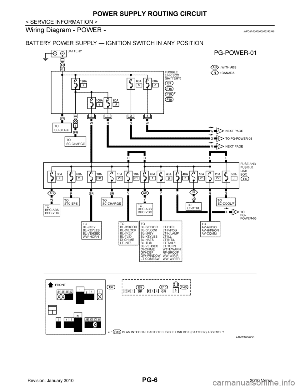
Wiring Diagram - POWER -
INFOID:0000000005395349
BATTERY POWER SUPPLY — IGNITION SWITCH IN ANY POSITION
AAMWA0248GB
Revision: January 20102010 Versa
Page 3399 of 3745

PG-16
< SERVICE INFORMATION >
POWER SUPPLY ROUTING CIRCUIT
Fuse
INFOID:0000000005395350
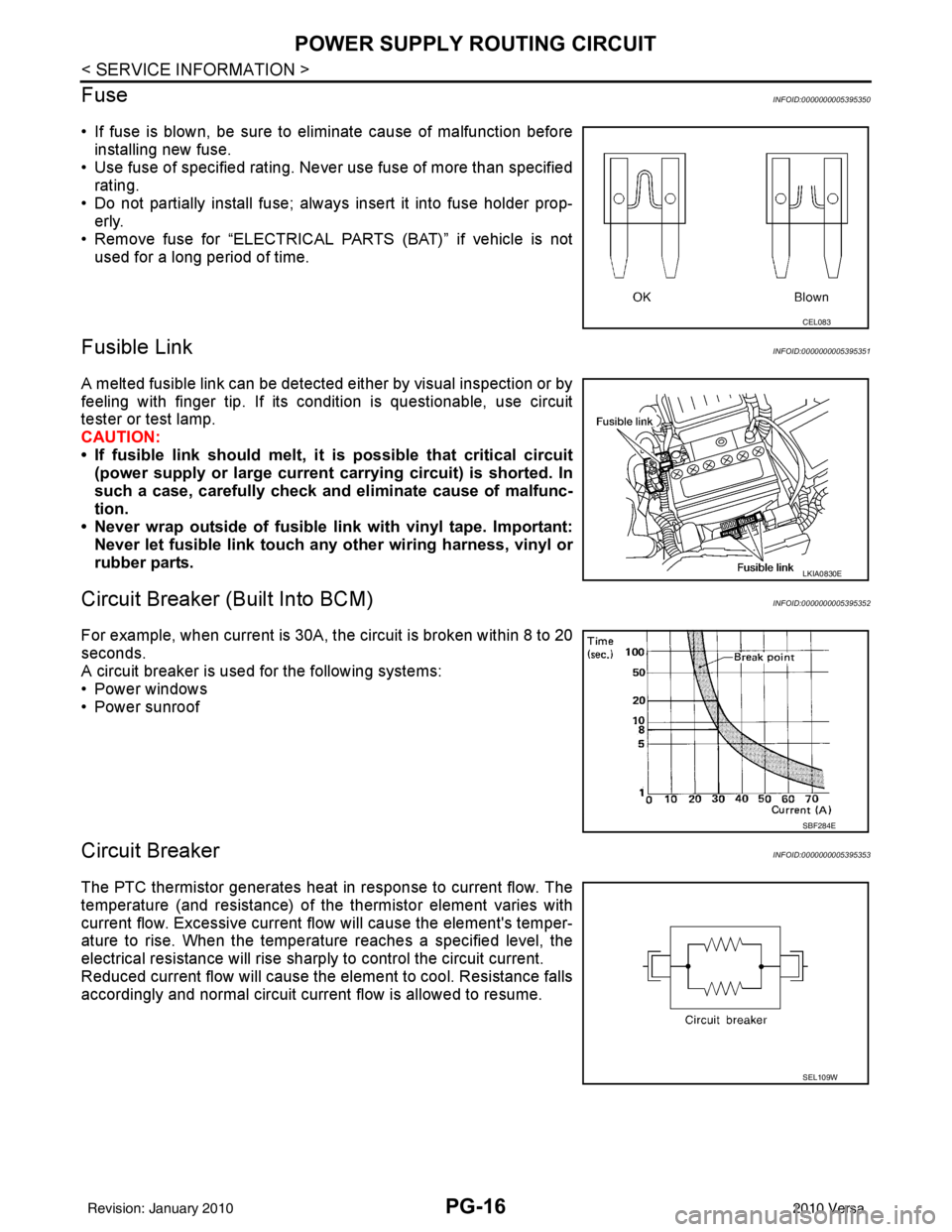
• If fuse is blown, be sure to eliminate cause of malfunction before installing new fuse.
• Use fuse of specified rating. Never use fuse of more than specified
rating.
• Do not partially install fuse; always insert it into fuse holder prop- erly.
• Remove fuse for “ELECTRICAL PARTS (BAT)” if vehicle is not used for a long period of time.
Fusible LinkINFOID:0000000005395351
A melted fusible link can be detected either by visual inspection or by
feeling with finger tip. If its condition is questionable, use circuit
tester or test lamp.
CAUTION:
• If fusible link should melt, it is possible that critical circuit
(power supply or large current carrying circuit) is shorted. In
such a case, carefully check and eliminate cause of malfunc-
tion.
• Never wrap outside of fusible link with vinyl tape. Important:
Never let fusible link touch an y other wiring harness, vinyl or
rubber parts.
Circuit Breaker (Built Into BCM)INFOID:0000000005395352
For example, when current is 30A, t he circuit is broken within 8 to 20
seconds.
A circuit breaker is used for the following systems:
• Power windows
• Power sunroof
Circuit BreakerINFOID:0000000005395353
The PTC thermistor generates heat in response to current flow. The
temperature (and resistance) of the thermistor element varies with
current flow. Excessive current flow will cause the element's temper-
ature to rise. When the temperature reaches a specified level, the
electrical resistance will rise sharply to control the circuit current.
Reduced current flow will cause the element to cool. Resistance falls
accordingly and normal circuit current flow is allowed to resume.
CEL083
LKIA0830E
SBF284E
SEL109W
Revision: January 20102010 Versa
Page 3400 of 3745

IPDM E/R (INTELLIGENT POWER DISTRIBUTION MODULE ENGINE ROOM)
PG-17
< SERVICE INFORMATION >
C
D E
F
G H
I
J
L
M A
B
PG
N
O P
IPDM E/R (INTELLIGENT POWER DISTRIBUTION MODULE ENGINE
ROOM)
System DescriptionINFOID:0000000005395354
• IPDM E/R (Intelligent Power Distribution Module Engi ne Room) integrates the relay box and fuse block
which were originally placed in engine compartment. It controls integrated relays via IPDM E/R control cir-
cuits.
• IPDM E/R-integrated control circuits perform ON-OFF operation of relays, CAN communication control, oil pressure switch signal reception, etc.
• It controls operation of each electrical co mponent via ECM, BCM and CAN communication lines.
CAUTION:
None of the IPDM E/R integr ated relays can be removed.
SYSTEMS CONTROLLED BY IPDM E/R
1. Lamp control
Using CAN communication lines, it receives signals from the BCM and controls the following lamps:
• Headlamps (High, Low)
• Parking lamps
• Tail and license plate lamps
• Front fog lamps
2. Wiper control Using CAN communication lines, it receives signals from the BCM and controls the front wipers.
3. Rear window defogger relay control Using CAN communication lines, it receives signals from the BCM and controls the rear window defogger
relay.
4. A/C compressor control Using CAN communication lines, it receives signal s from the ECM and controls the A/C compressor
(magnet clutch).
5. Starter control Using CAN communication lines, it receives signals from the BCM and controls the starter relay.
6. Cooling fan control Using CAN communication lines, it receives signals from the ECM and controls the cooling fan relays.
7. Horn control Using CAN communication lines, it receives signals from the BCM and controls the horn relay.
8. Daytime light system control (Canada only) Using CAN communication lines, it receives signals from the BCM and controls the daytime light relay.
CAN COMMUNICATION LINE CONTROL
With CAN communication, by connecting each control unit using two communication lines (CAN L-line, CAN
H-line), it is possible to transmit a maximum amount of information with minimum wiring. Each control unit can
transmit and receive data, and reads necessary information only.
1. Fail-safe control • When CAN communication with other control units is impossible, IPDM E/R performs fail-safe control.
After CAN communication returns to normal operation, it also returns to normal control.
• Operation of control parts by IPDM E/ R during fail-safe mode is as follows:
Controlled system Fail-safe mode
Headlamp • With the ignition switch ON, headlamp low relay is ON, headlamp high relays are OFF, and
daytime light system (Canada only) is OFF.
• With the ignition switch OFF, the headlamp relays are OFF.
Tail, license plate and parking lamps • With the ignition switch ON, the tail lamp relay is ON. • With the ignition switch OFF, the tail lamp relay is OFF.
Cooling fan • With the ignition switch ON, cooling fan relay-1, relay-2, and relay-3 are ON.
• With the ignition switch OFF, all cooling fan relays are OFF.
Front wiper Until the ignition switch is turned off, the front wiper relays remain in the same status they
were in just before fail
−safe control was initiated.
Revision: January 20102010 Versa