2010 NISSAN TIIDA service indicator
[x] Cancel search: service indicatorPage 69 of 3745
AT-52
< SERVICE INFORMATION >
TROUBLE DIAGNOSIS
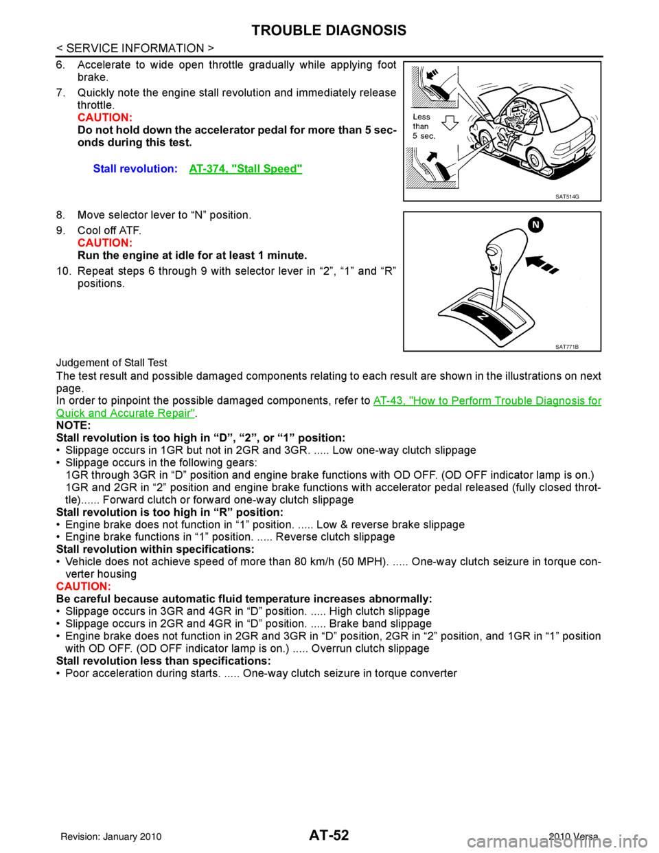
6. Accelerate to wide open throttle gradually while applying footbrake.
7. Quickly note the engine stall revolution and immediately release throttle.
CAUTION:
Do not hold down the accelerator pedal for more than 5 sec-
onds during this test.
8. Move selector lever to “N” position.
9. Cool off ATF. CAUTION:
Run the engine at idle for at least 1 minute.
10. Repeat steps 6 through 9 with selector lever in “2”, “1” and “R” positions.
Judgement of Stall Test
The test result and possible damaged components relating to each result are shown in the illustrations on next
page.
In order to pinpoint the possible damaged components, refer to AT-43, "
How to Perform Trouble Diagnosis for
Quick and Accurate Repair".
NOTE:
Stall revolution is too high in “D”, “2”, or “1” position:
• Slippage occurs in 1GR but not in 2GR and 3GR. ..... Low one-way clutch slippage
• Slippage occurs in the following gears:
1GR through 3GR in “D” position and engine brake functions with OD OFF. (OD OFF indicator lamp is on.)
1GR and 2GR in “2” position and engine brake functions with accelerator pedal released (fully closed throt-
tle)...... Forward clutch or forward one-way clutch slippage
Stall revolution is too high in “R” position:
• Engine brake does not function in “1” posit ion. ..... Low & reverse brake slippage
• Engine brake functions in “1” position. ..... Reverse clutch slippage
Stall revolution within specifications:
• Vehicle does not achieve speed of more than 80 km/h ( 50 MPH). ..... One-way clutch seizure in torque con-
verter housing
CAUTION:
Be careful because automatic flui d temperature increases abnormally:
• Slippage occurs in 3GR and 4GR in “D” position. ..... High clutch slippage
• Slippage occurs in 2GR and 4GR in “D” position. ..... Brake band slippage
• Engine brake does not function in 2GR and 3GR in “D” pos ition, 2GR in “2” position, and 1GR in “1” position
with OD OFF. (OD OFF indicator lamp is on.) ..... Overrun clutch slippage
Stall revolution less than specifications:
• Poor acceleration during starts. ..... One-way clutch seizure in torque converter Stall revolution:
AT-374, "
Stall Speed"
SAT514G
SAT771B
Revision: January 20102010 Versa
Page 73 of 3745
AT-56
< SERVICE INFORMATION >
TROUBLE DIAGNOSIS
• Before road test, familiarize yourself with all test procedures anditems to check.
• Test all inspection items until the symptom is uncovered. Include
NG items in “Diagnostic Wo rksheet Chart”(Refer to AT- 4 3
). Per-
form a diagnosis of the NG items after the completion of all the
road tests.
Check Before Engine Is StartedINFOID:0000000005397242
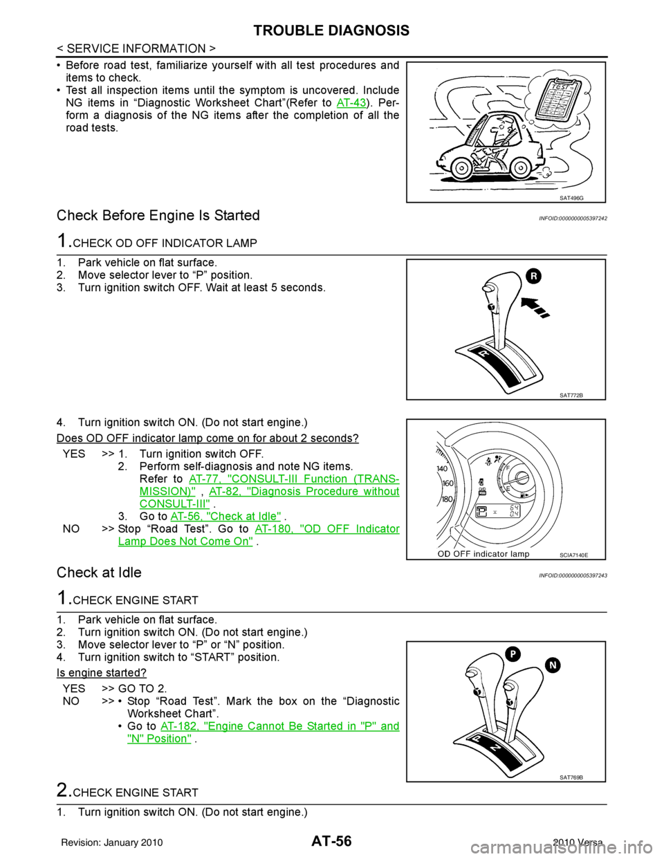
1.CHECK OD OFF INDICATOR LAMP
1. Park vehicle on flat surface.
2. Move selector lever to “P” position.
3. Turn ignition switch OFF. Wait at least 5 seconds.
4. Turn ignition switch ON. (Do not start engine.)
Does OD OFF indicator lamp come on for about 2 seconds?
YES >> 1. Turn ignition switch OFF. 2. Perform self-diagnosis and note NG items.Refer to AT-77, "
CONSULT-III Function (TRANS-
MISSION)" , AT-82, "Diagnosis Procedure without
CONSULT-III" .
3. Go to AT-56, "
Check at Idle" .
NO >> Stop “Road Test”. Go to AT-180, "
OD OFF Indicator
Lamp Does Not Come On" .
Check at IdleINFOID:0000000005397243
1.CHECK ENGINE START
1. Park vehicle on flat surface.
2. Turn ignition switch ON. (Do not start engine.)
3. Move selector lever to “P” or “N” position.
4. Turn ignition switch to “START” position.
Is engine started?
YES >> GO TO 2.
NO >> • Stop “Road Test”. Mark the box on the “Diagnostic Worksheet Chart”.
•Go to AT-182, "
Engine Cannot Be Started in "P" and
"N" Position" .
2.CHECK ENGINE START
1. Turn ignition switch ON. (Do not start engine.)
SAT496G
SAT772B
SCIA7140E
SAT769B
Revision: January 20102010 Versa
Page 76 of 3745
TROUBLE DIAGNOSISAT-59
< SERVICE INFORMATION >
DE
F
G H
I
J
K L
M A
B
AT
N
O P
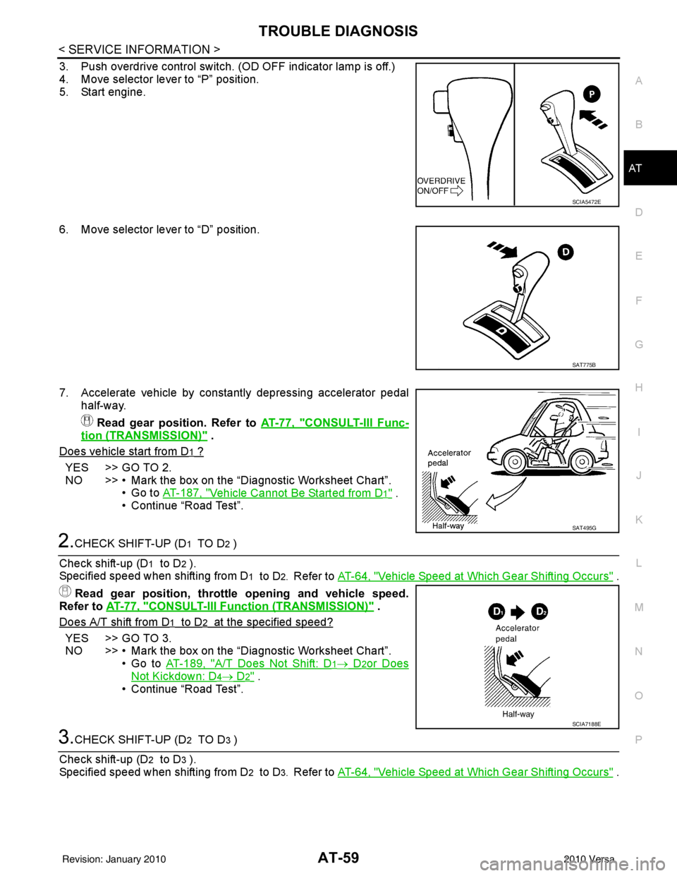
3. Push overdrive control switch. (OD OFF indicator lamp is off.)
4. Move selector lever to “P” position.
5. Start engine.
6. Move selector lever to “D” position.
7. Accelerate vehicle by constantly depressing accelerator pedal half-way.
Read gear position. Refer to AT-77, "
CONSULT-III Func-
tion (TRANSMISSION)" .
Does vehicle start from D
1 ?
YES >> GO TO 2.
NO >> • Mark the box on the “D iagnostic Worksheet Chart”.
•Go to AT-187, "
Vehicle Cannot Be Started from D1" .
• Continue “Road Test”.
2.CHECK SHIFT-UP (D1 TO D2 )
Check shift-up (D
1 to D2 ).
Specified speed when shifting from D
1 to D2. Refer to AT-64, "Vehicle Speed at Which Gear Shifting Occurs" .
Read gear position, throttle opening and vehicle speed.
Refer to AT-77, "
CONSULT-III Function (TRANSMISSION)" .
Does A/T shift from D
1 to D2 at the specified speed?
YES >> GO TO 3.
NO >> • Mark the box on the “D iagnostic Worksheet Chart”.
•Go to AT-189, "
A/T Does Not Shift: D1→ D2or Does
Not Kickdown: D4→ D2" .
• Continue “Road Test”.
3.CHECK SHIFT-UP (D2 TO D3 )
Check shift-up (D
2 to D3 ).
Specified speed when shifting from D
2 to D3. Refer to AT-64, "Vehicle Speed at Which Gear Shifting Occurs" .
SCIA5472E
SAT775B
SAT495G
SCIA7188E
Revision: January 20102010 Versa
Page 78 of 3745
TROUBLE DIAGNOSISAT-61
< SERVICE INFORMATION >
DE
F
G H
I
J
K L
M A
B
AT
N
O P
• Continue “Road Test”.
8.CHECK SHIFT-DOWN (D4 TO D3 )
Decelerate vehicle by applying foot brake lightly. Read gear position and engine speed. Refer to AT-77, "
CON-
SULT-III Function (TRANSMISSION)" .
Does engine speed return to idle smoothly when A/T is shifted from
D4 to D3 ?
YES >> 1. Stop vehicle. 2. Go to AT-61, "
Cruise Test - Part 2" .
NO >> • Mark the box on the “D iagnostic Worksheet Chart”.
•Go to AT-196, "
Engine Speed Does Not Return to Idle
(Light Braking D4→ D3)" .
• Continue “Road Test”.
Cruise Test - Part 2INFOID:0000000005397245
1.CHECK STARTING GEAR (D1 ) POSITION
1. Push overdrive control switch. (OD OFF indicator lamp is off.)
2. Move selector lever to “D” position.
3. Accelerate vehicle by half throttle again. Read gear position. Refer to AT-77, "
CONSULT-III Func-
tion (TRANSMISSION)" .
Does vehicle start from D
1 ?
YES >> GO TO 2.
NO >> • Mark the box on the “D iagnostic Worksheet Chart”.
•Go to AT-187, "
Vehicle Cannot Be Started from D1" .
• Continue “Road Test”.
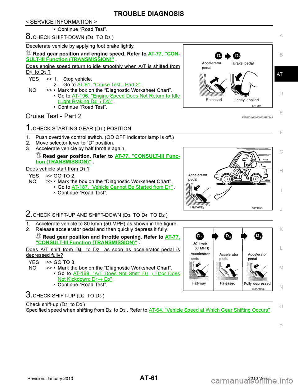
2.CHECK SHIFT-UP AND SHIFT-DOWN (D3 TO D4 TO D2 )
1. Accelerate vehicle to 80 km/h (50 MPH) as shown in the figure.
2. Release accelerator pedal and then quickly depress it fully. Read gear position and th rottle opening. Refer to AT-77,
"CONSULT-III Function (TRANSMISSION)" .
Does A/T shift from D
4 to D2 as soon as accelerator pedal is
depressed fully?
YES >> GO TO 3.
NO >> • Mark the box on the “D iagnostic Worksheet Chart”.
•Go to AT-189, "
A/T Does Not Shift: D1→ D2or Does
Not Kickdown: D4→ D2" .
• Continue “Road Test”.
3.CHECK SHIFT-UP (D2 TO D3 )
Check shift-up (D
2 to D3 )
Specified speed when shifting from D
2 to D3 . Refer to AT-64, "Vehicle Speed at Which Gear Shifting Occurs" .
SAT959I
SAT495G
SCIA7192E
Revision: January 20102010 Versa
Page 79 of 3745
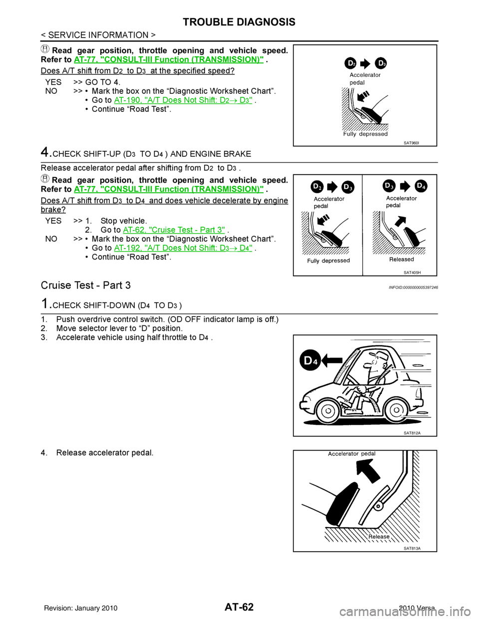
AT-62
< SERVICE INFORMATION >
TROUBLE DIAGNOSIS
Read gear position, throttle opening and vehicle speed.
Refer to AT-77, "
CONSULT-III Function (TRANSMISSION)" .
Does A/T shift from D
2 to D3 at the specified speed?
YES >> GO TO 4.
NO >> • Mark the box on the “Diagnostic Worksheet Chart”. •Go to AT-190, "
A/T Does Not Shift: D2→ D3" .
• Continue “Road Test”.
4.CHECK SHIFT-UP (D3 TO D4 ) AND ENGINE BRAKE
Release accelerator pedal after shifting from D
2 to D3 .
Read gear position, throttle opening and vehicle speed.
Refer to AT-77, "
CONSULT-III Function (TRANSMISSION)" .
Does A/T shift from D
3 to D4 and does vehicle decelerate by engine
brake?
YES >> 1. Stop vehicle. 2. Go to AT-62, "
Cruise Test - Part 3" .
NO >> • Mark the box on the “Diagnostic Worksheet Chart”.
•Go to AT-192, "
A/T Does Not Shift: D3→ D4" .
• Continue “Road Test”.
Cruise Test - Part 3INFOID:0000000005397246
1.CHECK SHIFT-DOWN (D4 TO D3 )
1. Push overdrive control switch. (OD OFF indicator lamp is off.)
2. Move selector lever to “D” position.
3. Accelerate vehicle using half throttle to D
4 .
4. Release accelerator pedal.
SAT960I
SAT405H
SAT812A
SAT813A
Revision: January 20102010 Versa
Page 80 of 3745
TROUBLE DIAGNOSISAT-63
< SERVICE INFORMATION >
DE
F
G H
I
J
K L
M A
B
AT
N
O P
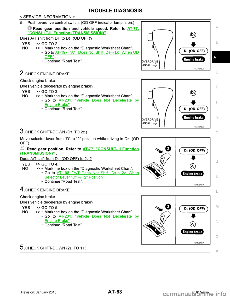
5. Push overdrive control switch. (OD OFF indicator lamp is on.) Read gear position and vehicle speed. Refer to AT-77,
"CONSULT-III Function (TRANSMISSION)" .
Does A/T shift from D
4 to D3 (OD OFF)?
YES >> GO TO 2.
NO >> • Mark the box on the “D iagnostic Worksheet Chart”.
•Go to AT-197, "
A/T Does Not Shift: D4→ D3, When OD
OFF" .
• Continue “Road Test”.
2.CHECK ENGINE BRAKE
Check engine brake.
Does vehicle decelerate by engine brake?
YES >> GO TO 3.
NO >> • Mark the box on the “D iagnostic Worksheet Chart”.
•Go to AT-201, "
Vehicle Does Not Decelerate by
Engine Brake" .
• Continue “Road Test”.
3.CHECK SHIFT-DOWN (D3 TO 22 )
Move selector lever from “D” to “2” position while driving in D
3 (OD
OFF).
Read gear position. Refer to AT-77, "
CONSULT-III Function
(TRANSMISSION)" .
Does A/T shift from D
3 (OD OFF) to 22 ?
YES >> GO TO 4.
NO >> • Mark the box on the “D iagnostic Worksheet Chart”.
•Go to AT-198, "
A/T Does Not Shift: D3→ 22, When
Selector Lever "D" → "2" Position" .
• Continue “Road Test”.
4.CHECK ENGINE BRAKE
Check engine brake.
Does vehicle decelerate by engine brake?
YES >> GO TO 5.
NO >> • Mark the box on the “D iagnostic Worksheet Chart”.
•Go to AT-201, "
Vehicle Does Not Decelerate by
Engine Brake" .
• Continue “Road Test”.
5.CHECK SHIFT-DOWN (22 TO 11 )
SCIA5469E
SCIA5469E
SAT791GA
SAT791GA
Revision: January 20102010 Versa
Page 96 of 3745

TROUBLE DIAGNOSISAT-79
< SERVICE INFORMATION >
DE
F
G H
I
J
K L
M A
B
AT
N
O P
SELF-DIAGNOSTIC RESULT MODE
Display Items List
OVERRUN/C S/V When overrun clutch solenoid valve operates.
(When overrun clutch disengaged. Refer to
AT-22 .) ON
When overrun clutch solenoid valve does not
operate. (When overrun clutch engaged. Refer
to AT- 2 2
.) OFF
BRAKE SW Depressed brake pedal.
ON
Released brake pedal. OFF
GEAR During driving 1, 2, 3, 4
SLCT LVR POSI When setting selector lever to “N” or “P” posi-
tions.
N · P
When setting selector lever to “R” position. R
When setting selector lever to “D” position. D
When setting selector lever to “2” position. 2
When setting selector lever to “1” position. 1
VEHICLE SPEED During driving Approximately matches the speedometer
reading.
LINE PRES DTY Line pressure low ⇔ Line pressure high 0 % ⇔ 94 %
TCC S/V DUTY Lock-up OFF ⇔ Lock-up ON 4 % ⇔ 94 %
Item name
Condition Display value (Approx.)
Items (CONSULT-III
screen terms) Malfunction is detected when... OBD-II (DTC)
Reference page
MIL indicator
lamp*1, “EN-
GINE” with
CONSULT-III
or GST
CAN COMM CIRCUIT • When TCM is not transmitting or receiving CAN communication signal
for 2 seconds or more. U1000
AT- 8 7
T/M RANGE SENSOR A • TCM does not receive the correct voltage signal (based on the gear
position) from the switch. P0705
AT- 9 0
FLUID TEMP SENSOR
A • TCM receives an excessively low or high voltage from the sensor. P0710
AT- 9 5
OUTPUT SPEED SEN-
SOR• TCM does not receive the proper voltage signal from the sensor.
P0720AT- 1 0 0
ENGINE SPEED • TCM does not re ceive the proper voltage signal from the ECM. P0725AT- 1 0 5
1GR INCORRECT RA-
TIO • A/T cannot be shifted to the 1GR position even if electrical circuit is
good. P0731*2AT- 1 0 9
2GR INCORRECT RA-
TIO• A/T cannot be shifted to the 2GR position even if electrical circuit is
good. P0732*2AT- 11 2
3GR INCORRECT RA-
TIO• A/T cannot be shifted to the 3GR position even if electrical circuit is
good. P0733*2AT- 11 5
4GR INCORRECT RA-
TIO• A/T cannot be shifted to the 4GR position even if electrical circuit is
good. P0734*2AT- 11 8
TORQUE CONVERTER• TCM detects an improper voltage drop when it tries to operate the so-
lenoid valve. P0740
AT- 1 2 3
TORQUE CONVERTER • A/T cannot perform lock-up even if electrical circuit is good.
P0744*2AT- 1 2 8
PC SOLENOID A• TCM detects an improper voltage drop when it tries to operate the so-
lenoid valve. P0745
AT- 1 3 3
Revision: January 20102010 Versa
Page 97 of 3745
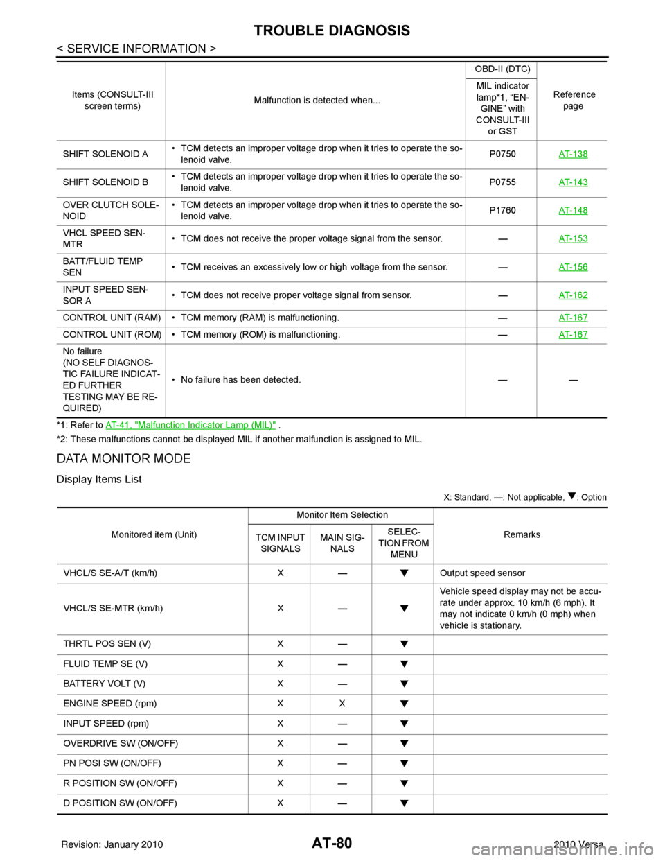
AT-80
< SERVICE INFORMATION >
TROUBLE DIAGNOSIS
*1: Refer to AT- 4 1 , "Malfunction Indicator Lamp (MIL)" .
*2: These malfunctions cannot be displayed MIL if another malfunction is assigned to MIL.
DATA MONITOR MODE
Display Items List
X: Standard, —: Not applicable, : Option
SHIFT SOLENOID A • TCM detects an improper voltage drop when it tries to operate the so-
lenoid valve. P0750
AT- 1 3 8
SHIFT SOLENOID B • TCM detects an improper voltage drop when it tries to operate the so-
lenoid valve. P0755
AT- 1 4 3
OVER CLUTCH SOLE-
NOID • TCM detects an improper voltage drop when it tries to operate the so-
lenoid valve. P1760
AT- 1 4 8
VHCL SPEED SEN-
MTR • TCM does not receive the proper voltage signal from the sensor.
—AT- 1 5 3
BATT/FLUID TEMP
SEN • TCM receives an excessively low or high voltage from the sensor.
—AT- 1 5 6
INPUT SPEED SEN-
SOR A • TCM does not receive proper voltage signal from sensor.
—AT- 1 6 2
CONTROL UNIT (RAM) • TCM memory (RAM) is malfunctioning. —AT- 1 6 7
CONTROL UNIT (ROM) • TCM memory (ROM) is malfunctioning. —AT- 1 6 7
No failure
(NO SELF DIAGNOS-
TIC FAILURE INDICAT-
ED FURTHER
TESTING MAY BE RE-
QUIRED) • No failure has been detected.
——
Items (CONSULT-III
screen terms) Malfunction is detected when... OBD-II (DTC)
Reference page
MIL indicator
lamp*1, “EN-
GINE” with
CONSULT-III or GST
Monitored item (Unit) Monitor Item Selection
Remarks
TCM INPUT
SIGNALS MAIN SIG-
NALS SELEC-
TION FROM MENU
VHCL/S SE-A/T (km/h) X— Output speed sensor
VHCL/S SE-MTR (km/h) X— Vehicle speed display may not be accu-
rate under approx. 10 km/h (6 mph). It
may not indicate 0 km/h (0 mph) when
vehicle is stationary.
THRTL POS SEN (V) X—
FLUID TEMP SE (V) X—
BATTERY VOLT (V) X—
ENGINE SPEED (rpm) XX
INPUT SPEED (rpm) X—
OVERDRIVE SW (ON/OFF) X—
PN POSI SW (ON/OFF) X—
R POSITION SW (ON/OFF) X—
D POSITION SW (ON/OFF) X—
Revision: January 20102010 Versa