2010 NISSAN TIIDA service indicator
[x] Cancel search: service indicatorPage 47 of 3745
AT-30
< SERVICE INFORMATION >
A/T CONTROL SYSTEM
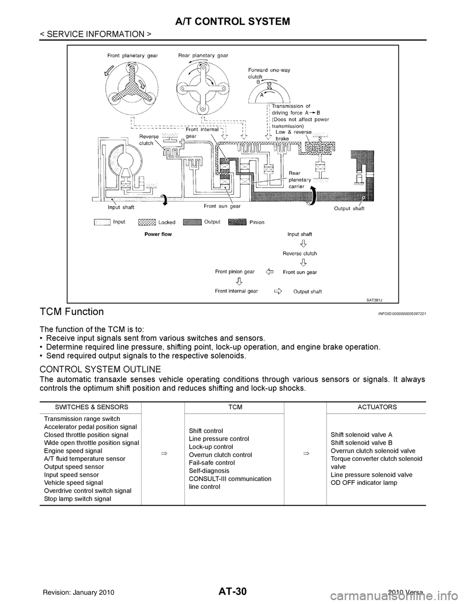
TCM Function
INFOID:0000000005397221
The function of the TCM is to:
• Receive input signals sent from various switches and sensors.
• Determine required line pressure, shifting poi nt, lock-up operation, and engine brake operation.
• Send required output signals to the respective solenoids.
CONTROL SYSTEM OUTLINE
The automatic transaxle senses vehicle operating conditions through various sensors or signals. It always
controls the optimum shift position and reduces shifting and lock-up shocks.
SAT381J
SWITCHES & SENSORS
⇒TCM
⇒ACTUATORS
Transmission range switch
Accelerator pedal position signal
Closed throttle position signal
Wide open throttle position signal
Engine speed signal
A/T fluid temperature sensor
Output speed sensor
Input speed sensor
Vehicle speed signal
Overdrive control switch signal
Stop lamp switch signal Shift control
Line pressure control
Lock-up control
Overrun clutch control
Fail-safe control
Self-diagnosis
CONSULT-III communication
line control
Shift solenoid valve A
Shift solenoid valve B
Overrun clutch solenoid valve
Torque converter clutch solenoid
valve
Line pressure solenoid valve
OD OFF indicator lamp
Revision: January 20102010 Versa
Page 49 of 3745
AT-32
< SERVICE INFORMATION >
A/T CONTROL SYSTEM
*1: Output speed sensor
*2: Spare for accelerator pedal position signal
*3: If these input and output signals are different, the TCM triggers the fail-safe function.
*4: Used as a condition for starting self-diagnostics; if self-diagnosis are not started, it is judged that there is some kind of error.
*5: Input by CAN communications.
*6: Output by CAN communications.
Line Pressure ControlINFOID:0000000005397224
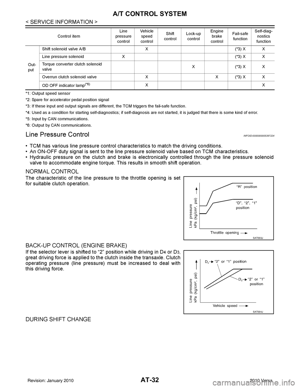
• TCM has various line pressure control char acteristics to match the driving conditions.
• An ON-OFF duty signal is sent to the line pres sure solenoid valve based on TCM characteristics.
• Hydraulic pressure on the clutch and brake is electronically controlled through the line pressure solenoid valve to accommodate engine torque. This results in smooth shift operation.
NORMAL CONTROL
The characteristic of the line pressure to the throttle opening is set
for suitable clutch operation.
BACK-UP CONTROL (ENGINE BRAKE)
If the selector lever is shifted to “2” position while driving in D4 or D3,
great driving force is applied to the clutch inside the transaxle. Clutch
operating pressure (line pressure) must be increased to deal with
this driving force.
DURING SHIFT CHANGE
Out-
put Shift solenoid valve A/B
X(*3) X X
Line pressure solenoid X (*3) X X
Torque converter clutch solenoid
valve X(
*3 ) X X
Overrun clutch solenoid valve XX (*3) X X
OD OFF indicator lamp
(*6)XX
Control item
Line
pressure
control Vehicle
speed
control Shift
control Lock-up
control Engine
brake
control Fail-safe
function Self-diag-
nostics
function
SAT003J
SAT004J
Revision: January 20102010 Versa
Page 56 of 3745
ON BOARD DIAGNOSTIC (OBD) SYSTEMAT-39
< SERVICE INFORMATION >
DE
F
G H
I
J
K L
M A
B
AT
N
O P
ON BOARD DIAGNOSTIC (OBD) SYSTEM
IntroductionINFOID:0000000005397230
A/T system has two self-diagnostic systems.
The first is emission-related on board diagnostic system (OBD-II) performed by the TCM in combination with
the ECM. The malfunction is indicated by the MIL (malf unction indicator lamp) and is stored as a DTC in the
ECM memory but not the TCM memory.
The second is the TCM original self-diagnosis indicated by the OD OFF indicator lamp. The malfunction is
stored in the TCM memory. The detected items are ov erlapped with OBD-II self-diagnostic items. For detail,
refer to AT-77, "
CONSULT-III Function (TRANSMISSION)" .
OBD-II Function for A/T SystemINFOID:0000000005397231
The ECM provides emission-related on board diagnostic (O BD-II) functions for the A/T system. One function
is to receive a signal from the TCM used with OBD-rela ted parts of the A/T system. The signal is sent to the
ECM when a malfunction occurs in the corresponding OBD-re lated part. The other function is to indicate a
diagnostic result by means of the MIL (malfunction indica tor lamp) on the instrument panel. Sensors, switches
and solenoid valves are used as sensing elements.
The MIL automatically illuminates in One or Two Trip Detection Logic when a malfunction is sensed in relation
to A/T system parts.
One or Two Trip Detection Logic of OBD-IIINFOID:0000000005397232
ONE TRIP DETECTION LOGIC
If a malfunction is sensed during the first test drive, the MIL will illuminate and the malfunction will be stored in
the ECM memory as a DTC. The TCM is not provided with such a memory function.
TWO TRIP DETECTION LOGIC
When a malfunction is sensed during the first test drive, it is stored in the ECM memory as a 1st trip DTC
(diagnostic trouble code) or 1st trip freeze frame data. At this point, the MIL will not illuminate. — 1st trip
If the same malfunction as that experienced during the fi rst test drive is sensed during the second test drive,
the MIL will illuminate. — 2nd trip
The “trip” in the “One or Two Trip Detection Logic” m eans a driving mode in which self-diagnosis is performed
during vehicle operation.
OBD-II Diagnostic Trouble Code (DTC)INFOID:0000000005397233
HOW TO READ DTC AND 1ST TRIP DTC
DTC and 1st trip DTC can be read by the following methods.
( with CONSULT-III or GST) CONSULT-III or GST (Generic Scan Tool) Examples: P0705, P0720 etc.
These DTC are prescribed by SAE J2012.
(CONSULT-III also displays the malfunctioning component or system.)
• 1st trip DTC No. is the same as DTC No.
• Output of the diagnostic trouble code indicates that the indicated circuit has a malfunction. How-
ever, in case of the Mode II and GST, they do not indicate whether the malfunction is still occurring or
occurred in the past and returned to normal.
CONSULT-III can identify them as shown below, therefore, CONS ULT-III (if available) is recom-
mended.
DTC or 1st trip DTC of a malfunction is displayed in SELF-DIAGNOSTIC RESULTS mode for “ENGINE” with
CONSULT-III. Time data indicates how many times the vehicle was driven after the last detection of a DTC.
If the DTC is being detected curr ently, the time data will be “0”.
If a 1st trip DTC is stored in the ECM, the time data will be “1t”.
Freeze Frame Data and 1st Trip Freeze Frame Data
The ECM has a memory function, which stores the driv ing condition such as fuel system status, calculated
load value, engine coolant temperature, short term f uel trim, long term fuel trim, engine speed and vehicle
speed at the moment the ECM detects a malfunction.
Revision: January 20102010 Versa
Page 58 of 3745
ON BOARD DIAGNOSTIC (OBD) SYSTEMAT-41
< SERVICE INFORMATION >
DE
F
G H
I
J
K L
M A
B
AT
N
O P
The OD OFF indicator lamp is located on the combination meter.
1. If the ignition switch stays ON after repair work, be su re to turn ignition switch OFF once. Wait at least 10
seconds and then turn it ON (engine stopped) again.
2. Perform “TCM SELF-DIAGNOSTIC PR OCEDURE (No Tools)”. Refer to AT-82, "
Diagnosis Procedure
without CONSULT-III". (The engine warm-up step can be skipped when performing the diagnosis only to
erase the DTC.)
3. Perform “OBD-II SELF-DIAGNOSTIC PROCEDURE (No tools)”. Refer to EC-84, "
Diagnosis Description"
(HR16DE), EC-542, "Emission-related Diagnostic Information" (MR18DE).
Malfunction Indicator Lamp (MIL)INFOID:0000000005397234
DESCRIPTION
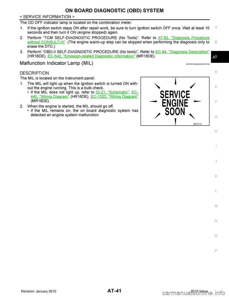
The MIL is located on the instrument panel.
1. The MIL will light up when the ignition switch is turned ON with-
out the engine running. This is a bulb check.
• If the MIL does not light up, refer to DI-21, "
Schematic", EC-
440, "Wiring Diagram" (HR16DE), EC-1033, "Wiring Diagram"
(MR18DE).
2. When the engine is start ed, the MIL should go off.
• If the MIL remains on, the on board diagnostic system has detected an engine system malfunction.
SEF217U
Revision: January 20102010 Versa
Page 63 of 3745

AT-46
< SERVICE INFORMATION >
TROUBLE DIAGNOSIS
Diagnostic Worksheet Chart
Customer name MR./MS Model & YearVIN
Trans. model EngineMileage
Incident Date Manuf. DateIn Service Date
Frequency † Continuous † Intermittent ( times a day)
Symptoms † Vehicle does not move. ( † Any position † Particular position)
† No up-shift ( † 1st → 2nd † 2nd → 3rd † 3rd → 4th)
† No down-shift ( † 4th → 3rd † 3rd → 2nd† 2nd → 1st)
† Lock-up malfunction
† Shift point too high or too low.
† Shift shock or slip ( † N → D † Lock-up † Any drive position)
† Noise or vibration
† No kick down
† No pattern select
† Others
()
Malfunction indicator lamp (MIL) † Continuously lit † Not lit
1. † Read the Fail-safe and listen to customer complaints. AT- 4 2,
"Information
from
customer"
2. † Check A/T fluid AT- 1 7
† Leakage (Follow specified procedure)
† Fluid condition
† Fluid level
3. † Perform “STALL TEST” and “LINE PRESSURE TEST”. AT- 5 1
†“STALL TEST”— Mark possible damaged components/others.
† Torque converter one-way clutch
† Reverse clutch
† Forward clutch
† Overrun clutch
† Forward one-way clutch †
Low & reverse brake
† Low one-way clutch
† Engine
† Line pressure is low
† Clutches and brakes except high clutch and
brake band are OK
† “LINE PRESSURE TEST”— Suspected parts:
Revision: January 20102010 Versa
Page 64 of 3745
TROUBLE DIAGNOSISAT-47
< SERVICE INFORMATION >
DE
F
G H
I
J
K L
M A
B
AT
N
O P
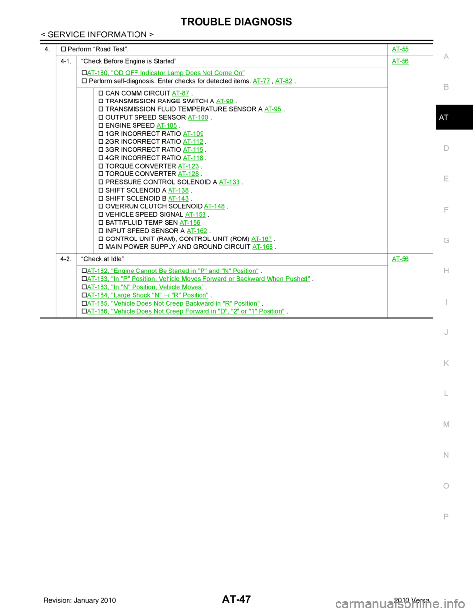
4. † Perform “Road Test”. AT- 5 5
4-1. “Check Before Engine is Started” AT- 5 6
†AT- 1 8 0 , "OD OFF Indicator Lamp Does Not Come On"
† Perform self-diagnosis. Enter checks for detected items. AT- 7 7 , AT- 8 2 .
† CAN COMM CIRCUIT AT- 8 7
.
† TRANSMISSION RANGE SWITCH A AT- 9 0
.
† TRANSMISSION FLUID TEMPERATURE SENSOR A AT- 9 5
.
† OUTPUT SPEED SENSOR AT- 1 0 0
.
† ENGINE SPEED AT- 1 0 5
.
† 1GR INCORRECT RATIO AT- 1 0 9
† 2GR INCORRECT RATIO AT- 11 2 .
† 3GR INCORRECT RATIO AT- 11 5
.
† 4GR INCORRECT RATIO AT- 11 8
.
† TORQUE CONVERTER AT- 1 2 3
.
† TORQUE CONVERTER AT- 1 2 8
.
† PRESSURE CONTROL SOLENOID A AT- 1 3 3
.
† SHIFT SOLENOID A AT- 1 3 8
.
† SHIFT SOLENOID B AT- 1 4 3
.
† OVERRUN CLUTCH SOLENOID AT- 1 4 8
.
† VEHICLE SPEED SIGNAL AT- 1 5 3
.
† BATT/FLUID TEMP SEN AT- 1 5 6
.
† INPUT SPEED SENSOR A AT- 1 6 2
.
† CONTROL UNIT (RAM), CONTROL UNIT (ROM) AT- 1 6 7
.
† MAIN POWER SUPPLY AND GROUND CIRCUIT AT- 1 6 8
.
4-2. “Check at Idle” AT- 5 6
†AT- 1 8 2 , "Engine Cannot Be Started in "P" and "N" Position" .
† AT- 1 8 3 , "
In "P" Position, Vehicle Moves Forward or Backward When Pushed" .
† AT- 1 8 3 , "
In "N" Position, Vehicle Moves" .
† AT- 1 8 4 , "
Large Shock "N" → "R" Position" .
† AT- 1 8 5 , "
Vehicle Does Not Creep Backward in "R" Position" .
† AT- 1 8 6 , "
Vehicle Does Not Creep Forward in "D", "2" or "1" Position" .
Revision: January 20102010 Versa
Page 66 of 3745
TROUBLE DIAGNOSISAT-49
< SERVICE INFORMATION >
DE
F
G H
I
J
K L
M A
B
AT
N
O P
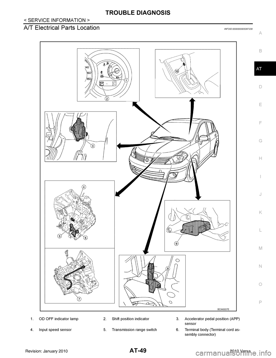
A/T Electrical Parts LocationINFOID:0000000005397238
1. OD OFF indicator lamp 2. Shift position indicator3. Accelerator pedal position (APP)
sensor
4. Input speed sensor 5. Transmission range switch6. Terminal body (Terminal cord as-
sembly connector)
BCIA0037E
Revision: January 20102010 Versa
Page 68 of 3745
TROUBLE DIAGNOSISAT-51
< SERVICE INFORMATION >
DE
F
G H
I
J
K L
M A
B
AT
N
O P
Inspections Before Trouble DiagnosisINFOID:0000000005397240
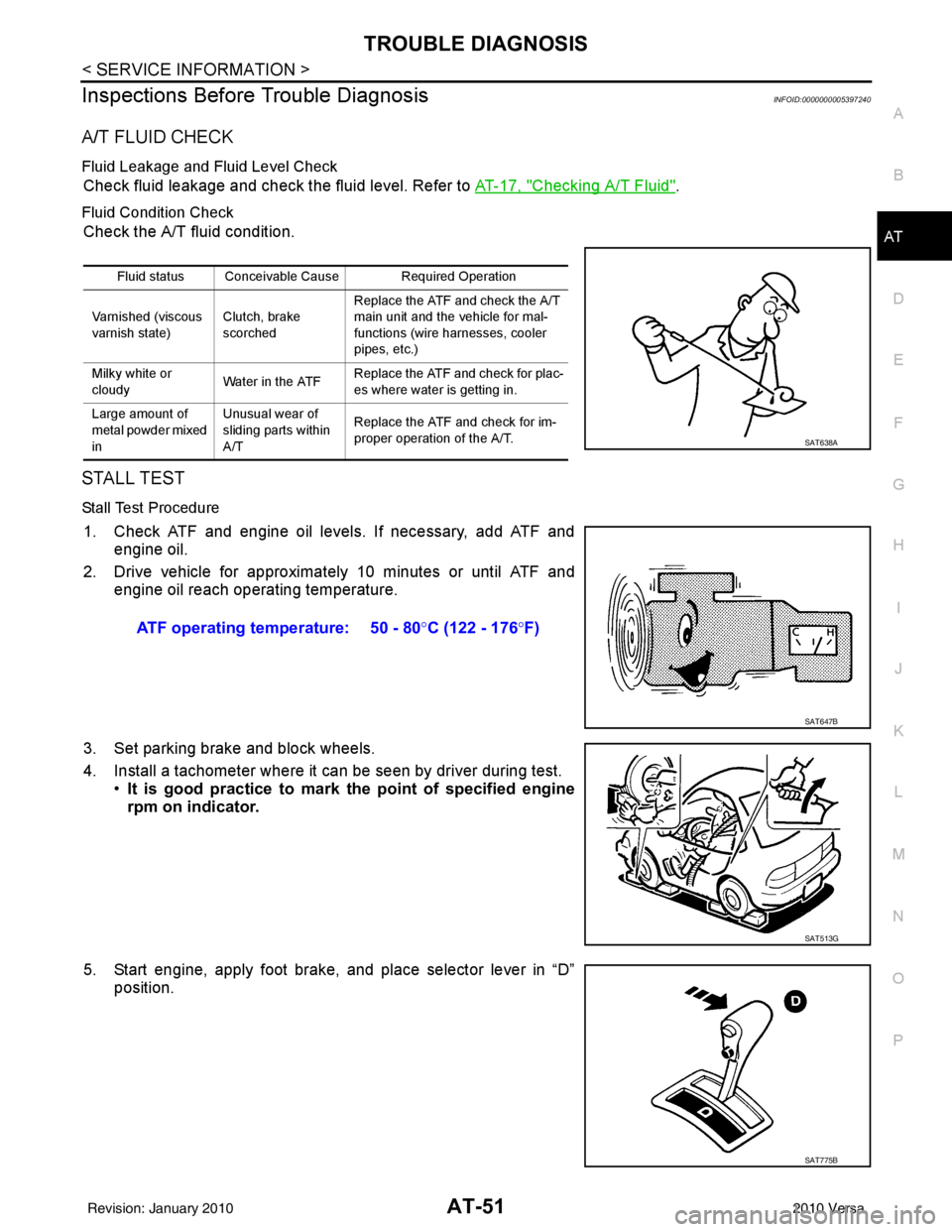
A/T FLUID CHECK
Fluid Leakage and Fluid Level Check
Check fluid leakage and check the fluid level. Refer to AT-17, "Checking A/T Fluid".
Fluid Condition Check
Check the A/T fluid condition.
STALL TEST
Stall Test Procedure
1. Check ATF and engine oil levels. If necessary, add ATF and engine oil.
2. Drive vehicle for approximately 10 minutes or until ATF and engine oil reach operating temperature.
3. Set parking brake and block wheels.
4. Install a tachometer where it can be seen by driver during test. •It is good practice to mark the point of specified engine
rpm on indicator.
5. Start engine, apply foot brake, and place selector lever in “D” position.
Fluid status Conceivable Cause Required Operation
Varnished (viscous
varnish state) Clutch, brake
scorchedReplace the ATF and check the A/T
main unit and the vehicle for mal-
functions (wire harnesses, cooler
pipes, etc.)
Milky white or
cloudy Water in the ATFReplace the ATF and check for plac-
es where water is getting in.
Large amount of
metal powder mixed
in Unusual wear of
sliding parts within
A/T
Replace the ATF and check for im-
proper operation of the A/T.
SAT638A
ATF operating temperature: 50 - 80
°C (122 - 176 °F)
SAT647B
SAT513G
SAT775B
Revision: January 20102010 Versa