2010 NISSAN TIIDA power
[x] Cancel search: powerPage 93 of 3745
AT-76
< SERVICE INFORMATION >
TROUBLE DIAGNOSIS
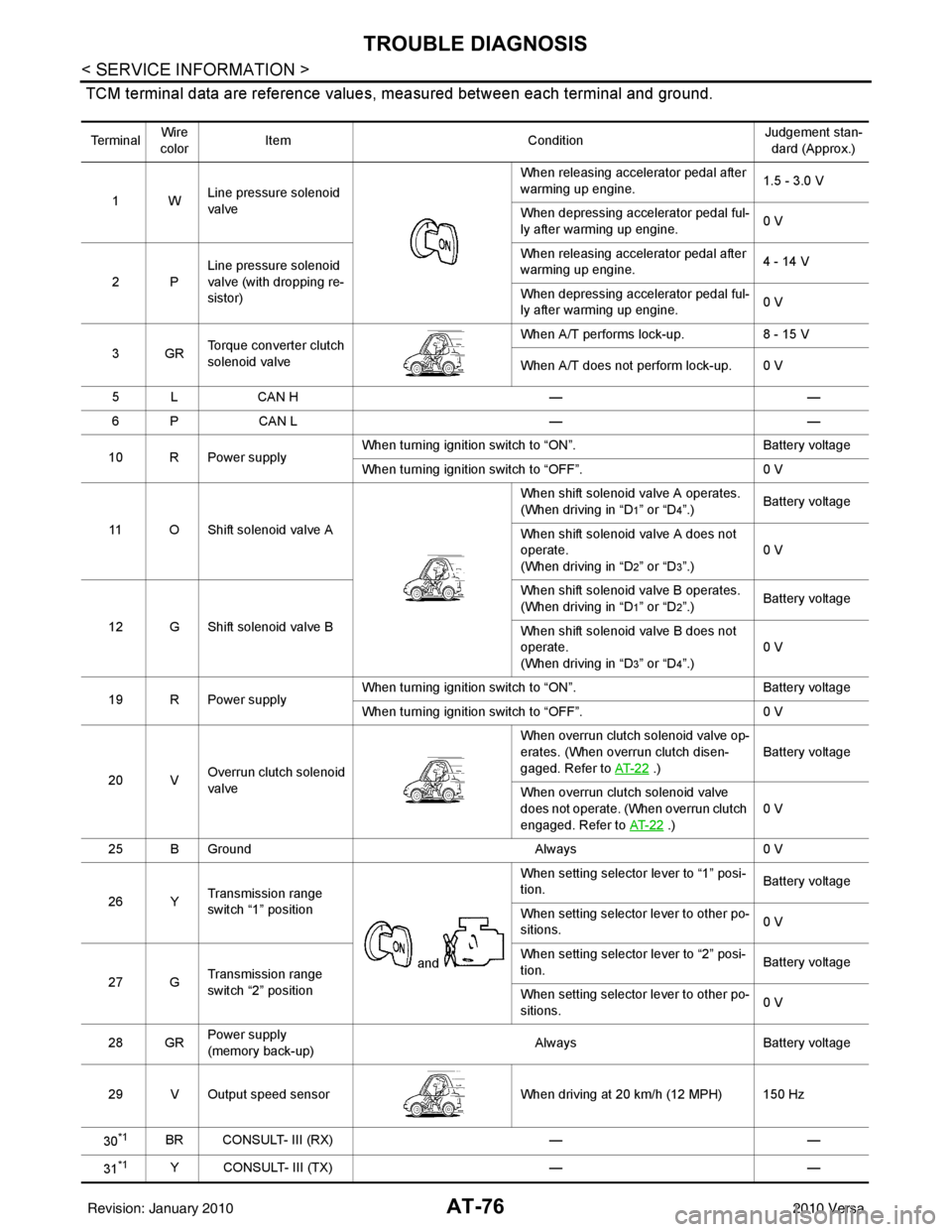
TCM terminal data are reference values, measured between each terminal and ground.
Te r m i n a lWire
color Item
ConditionJudgement stan-
dard (Approx.)
1W Line pressure solenoid
valve When releasing accelerator pedal after
warming up engine.
1.5 - 3.0 V
When depressing accelerator pedal ful-
ly after warming up engine. 0 V
2P Line pressure solenoid
valve (with dropping re-
sistor) When releasing accelerator pedal after
warming up engine.
4 - 14 V
When depressing accelerator pedal ful-
ly after warming up engine. 0 V
3GR Torque converter clutch
solenoid valve When A/T performs lock-up.
8 - 15 V
When A/T does not perform lock-up. 0 V
5 L CAN H ——
6 P CAN L ——
10 R Power supply When turning ignition switch to “ON”.
Battery voltage
When turning ignition switch to “OFF”. 0 V
11 O Shift solenoid valve A When shift solenoid valve A operates.
(When driving in “D
1” or “D4”.)
Battery voltage
When shift solenoid valve A does not
operate.
(When driving in “D
2” or “D3”.) 0 V
12 G Shift solenoid valve B When shift solenoid valve B operates.
(When driving in “D
1” or “D2”.)
Battery voltage
When shift solenoid valve B does not
operate.
(When driving in “D
3” or “D4”.) 0 V
19 R Power supply When turning ignition switch to “ON”.
Battery voltage
When turning ignition switch to “OFF”. 0 V
20 V Overrun clutch solenoid
valve When overrun clutch solenoid valve op-
erates. (When overrun clutch disen-
gaged. Refer to
AT- 2 2
.) Battery voltage
When overrun clutch solenoid valve
does not operate. (When overrun clutch
engaged. Refer to AT- 2 2
.)0 V
25 B Ground Always0 V
26 Y Transmission range
switch “1” position
and When setting selector lever to “1” posi-
tion.
Battery voltage
When setting selector lever to other po-
sitions. 0 V
27 G Transmission range
switch “2” position When setting selector lever to “2” posi-
tion.
Battery voltage
When setting selector lever to other po-
sitions. 0 V
28 GR Power supply
(memory back-up) Always
Battery voltage
29 V Output speed sensor When driving at 20 km/h (12 MPH) 150 Hz
30
*1BR CONSULT- III (RX) ——
31
*1Y CONSULT- III (TX) ——
Revision: January 20102010 Versa
Page 98 of 3745
TROUBLE DIAGNOSISAT-81
< SERVICE INFORMATION >
DE
F
G H
I
J
K L
M A
B
AT
N
O P
CAN DIAGNOSTIC SUPPORT MONITOR MODE
Refer to LAN-14, "CAN Diagnostic Support Monitor".
DTC & SRT CONFIRMATION
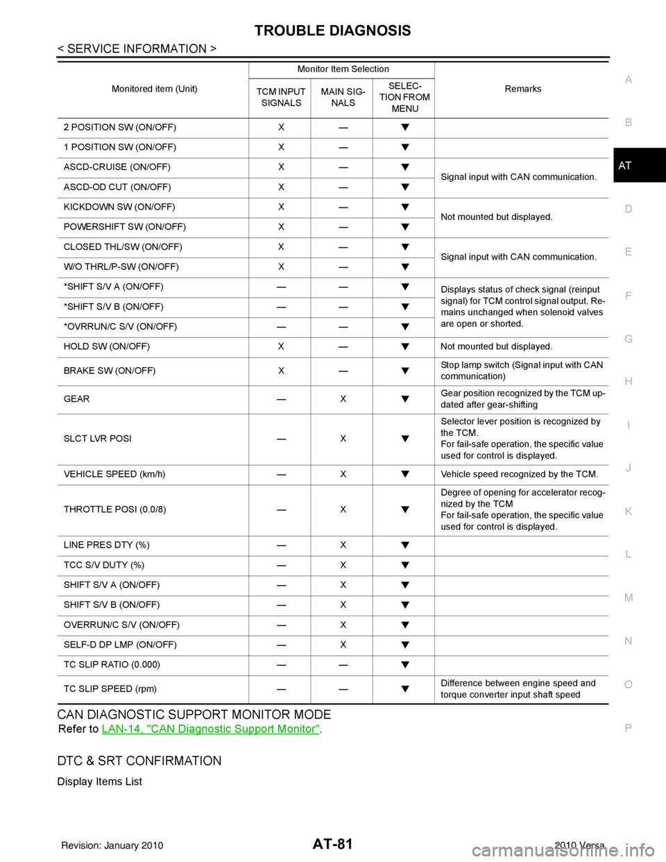
Display Items List
2 POSITION SW (ON/OFF) X—
1 POSITION SW (ON/OFF) X—
ASCD-CRUISE (ON/OFF) X—
Signal input with CAN communication.
ASCD-OD CUT (ON/OFF) X—
KICKDOWN SW (ON/OFF) X—
Not mounted but displayed.
POWERSHIFT SW (ON/OFF) X—
CLOSED THL/SW (ON/OFF) X—
Signal input with CAN communication.
W/O THRL/P-SW (ON/OFF) X—
*SHIFT S/V A (ON/OFF) ——
Displays status of check signal (reinput
signal) for TCM control signal output. Re-
mains unchanged when solenoid valves
are open or shorted.
*SHIFT S/V B (ON/OFF)
——
*OVRRUN/C S/V (ON/OFF) ——
HOLD SW (ON/OFF) X— Not mounted but displayed.
BRAKE SW (ON/OFF) X— Stop lamp switch (Signal input with CAN
communication)
GEAR —X Gear position recognized by the TCM up-
dated after gear-shifting
SLCT LVR POSI —X Selector lever position is recognized by
the TCM.
For fail-safe operation, the specific value
used for control is displayed.
VEHICLE SPEED (km/h) —X Vehicle speed reco gnized by the TCM.
THROTTLE POSI (0.0/8) —X Degree of opening for accelerator recog-
nized by the TCM
For fail-safe operation, the specific value
used for control is displayed.
LINE PRES DTY (%) —X
TCC S/V DUTY (%) —X
SHIFT S/V A (ON/OFF) —X
SHIFT S/V B (ON/OFF) —X
OVERRUN/C S/V (ON/OFF) —X
SELF-D DP LMP (ON/OFF) —X
TC SLIP RATIO (0.000) ——
TC SLIP SPEED (rpm) —— Difference between engine speed and
torque converter input shaft speed
Monitored item (Unit)
Monitor Item Selection
Remarks
TCM INPUT
SIGNALS MAIN SIG-
NALS SELEC-
TION FROM
MENU
Revision: January 20102010 Versa
Page 102 of 3745
TROUBLE DIAGNOSISAT-85
< SERVICE INFORMATION >
DE
F
G H
I
J
K L
M A
B
AT
N
O P
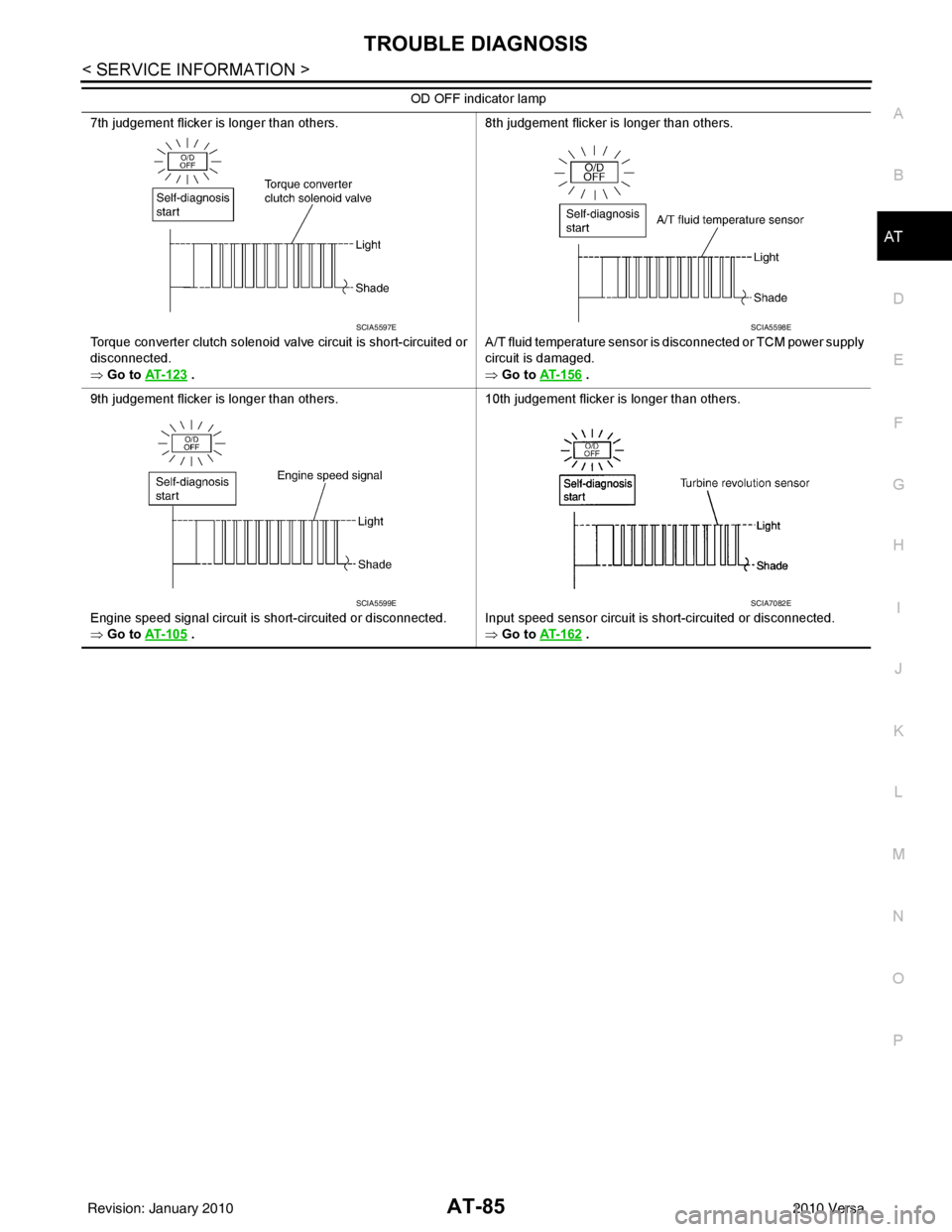
7th judgement flicker is longer than others.
Torque converter clutch solenoid valve circuit is short-circuited or
disconnected.
⇒ Go to AT- 1 2 3
. 8th judgement flicker is longer than others.
A/T fluid temperature sensor is disconnected or TCM power supply
circuit is damaged.
⇒ Go to
AT- 1 5 6 .
9th judgement flicker is longer than others.
Engine speed signal circuit is short-circuited or disconnected.
⇒ Go to AT- 1 0 5
. 10th judgement flicker is longer than others.
Input speed sensor circuit is short-circuited or disconnected.
⇒ Go to
AT- 1 6 2 .
OD OFF indicator lamp
SCIA5597ESCIA5598E
SCIA5599ESCIA7082E
Revision: January 20102010 Versa
Page 115 of 3745
AT-98
< SERVICE INFORMATION >
P0710 TRANSMISSION FLUID TEMPERATURE SENSOR A
3. Check continuity between terminal cord assembly harness con-
nector terminal and TCM connector terminal.
4. If OK, check harness for short to ground and short to power.
5. If OK, check continuity bet ween ground and transaxle assembly.
6. Reinstall any part removed.
OK or NG
OK >> GO TO 5.
NG >> Repair open circuit or short to ground or short to power in harness or connectors.
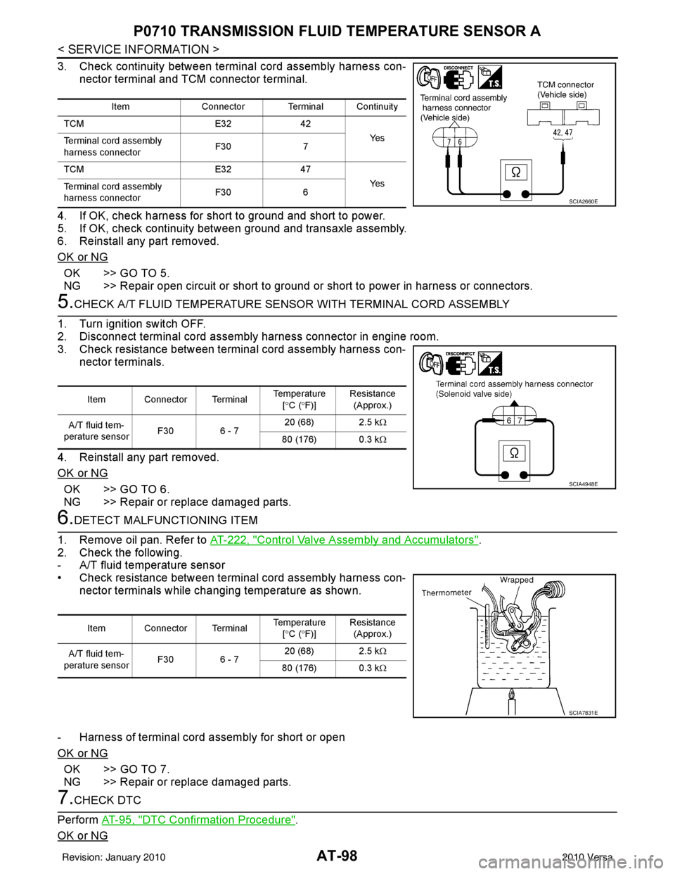
5.CHECK A/T FLUID TEMPERATURE SENSO R WITH TERMINAL CORD ASSEMBLY
1. Turn ignition switch OFF.
2. Disconnect terminal cord assembly harness connector in engine room.
3. Check resistance between terminal cord assembly harness con- nector terminals.
4. Reinstall any part removed.
OK or NG
OK >> GO TO 6.
NG >> Repair or replace damaged parts.
6.DETECT MALFUNCTIONING ITEM
1. Remove oil pan. Refer to AT-222, "
Control Valve Assembly and Accumulators".
2. Check the following.
- A/T fluid temperature sensor
• Check resistance between terminal cord assembly harness con- nector terminals while changing temperature as shown.
- Harness of terminal cord assembly for short or open
OK or NG
OK >> GO TO 7.
NG >> Repair or replace damaged parts.
7.CHECK DTC
Perform AT-95, "
DTC Confirmation Procedure".
OK or NG
Item Connector Terminal Continuity
TCM E3242
Ye s
Terminal cord assembly
harness connector F30
7
TCM E3247
Ye s
Terminal cord assembly
harness connector F30
6
SCIA2660E
Item Connector Terminal Temperature
[° C ( °F)] Resistance
(Approx.)
A/T fluid tem-
perature sensor F30 6 - 7 20 (68) 2.5 k
Ω
80 (176) 0.3 kΩ
SCIA4948E
Item Connector Terminal Temperature
[° C ( °F)] Resistance
(Approx.)
A/T fluid tem-
perature sensor F30 6 - 7 20 (68) 2.5 k
Ω
80 (176) 0.3 kΩ
SCIA7831E
Revision: January 20102010 Versa
Page 119 of 3745
AT-102
< SERVICE INFORMATION >
P0720 OUTPUT SPEED SENSOR
TCM TERMINALS AND REFERENCE VALUES
Refer to AT-75, "TCM Terminal and Reference Value".
Diagnosis ProcedureINFOID:0000000005397281
1.CHECK INPUT SIGNAL
With CONSULT-III
1. Start engine.
2. Select “TCM INPUT SIGNALS” in “DATA MONITOR” mode for “TRANSMISSION” with CONSULT-III.
3. Read out the value of “VHCL/S SE-A/T” while driving. Check the value changes according to driving speed.
OK or NG
OK >> GO TO 8.
NG >> GO TO 2.
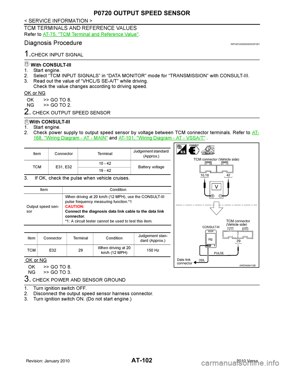
2. CHECK OUTPUT SPEED SENSOR
With CONSULT-III
1. Start engine.
2. Check power supply to output speed sensor by voltage between TCM connector terminals. Refer to AT-
168, "Wiring Diagram - AT - MAIN" and AT-101, "Wiring Diagram - AT - VSSA/T" .
3. If OK, check the pulse when vehicle cruises.
OK or NG
OK >> GO TO 8.
NG >> GO TO 3.
3. CHECK POWER AND SENSOR GROUND
1. Turn ignition switch OFF.
2. Disconnect the output speed sensor harness connector.
3. Turn ignition switch ON. (Do not start engine.)
Item Connector TerminalJudgement standard
(Approx.)
TCM E31, E32 10 - 42
Battery voltage
19 - 42
Item Condition
Output speed sen-
sor When driving at 20 km/h (12 MPH), use the CONSULT-III
pulse frequency measuring function.*1
CAUTION:
Connect the diagnosis
data link cable to the data link
connector.
*1: A circuit tester cannot be used to test this item.
Item Connector Terminal Condition Judgement stan-
dard (Approx.)
TCM E32 29When driving at 20
km/h (12 MPH) 150 Hz
AWDIA0641GB
Revision: January 20102010 Versa
Page 120 of 3745
P0720 OUTPUT SPEED SENSORAT-103
< SERVICE INFORMATION >
DE
F
G H
I
J
K L
M A
B
AT
N
O P
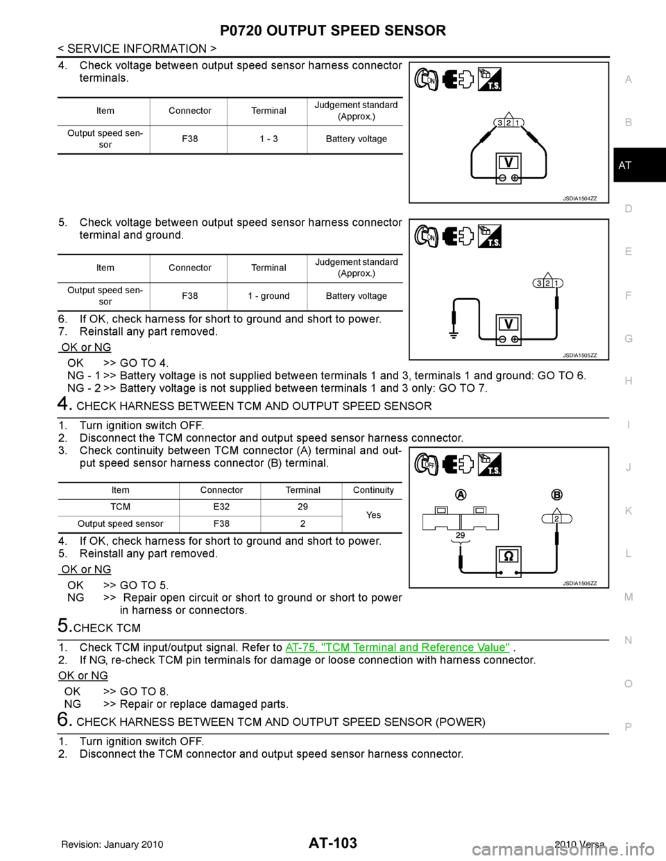
4. Check voltage between output speed sensor harness connector terminals.
5. Check voltage between output speed sensor harness connector terminal and ground.
6. If OK, check harness for short to ground and short to power.
7. Reinstall any part removed.
OK or NG
OK >> GO TO 4.
NG - 1 >> Battery voltage is not supplied between terminals 1 and 3, terminals 1 and ground: GO TO 6.
NG - 2 >> Battery voltage is not supplied between terminals 1 and 3 only: GO TO 7.
4. CHECK HARNESS BETWEEN TCM AND OUTPUT SPEED SENSOR
1. Turn ignition switch OFF.
2. Disconnect the TCM connector and output speed sensor harness connector.
3. Check continuity between TCM connector (A) terminal and out- put speed sensor harness connector (B) terminal.
4. If OK, check harness for short to ground and short to power.
5. Reinstall any part removed.
OK or NG
OK >> GO TO 5.
NG >> Repair open circuit or short to ground or short to power in harness or connectors.
5.CHECK TCM
1. Check TCM input/output signal. Refer to AT-75, "
TCM Terminal and Reference Value" .
2. If NG, re-check TCM pin terminals for dam age or loose connection with harness connector.
OK or NG
OK >> GO TO 8.
NG >> Repair or replace damaged parts.
6. CHECK HARNESS BETWEEN TCM AND OUTPUT SPEED SENSOR (POWER)
1. Turn ignition switch OFF.
2. Disconnect the TCM connector and output speed sensor harness connector.
Item Connector Terminal Judgement standard
(Approx.)
Output speed sen- sor F38
1 - 3Battery voltage
JSDIA1504ZZ
Item Connector Terminal Judgement standard
(Approx.)
Output speed sen- sor F38
1 - ground Battery voltage
JSDIA1505ZZ
Item Connector Terminal Continuity
TCM E3229
Ye s
Output speed sensor F382
JSDIA1506ZZ
Revision: January 20102010 Versa
Page 121 of 3745
AT-104
< SERVICE INFORMATION >
P0720 OUTPUT SPEED SENSOR
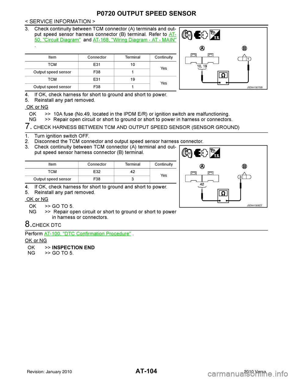
3. Check continuity between TCM connector (A) terminals and out-put speed sensor harness connector (B) terminal. Refer to AT-
50, "Circuit Diagram" and AT-168, "Wiring Diagram - AT - MAIN"
.
4. If OK, check harness for short to ground and short to power.
5. Reinstall any part removed.
OK or NG
OK >> 10A fuse (No.49, located in the IPDM E/R) or ignition switch are malfunctioning.
NG >> Repair open circuit or short to ground or short to power in harness or connectors.
7. CHECK HARNESS BETWEEN TCM AND OUTPUT SPEED SENSOR (SENSOR GROUND)
1. Turn ignition switch OFF.
2. Disconnect the TCM connector and output speed sensor harness connector.
3. Check continuity between TCM connector (A) terminal and out-
put speed sensor harness connector (B) terminal.
4. If OK, check harness for short to ground and short to power.
5. Reinstall any part removed.
OK or NG
OK >> GO TO 5.
NG >> Repair open circuit or short to ground or short to power in harness or connectors.
8.CHECK DTC
Perform AT-100, "
DTC Confirmation Procedure" .
OK or NG
OK >> INSPECTION END
NG >> GO TO 5.
Item Connector Terminal Continuity
TCM E3110
Ye s
Output speed sensor F381
TCM E3119
Ye s
Output speed sensor F381
JSDIA1507GB
Item Connector Terminal Continuity
TCM E3242
Ye s
Output speed sensor F383
JSDIA1508ZZ
Revision: January 20102010 Versa
Page 124 of 3745
P0725 ENGINE SPEEDAT-107
< SERVICE INFORMATION >
DE
F
G H
I
J
K L
M A
B
AT
N
O P
Diagnosis ProcedureINFOID:0000000005397288
1.CHECK DTC WITH ECM
Check DTC with CONSULT-III “ENGINE”.
Turn ignition switch ON and select “SELF-DIAGNOST IC RESULTS” mode for “ENGINE” with CONSULT-III.
Refer to EC-98, "
CONSULT-III Function" (HR16DE), EC-612, "CONSULT-III Function (ENGINE)" (MR18DE).
OK or NG
OK >> GO TO 2.
NG >> Check ignition signal circuit for engine control. Refer to EC-432, "
Description" (HR16DE), EC-
1019, "Component Description" (MR18DE).
2.CHECK INPUT SIGNAL
With CONSULT-III
1. Start engine.
2. Select “TCM INPUT SIGNALS” in “DATA MONI TOR” mode for “TRANSMISSION” with CONSULT-III.
3. Read out the value of “ENGINE SPEED”. Check engine speed changes according to throttle position.
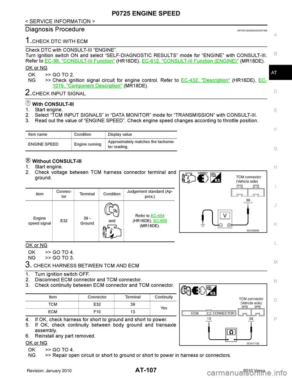
Without CONSULT-III
1. Start engine.
2. Check voltage between TCM harness connector terminal and ground.
OK or NG
OK >> GO TO 4.
NG >> GO TO 3.
3. CHECK HARNESS BETWEEN TCM AND ECM
1. Turn ignition switch OFF.
2. Disconnect ECM connector and TCM connector.
3. Check continuity between ECM connector and TCM connector.
4. If OK, check harness for short to ground and short to power.
5. If OK, check continuity between body ground and transaxle
assembly.
6. Reinstall any part removed.
OK or NG
OK >> GO TO 4.
NG >> Repair open circuit or short to ground or short to power in harness or connectors.
Item name Condition Display value
ENGINE SPEED Engine running Approximately matches the tachome-
ter reading.
itemConnec-
tor Terminal Condition Judgement standard (Ap-
prox.)
Engine
speed signal E3239 -
Ground
and Refer to EC-454
(HR16DE), EC-605
(MR18DE).
SCIA3265E
Item Connector Terminal Continuity
TCM E3239
Ye s
ECM F1013
SCIA7173E
Revision: January 20102010 Versa