2010 NISSAN TIIDA manual air conditioner
[x] Cancel search: manual air conditionerPage 1 of 3745

-1
QUICK REFERENCE INDEX
AGENERAL INFORMATIONGIGeneral Information
BENGINEEMEngine Mechanical
LUEngine Lubrication System
COEngine Cooling System
ECEngine Control System
FLFuel System
EXExhaust System
ACCAccelerator Control System
CTRANSMISSION/
TRANSAXLECLClutch System
MTManual Transaxle
ATAutomatic Transaxle
CVTCVT
DDRIVELINE/AXLEFAXFront Axle
RAXRear Axle
ESUSPENSIONFSUFront Suspension
RSURear Suspension
WTRoad Wheels & Tires
FBRAKESBRBrake System
PBParking Brake System
BRCBrake Control System
GSTEERINGPSPower Steering System
STCSteering Control System
HRESTRAINTSSBSeat Belts
SRSSupplemental Restraint System (SRS)
IBODYBLBody, Lock & Security System
GWGlasses, Window System & Mirrors
RFRoof
EIExterior & Interior
IPInstrument Panel
SESeat
JAIR CONDITIONERMTCManual Air Conditioner
KELECTRICALSCStarting & Charging System
LTLighting System
DIDriver Information System
WWWiper, Washer & Horn
BCSBody Control System
LANLAN System
AVAudio Visual, Navigation & Telephone System
ACSAuto Cruise Control System
PGPower Supply, Ground & Circuit Elements
LMAINTENANCEMAMaintenance
Edition: September 2009
Revision: January 2010
Publication No. SM0E-1C11U1
B
D
© 2010 NISSAN NORTH AMERICA, INC.
All rights reserved. No part of this Service Manual may be reproduced or stored in a retrieval system, or transmitted in any
form, or by any means, electronic, mechanical, photo-copying, recording or otherwise, without the prior written permission
of Nissan North America Inc.
A
C
E
F
G
H
I
J
K
L
M
Page 2686 of 3745
GI-20
< SERVICE INFORMATION >
HOW TO USE THIS MANUAL
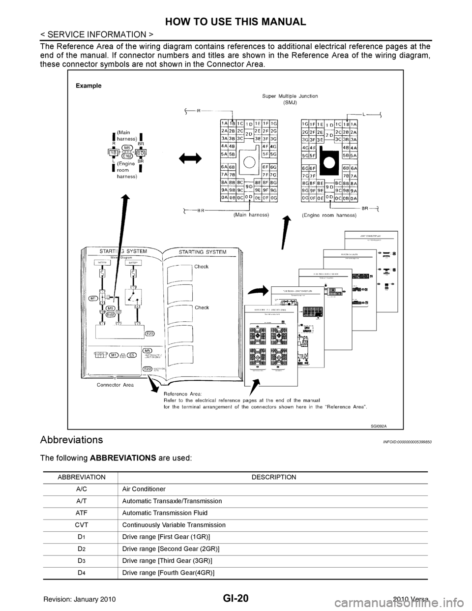
The Reference Area of the wiring diagram contains references to additional electrical reference pages at the
end of the manual. If connector numbers and titles are shown in the Reference Area of the wiring diagram,
these connector symbols are not shown in the Connector Area.
AbbreviationsINFOID:0000000005399850
The following ABBREVIATIONS are used:
SGI092A
ABBREVIATION DESCRIPTION
A/C Air Conditioner
A/T Automatic Transaxle/Transmission
ATF Automatic Transmission Fluid
CVT Continuously Variable Transmission
D
1Drive range [First Gear (1GR)]
D
2Drive range [Second Gear (2GR)]
D
3Drive range [Third Gear (3GR)]
D
4Drive range [Fourth Gear(4GR)]
Revision: January 20102010 Versa
Page 2710 of 3745
GI-44
< SERVICE INFORMATION >
IDENTIFICATION INFORMATION
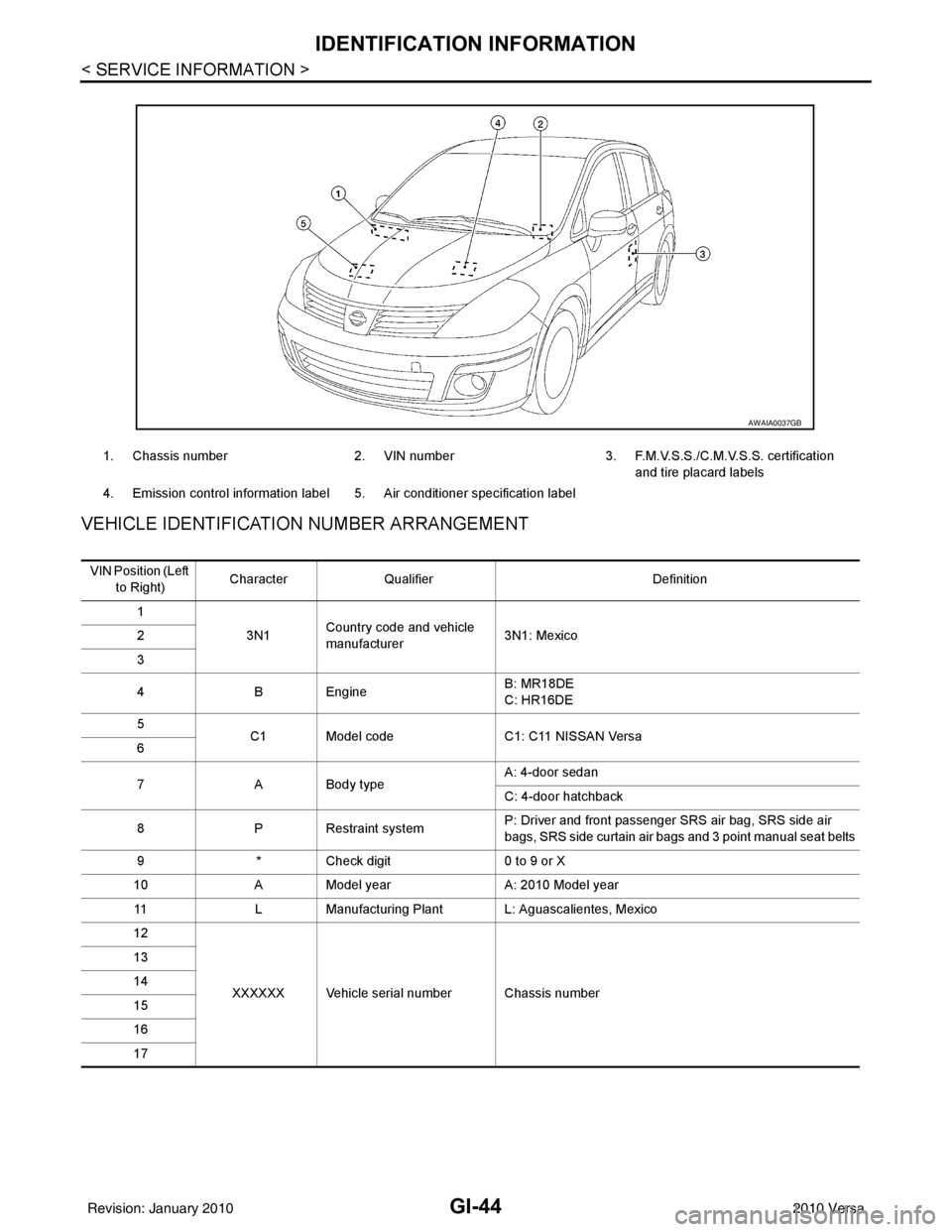
VEHICLE IDENTIFICATION NUMBER ARRANGEMENT
1. Chassis number 2. VIN number 3. F.M.V.S.S./C.M.V.S.S. certification
and tire placard labels
4. Emission control information label 5. Air conditioner specification label
AWAIA0037GB
VIN Position (Left to Right) Character
Qualifier Definition
1 3N1Country code and vehicle
manufacturer 3N1: Mexico
2
3
4 B Engine B: MR18DE
C: HR16DE
5 C1 Model code C1: C11 NISSAN Versa
6
7 A Body type A: 4-door sedan
C: 4-door hatchback
8 P Restraint system P: Driver and front passenger SRS air bag, SRS side air
bags, SRS side curtain air bags and 3 point manual seat belts
9 * Check digit 0 to 9 or X
10 A Model year A: 2010 Model year
11 L Manufacturing Plant L: Aguascalientes, Mexico
12
XXXXXX Vehicle serial number Chassis number
13
14
15
16
17
Revision: January 20102010 Versa
Page 3149 of 3745

MA-14
< SERVICE INFORMATION >
RECOMMENDED FLUIDS AND LUBRICANTS
RECOMMENDED FLUIDS AND LUBRICANTS
Fluids and LubricantsINFOID:0000000005394798
*1: For further details, see “Engine Oil Recommendation”.
*2: If genuine NISSAN gear oil is not available, API GL-4, Viscosity SAE 75W-80 may be used as a temporary replacement. However
use Genuine NISSAN gear oil as soon as it is possible.
*3: Using transaxle fluid other than Genuine NISSAN CVT Fluid NS-2 will damage the CVT, which is not covered by the NISSAN
new vehicle limited warranty.
*4: Available in mainland U.S.A. through a NISSAN dealer.
*5: For further details, see “Air conditioner specification label”.
*6: If Genuine NISSAN Matic S ATF is not available, Genuine NISSIAN Matic D ATF may also be used. Using automatic transmission
other than Genuine NISSAN Matic S or Genuine NISSIAN Matic D ATF will cause deteri oration in driveability and automatic transmis-
sion durability, and may damage the automatic transmission, which is not covered by NISSAN new vehicle limited warranty.
SAE Viscosity NumberINFOID:0000000005394799
NISSAN recommends the use of an energy conservi ng oil in order to improve fuel economy.
DescriptionCapacity (Approximate)
Recommended Fluids/Lubricants
Liter US measure Imp measure
Fuel 50.0 13 1/4 gal 11 galUnleaded gasoline with an octane rat-
ing of at least 87 AKI (RON 91)
Engine oil
Drain and refill With oil filter
change
HR16DE 3.0 3 1/8 qt 2 5/8 qt
• Engine oil with API Certification Mark *1
• Viscosity SAE 5W-30
MR18DE 4.1 4 3/8 qt 3 5/8 qt
Without oil
filter change HR16DE 2.8
3 qt 2 1/2 qt
MR18DE 3.9 4 1/8 qt 3 3/8 qt
Dry engine (engine overhaul) HR16DE 3.5 3 3/4 qt 3 1/8 qt
MR18DE 4.9 5 1/8 qt 4 3/8 qt
Cooling system
(with reservoir at max level) HR16DE 6.3 6 5/8 qt 5 1/2 qt Genuine
NISSAN Long Life Anti-freeze
Coolant or equivalent
MR18DE 6.8 7 1/4 qt 6 qt
Manual transaxle fluid (MTF) 5MT
2.6 5 1/2 pt 4 5/8 pt Genuine NISSAN Manual Transmis-
sion Fluid (MTF) HQ Multi 75W-85 or
API GL-4, Viscosity SAE 75W-85
6MT 2.0 4 1/4 pt 3 1/2 pt Genuine NISSAN gear oil (XT4447
M+) 75W-80, Genuine NISSAN gear oil
(ETL8997B) 75W-80, or equivalent *2
Automatic transaxle fluid (ATF) HR16DE 7.7 8 1/8 qt 6 3/4 qt
Genuine NISSAN Matic S ATF recom-
mended *6
MR18DE 7.9 8 3/8 qt 7 qt
CVT fluid RE0F08B 7.4 7 7/8 qt 6 1/2 qt Genuine NISSAN CVT Fluid NS-2 *3
Brake and clutch fluid ———Genuine NISSAN Su
per Heavy Duty
Brake Fluid*4 or equivalent DOT 3 (US
FMVSS No. 116)
Multi-purpose grease ——— NLGI No. 2 (Lithium soap base)
Windshield washer fluid 4.5 4 3/4 qt 4 qtGenuine NISSAN Windshield Washer
Concentrate Cleaner & Anti-Freeze or
equivalent
Air conditioning system refrigerant 0.45 ± 0.05 kg 0.99 ± 0.11 lb 0.99 ± 0.11 lb HFC-134a (R-134a) *5
Air conditioning system oil MR18DE
Type 1 and
HR16DE
120 m
4.1 fl oz 4.2 fl oz NISSAN A/C System Lubricant Type R
or equivalent *5
MR18DE
Typ e 2 100 m
3.4 fl oz 3.5 fl oz NISSAN A/C System Lubricant Type S
or equivalent *5
Revision: January 20102010 Versa
Page 3280 of 3745

MTC-1
AIR CONDITIONER
C
DE
F
G H
I
K L
M
SECTION MTC
A
B
MTC
N
O P
CONTENTS
MANUAL AIR CONDITIONER
SERVICE INFORMATION .. ..........................3
PRECAUTIONS .............................................. .....3
Precaution for Supplemental Restraint System
(SRS) "AIR BAG" and "SEAT BELT PRE-TEN-
SIONER" ............................................................. ......
3
Precaution Necessary for Steering Wheel Rota-
tion After Battery Disconnect ............................... ......
3
Precaution for Procedure without Cowl Top Cover ......4
Precaution for Working with HFC-134a (R-134a) ......4
General Refrigerant Precaution ................................4
Oil Precaution ............................................................5
Precaution for Refrigerant Connection ......................5
Precaution for Service of Compressor ................ ......7
Precaution for Service Equipment ....................... ......8
Precaution for Leak Detection Dye ...........................9
PREPARATION ..................................................11
HFC-134a (R-134a) Service Tool and Equipment ....11
Commercial Service Tool ........................................14
REFRIGERATION SYSTEM ..............................15
Refrigerant Cycle ................................................ ....15
Refrigerant System Protection ................................15
Component Part Location ................................... ....16
OIL ......................................................................17
Maintenance of Oil Quantity in Compressor ....... ....17
AIR CONDITIONER CONTROL .........................19
Control Operation ................................................ ....19
Discharge Air Flow ..................................................20
System Description .................................................20
TROUBLE DIAGNOSIS .....................................22
CONSULT-III Function (BCM) ............................. ....22
How to Perform Trouble Diagnosis for Quick and
Accurate Repair ......................................................
23
Component Parts and Harness Connector Loca-
tion ...................................................................... ....
23
Schematic ...............................................................26
Wiring Diagram - Heater - .......................................27
Wiring Diagram - A/C,M - .................................... ....28
Operational Check ...................................................31
Mode Door ...............................................................32
Air Mix Door .............................................................33
Intake Door ..............................................................34
Front Blower Motor Circuit .......................................34
Magnet Clutch Circuit (If Equipped) ..................... ....38
Insufficient Cooling ..................................................46
Insufficient Heating ..................................................53
Noise .......................................................................54
CONTROLLER ..................................................56
Removal and Installation .........................................56
Disassembly and Assembly .....................................57
THERMO CONTROL AMPLIFIER ....................58
Removal and Installation .........................................58
A/C UNIT ASSEMBLY ......................................59
Removal and Installation .........................................59
Disassembly and Assembly .....................................61
BLOWER MOTOR ............................................63
Removal and Installation .........................................63
INTAKE DOOR ..................................................64
Intake Door Cable Adjustment .................................64
AIR MIX DOOR .................................................65
Air Mix Door Cable Adjustment ...............................65
MODE DOOR ....................................................66
Mode Door Cable Adjustment .................................66
BLOWER FAN RESISTOR ...............................67
Removal and Installation .........................................67
HEATER CORE .................................................68
Removal and Installation .........................................68
AIR CONDITIONER FILTER .............................69
Removal and Installation .........................................69
Revision: January 20102010 Versa
Page 3442 of 3745

HARNESSPG-59
< SERVICE INFORMATION >
C
DE
F
G H
I
J
L
M A
B
PG
N
O P
Wiring Diagram Codes (Cell Codes)INFOID:0000000005395367
Use the chart below to find out what each wiring diagram code stands for.
Refer to the wiring diagram code in the alphabetical index to find the location (page number) of each wiring
diagram.
D4 D405 W/4 : Back door lock assembly C2 D413 B/1 : Rear window defogger (-)
D4 D406 W/2 : Back door request switch F3 D414 — : Body ground
E2 D407 W/2 : High mounted stop lamp
Code Section Wiring Diagram Name
ABS BRC Anti-lock Brake System
A/C,M MTC Manual Air Conditioner
APPS1 EC Accelerator Pedal Position Sensor
A/F EC Air Fuel Ratio Sensor 1
A/FH EC Air Fuel Ratio Sensor 1 Heater
APPS2 EC Accelerator Pedal Position Sensor
APPS3 EC Accelerator Pedal Position Sensor
ASC/BS EC ASCD Brake Switch
ASC/SW EC ASCD Steering Switch
ASCBOF EC ASCD Brake Switch
ASCIND EC ASCD Indicator
AT/IND DI A/T Indicator Lamp
AUDIO AV Audio
BACK/L LT Back-up Lamp
BA/FTS AT A/T Fluid Temperature Sensor and TCM Power Supply
B/DOOR BL Back Door Opener
BRK/SW EC Brake Switch
CAN AT CAN Communication Line
CAN CVT CAN Communication Line
CAN EC CAN Communication Line
CAN LAN CAN System
CHARGE SC Charging System
CHIME DI Warning Chime
COOL/F EC Cooling Fan Control
COMBSW LT Combination Switch
COMM AV Audio Visual Communication System
CVTIND DI CVT Indicator Lamp
D/LOCK BL Power Door Lock
DEF GW Rear Window Defogger
DTRL LT Headlamp - Wi th Daytime Light System
ECTS EC Engine Coolant Temperature Sensor
ENGSS AT Engine Speed Signal
EPS STC Electronic Controlled Power Steering
ETC1 EC Electric Throttle Control Function
ETC2 EC Throttle Control Motor Relay
ETC3 EC Throttle Control Motor
F/FOG LT Front Fog Lamp
F/PUMP EC Fuel Pump
FTS AT A/T Fluid Temperature Sensor
FTS CVT CVT Fluid Temperature Sensor Circuit
FTTS EC Fuel Tank Temperature Sensor
FUEL EC Fuel Ignition System Function
Revision: January 20102010 Versa