2010 NISSAN TIIDA check engine
[x] Cancel search: check enginePage 1221 of 3745
COMBINATION METERSDI-11
< SERVICE INFORMATION >
C
DE
F
G H
I
J
L
M A
B
DI
N
O P
Self-Diagnosis Mode of Combination MeterINFOID:0000000005395014
SELF-DIAGNOSIS MODE FUNCTION
• Self-diagnosis can check for continuity between meter control circuit and each meter (speedometer, tachom- eter and fuel gauge).
• Self-diagnosis can check for odo/trip meter and A/T indi cator (with A/T) or CVT indicator (with CVT) seg-
ment, low-fuel level warning lamp, low water temperature indicator lamp, and high water temperature warn-
ing lamp.
OPERATION PROCEDURE
1. Turn the ignition switch ON, and switch the odo/trip meter to “trip A” or “trip B”. NOTE:
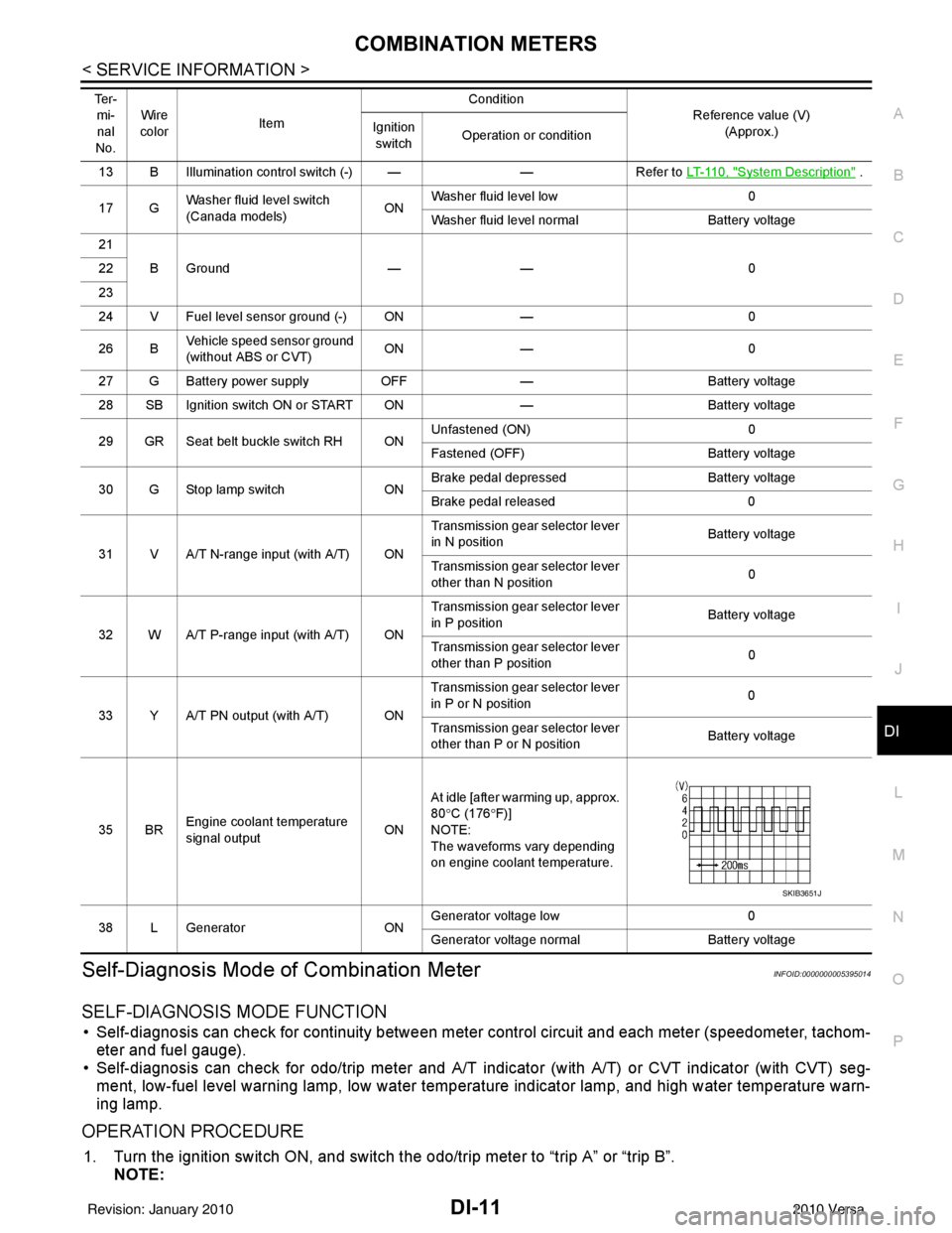
13 B Illumination control switch (-) — —Refer to LT-110, "System Description" .
17 G Washer fluid level switch
(Canada models)
ONWasher fluid level low
0
Washer fluid level normal Battery voltage
21 BGround —— 0
22
23
24 V Fuel level sensor ground (-) ON —0
26 B Vehicle speed sensor ground
(without ABS or CVT) ON
— 0
27 G Battery power supply OFF— Battery voltage
28 SB Ignition switch ON or START ON —Battery voltage
29 GR Seat belt buckle switch RH ON Unfastened (ON)
0
Fastened (OFF) Battery voltage
30 G Stop lamp switch ONBrake pedal depressed
Battery voltage
Brake pedal released 0
31 V A/T N-range input (with A/T) ON Transmission gear selector lever
in N position
Battery voltage
Transmission gear selector lever
other than N position 0
32 W A/T P-range input (with A/T) ON Transmission gear selector lever
in P position
Battery voltage
Transmission gear selector lever
other than P position 0
33 Y A/T PN output (with A/T) ON Transmission gear selector lever
in P or N position
0
Transmission gear selector lever
other than P or N position Battery voltage
35 BR Engine coolant temperature
signal output
ONAt idle [after warming up, approx.
80
°C (176 °F)]
NOTE:
The waveforms vary depending
on engine coolant temperature.
38 L Generator ONGenerator voltage low
0
Generator voltage no rmal Battery voltage
Te r -
mi-
nal
No. Wire
color Item Condition
Reference value (V)
(Approx.)
Ignition
switch Operation or condition
SKIB3651J
Revision: January 20102010 Versa
Page 1225 of 3745
COMBINATION METERSDI-15
< SERVICE INFORMATION >
C
DE
F
G H
I
J
L
M A
B
DI
N
O P
YES >> GO TO 2.
NO >> Check power supply and ground circuit of combination meter. Refer to DI-15, "
Power Supply and
Ground Circuit Inspection" .
2.CHECK COMBINATION METER (CONSULT-III)
Select “METER/M&A” on CONSULT-II I and perform self-diagnosis of combination meter. Refer to DI-13,
"CONSULT-III Function (METER/M&A)" .
Self
-diagnostic results content
No malfunction detected>> Refer to DI-15, "Symptom Chart" .
Malfunction detected>> Refer to DI-13, "
CONSULT-III Function (METER/M&A)" .
Symptom ChartINFOID:0000000005395017
Power Supply and Gro und Circuit InspectionINFOID:0000000005395018
1.CHECK FUSE
Check for blown combination meter fuses.
OK or NG
OK >> GO TO 2.
NG >> Be sure to eliminate cause of malfunction before installing new fuse. Refer to PG-4
.
2.CHECK POWER SUPPLY CIRCUIT
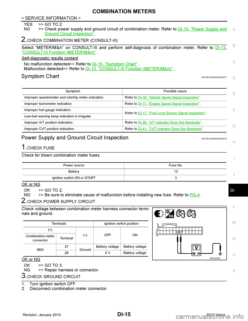
Check voltage between combination meter harness connector termi-
nals and ground.
OK or NG
OK >> GO TO 3.
NG >> Repair harness or connector.
3.CHECK GROUND CIRCUIT
1. Turn ignition switch OFF.
2. Disconnect combination meter connector.
Symptom Possible cause
Improper speedometer and odo/trip meter indication. Refer to DI-16, "
Vehicle Speed Signal Inspection" .
Improper tachometer indication. Refer to DI-17, "
Engine Speed Signal Inspection" .
Improper fuel gauge indication. Refer to DI-17, "
Fuel Level Sensor Signal Inspection" .
Low-fuel warning lamp indication is irregular.
Improper A/T position indication. Refer to DI-36, "
A/T Indicator Does Not Illuminate" .
Improper CVT position indication. Refer to DI-41, "
CVT Indicator Does Not Illuminate" .
Power source Fuse No.
Battery 13
Ignition switch ON or START 3
TerminalsIgnition switch position
(+) (–) OFF ON
Combination meter
connector Te r m i n a l
M24 27
Ground Battery voltage Battery voltage
28 0 V Battery voltage
PKIC0700E
Revision: January 20102010 Versa
Page 1226 of 3745
DI-16
< SERVICE INFORMATION >
COMBINATION METERS
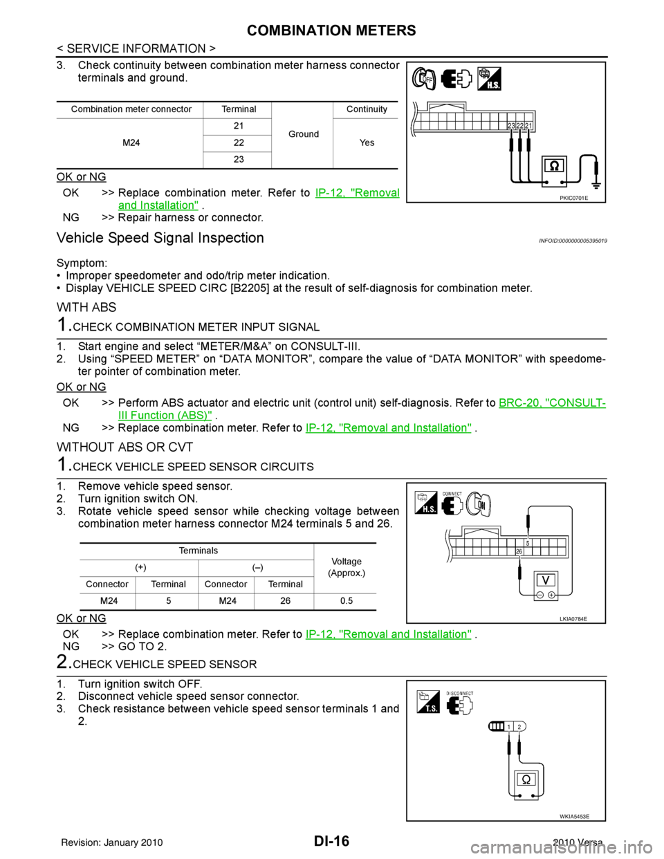
3. Check continuity between combination meter harness connectorterminals and ground.
OK or NG
OK >> Replace combination meter. Refer to IP-12, "Removal
and Installation" .
NG >> Repair harness or connector.
Vehicle Speed Signal InspectionINFOID:0000000005395019
Symptom:
• Improper speedometer and odo/trip meter indication.
• Display VEHICLE SPEED CIRC [B2205] at the result of self-diagnosis for combination meter.
WITH ABS
1.CHECK COMBINATION METER INPUT SIGNAL
1. Start engine and select “METER/M&A” on CONSULT-III.
2. Using “SPEED METER” on “DATA MONITOR”, comp are the value of “DATA MONITOR” with speedome-
ter pointer of combination meter.
OK or NG
OK >> Perform ABS actuator and electric uni t (control unit) self-diagnosis. Refer to BRC-20, "CONSULT-
III Function (ABS)" .
NG >> Replace combination meter. Refer to IP-12, "
Removal and Installation" .
WITHOUT ABS OR CVT
1.CHECK VEHICLE SPEED SENSOR CIRCUITS
1. Remove vehicle speed sensor.
2. Turn ignition switch ON.
3. Rotate vehicle speed sensor while checking voltage between combination meter harness connector M24 terminals 5 and 26.
OK or NG
OK >> Replace combination meter. Refer to IP-12, "Removal and Installation" .
NG >> GO TO 2.
2.CHECK VEHICLE SPEED SENSOR
1. Turn ignition switch OFF.
2. Disconnect vehicle speed sensor connector.
3. Check resistance between vehicle speed sensor terminals 1 and 2.
Combination meter connector Terminal
GroundContinuity
M24 21
Ye s
22
23
PKIC0701E
Te r m i n a l s
Voltag e
(Approx.)
(+)
(–)
Connector Terminal Connector Terminal M24 5M24 26 0.5
LKIA0784E
WKIA5453E
Revision: January 20102010 Versa
Page 1227 of 3745
COMBINATION METERSDI-17
< SERVICE INFORMATION >
C
DE
F
G H
I
J
L
M A
B
DI
N
O P
OK or NG
OK >> Check harness or connector between combination meter and vehicle speed sensor.
NG >> Replace vehicle speed sensor.
WITH CVT, WITHOUT ABS
1.CHECK COMBINATION METER INPUT SIGNAL
1. Start engine and select “M ETER/M&A” on CONSULT-III.
2. Using “SPEED METER” on “DATA MONITOR”, comp are the value of “DATA MONITOR” with speedome-
ter pointer of combination meter.
OK or NG
OK >> Perform TCM self-diagnosis. Refer to CVT-48, "CONSULT-III Function (TRANSMISSION)" .
NG >> Replace combination meter. Refer to IP-12, "
Removal and Installation" .
Engine Speed Signal InspectionINFOID:0000000005395020
Symptom: Improper tachometer indication.
1.CHECK COMBINATION METER INPUT SIGNAL
1. Start engine and select “M ETER/M&A” on CONSULT-III.
2. Using “TACHO METER” on “DATA MONITOR”, compare the value of “DATA MONITOR” with tachometer pointer of combination meter.
OK or NG
OK >> Perform ECM self-diagnosis. Refer to EC-612, "CONSULT-III Function (ENGINE)" (MR18DE) or
EC-98, "
CONSULT-III Function" (HR16DE).
NG >> Replace combination meter. Refer to IP-12, "
Removal and Installation" .
Fuel Level Sensor Signal InspectionINFOID:0000000005395021
Symptom:• Improper fuel gauge indication.
• Low-fuel warning lamp indication is irregular.
NOTE:
The following symptoms do not indicate a malfunction.
• Depending on vehicle position or driving circumstance, the fuel level in the tank shifts and the indication may fluctuate.
• If the vehicle is fueled with the ignition switch ON, the indication will update slowly.
• If the vehicle is tilted when the ignition switch is turned ON, fuel in the tank may flow to one direction result-
ing in a change of reading.
1.CHECK COMBINATION METER INPUT SIGNAL
1. Select “METER/M&A” on CONSULT-III.
2. Using “FUEL METER” on “DATA MONITOR”, compare the value of “DATA MONITOR” with fuel gauge pointer of combination meter.
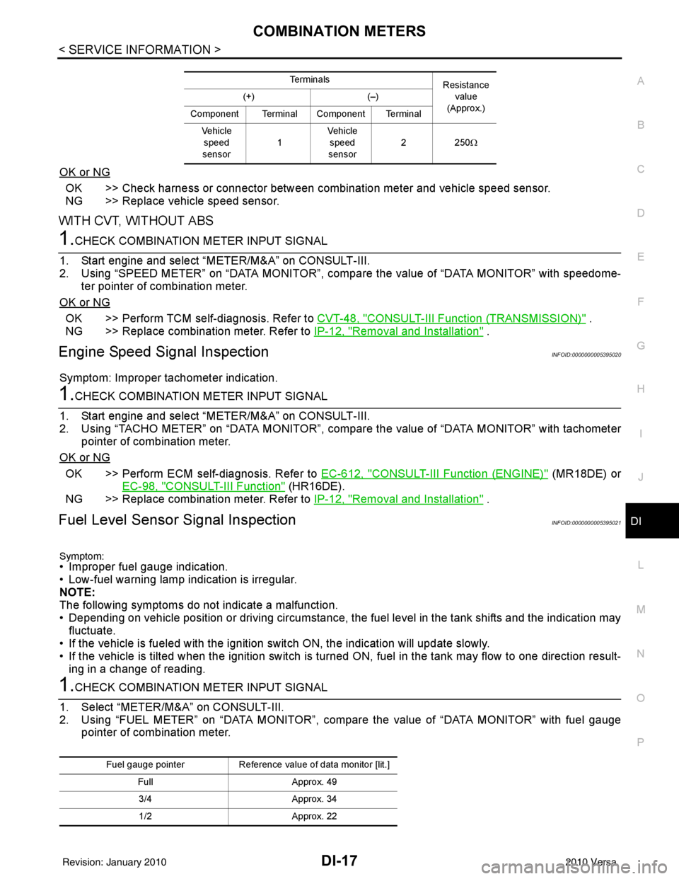
Te r m i n a l s Resistance
value
(Approx.)
(+)
(–)
Component Terminal Component Terminal Ve h i c l e speed
sensor 1Vehicle
speed
sensor 22
50Ω
Fuel gauge pointer Reference value of data monitor [lit.]
Full Approx. 49
3/4 Approx. 34
1/2 Approx. 22
Revision: January 20102010 Versa
Page 1241 of 3745
WARNING LAMPSDI-31
< SERVICE INFORMATION >
C
DE
F
G H
I
J
L
M A
B
DI
N
O P
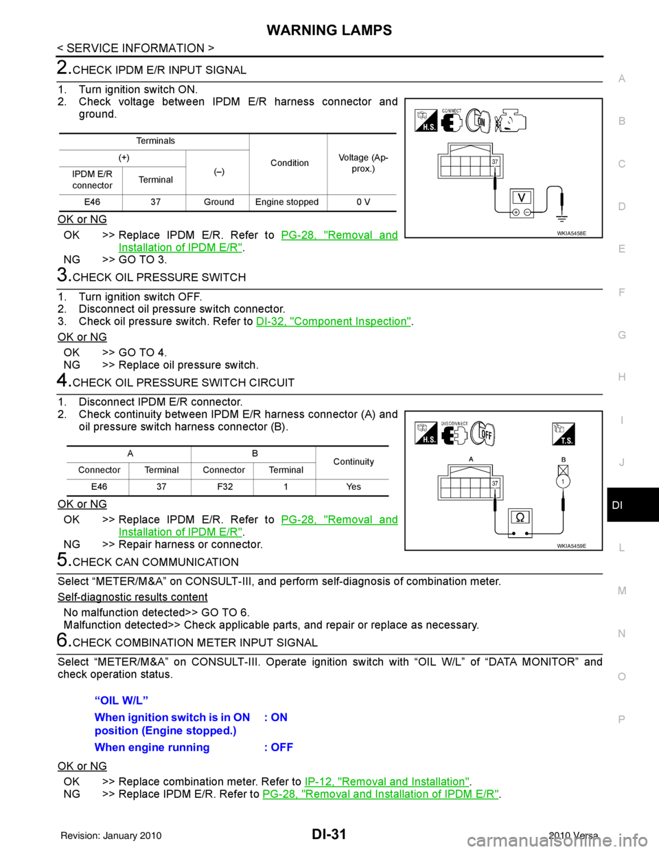
2.CHECK IPDM E/R INPUT SIGNAL
1. Turn ignition switch ON.
2. Check voltage between IPDM E/R harness connector and ground.
OK or NG
OK >> Replace IPDM E/R. Refer to PG-28, "Removal and
Installation of IPDM E/R".
NG >> GO TO 3.
3.CHECK OIL PRESSURE SWITCH
1. Turn ignition switch OFF.
2. Disconnect oil pressure switch connector.
3. Check oil pressure switch. Refer to DI-32, "
Component Inspection".
OK or NG
OK >> GO TO 4.
NG >> Replace oil pressure switch.
4.CHECK OIL PRESSURE SWITCH CIRCUIT
1. Disconnect IPDM E/R connector.
2. Check continuity between IPDM E/R harness connector (A) and oil pressure switch harness connector (B).
OK or NG
OK >> Replace IPDM E/R. Refer to PG-28, "Removal and
Installation of IPDM E/R".
NG >> Repair harness or connector.
5.CHECK CAN COMMUNICATION
Select “METER/M&A” on CONSULT-III, and per form self-diagnosis of combination meter.
Self
-diagnostic results content
No malfunction detected>> GO TO 6.
Malfunction detected>> Check applicable parts, and repair or replace as necessary.
6.CHECK COMBINATION METER INPUT SIGNAL
Select “METER/M&A” on CONS ULT-III. Operate ignition switch with “OIL W/L” of “DATA MONITOR” and
check operation status.
OK or NG
OK >> Replace combination meter. Refer to IP-12, "Removal and Installation".
NG >> Replace IPDM E/R. Refer to PG-28, "
Removal and Installation of IPDM E/R".
Te r m i n a l s
ConditionVoltage (Ap-
prox.)
(+)
(–)
IPDM E/R
connector Te r m i n a l
E46 37 Ground Engine stopped 0 V
WKIA5458E
AB
Continuity
Connector Terminal Connector Terminal
E46 37 F32 1 Yes
WKIA5459E
“OIL W/L”
When ignition switch is in ON
position (Engine stopped.) : ON
When engine running : OFF
Revision: January 20102010 Versa
Page 1243 of 3745
![NISSAN TIIDA 2010 Service Repair Manual WARNING LAMPSDI-33
< SERVICE INFORMATION >
C
DE
F
G H
I
J
L
M A
B
DI
N
O P
Check continuity between oil pressure switch and ground.
Condition Oil pressure [kPa (bar, kg/cm2, psi)]Continuity
Engine sto NISSAN TIIDA 2010 Service Repair Manual WARNING LAMPSDI-33
< SERVICE INFORMATION >
C
DE
F
G H
I
J
L
M A
B
DI
N
O P
Check continuity between oil pressure switch and ground.
Condition Oil pressure [kPa (bar, kg/cm2, psi)]Continuity
Engine sto](/manual-img/5/57397/w960_57397-1242.png)
WARNING LAMPSDI-33
< SERVICE INFORMATION >
C
DE
F
G H
I
J
L
M A
B
DI
N
O P
Check continuity between oil pressure switch and ground.
Condition Oil pressure [kPa (bar, kg/cm2, psi)]Continuity
Engine stopped Less than 29 (0.3, 0.3, 4) Yes
Engine running More than 29 (0.3, 0.3, 4) No
ELF0044D
Revision: January 20102010 Versa
Page 1270 of 3745

EC-5
C
DE
F
G H
I
J
K L
M
EC A
N
O P
Diagnosis Procedure ...........................................
..
343
P0507 ISC SYSTEM .........................................345
Description .......................................................... ..345
DTC Logic .............................................................345
Diagnosis Procedure .............................................345
P0603 ECM POWER SUPPLY .........................347
Description .......................................................... ..347
DTC Logic .............................................................347
Diagnosis Procedure .............................................347
P0605 ECM .......................................................349
Description ............................................................349
DTC Logic .............................................................349
Diagnosis Procedure .............................................350
P0607 ECM .......................................................351
Description ............................................................351
DTC Logic .............................................................351
Diagnosis Procedure .............................................351
P0643 SENSOR POWER SUPPLY .................352
DTC Logic ........................................................... ..352
Wiring Diagram .....................................................353
Diagnosis Procedure .............................................353
P0850 PNP SWITCH ........................................356
Description ............................................................356
DTC Logic .............................................................356
Component Function Check ..................................357
Wiring Diagram .....................................................358
Diagnosis Procedure .............................................358
P1148 CLOSED LOOP CONTROL ..................361
DTC Logic .............................................................361
P1217 ENGINE OVER TEMPERATURE .........362
DTC Logic ........................................................... ..362
Component Function Check ..................................362
Diagnosis Procedure .............................................363
P1225 TP SENSOR ..........................................366
Description .......................................................... ..366
DTC Logic .............................................................366
Diagnosis Procedure .............................................366
Special Repair Requirement .................................367
P1226 TP SENSOR ........................................ ..368
Description .......................................................... ..368
DTC Logic .............................................................368
Diagnosis Procedure .............................................368
Special Repair Requirement .................................369
P1421 COLD START CONTROL ................... ..370
Description .......................................................... ..370
DTC Logic .............................................................370
Diagnosis Procedure .............................................370
P1715 INPUT SPEED SENSOR (PRIMARY
SPEED SENSOR) .......................................... ..
372
Description .......................................................... ..372
DTC Logic ............................................................ ..372
Diagnosis Procedure .............................................372
P1805 BRAKE SWITCH .................................373
Description .............................................................373
DTC Logic ..............................................................373
Wiring Diagram ......................................................374
Diagnosis Procedure .............................................374
Component Inspection (Stop Lamp Switch) ..........376
P2100, P2103 THROTTLE CONTROL MO-
TOR RELAY ....................................................
377
Description .............................................................377
DTC Logic ..............................................................377
Wiring Diagram ......................................................378
Diagnosis Procedure .............................................378
P2101 ELECTRIC THROTTLE CONTROL
FUNCTION ......................................................
381
Description ........................................................... ..381
DTC Logic ..............................................................381
Wiring Diagram ......................................................382
Diagnosis Procedure .............................................382
Component Inspection ...........................................385
Special Repair Requirement ..................................385
P2118 THROTTLE CONTROL MOTOR .........386
Description .............................................................386
DTC Logic ..............................................................386
Wiring Diagram ......................................................387
Diagnosis Procedure .............................................387
Component Inspection ...........................................388
Special Repair Requirement ..................................389
P2119 ELECTRIC THROTTLE CONTROL
ACTUATOR .....................................................
390
Description .............................................................390
DTC Logic ..............................................................390
Diagnosis Procedure .............................................390
Special Repair Requirement ..................................391
P2122, P2123 APP SENSOR .........................392
Description .............................................................392
DTC Logic ..............................................................392
Wiring Diagram ......................................................393
Diagnosis Procedure .............................................393
Component Inspection ...........................................395
Special Repair Requirement ..................................395
P2127, P2128 APP SENSOR .........................396
Description .............................................................396
DTC Logic ..............................................................396
Wiring Diagram ......................................................397
Diagnosis Procedure .............................................397
Component Inspection ...........................................399
Special Repair Requirement ..................................400
P2135 TP SENSOR .........................................401
Description .............................................................401
DTC Logic ..............................................................401
Revision: January 20102010 Versa
Page 1271 of 3745

EC-6
Wiring Diagram ......................................................402
Diagnosis Procedure .............................................402
Component Inspection ...........................................404
Special Repair Requirement ..................................404
P2138 APP SENSOR ..................................... .405
Description ........................................................... ..405
DTC Logic ..............................................................405
Wiring Diagram ......................................................406
Diagnosis Procedure .............................................406
Component Inspection ...........................................409
Special Repair Requirement ..................................409
P2A00 A/F SENSOR 1 ................................... .410
Description ........................................................... ..410
DTC Logic ..............................................................410
Wiring Diagram ......................................................411
Diagnosis Procedure .............................................412
COOLING FAN ................................................415
Description ........................................................... ..415
Component Function Check ..................................415
Wiring Diagram ......................................................416
Diagnosis Procedure .............................................417
Component Inspection ...........................................419
ELECTRICAL LOAD SIGNAL .........................421
Description ........................................................... ..421
Component Function Check ..................................421
Diagnosis Procedure .............................................421
FUEL INJECTOR .............................................423
Description ........................................................... ..423
Component Function Check ..................................423
Wiring Diagram ......................................................424
Diagnosis Procedure .............................................424
Component Inspection ...........................................425
FUEL PUMP .....................................................427
Description ........................................................... ..427
Component Function Check ..................................427
Wiring Diagram ......................................................428
Diagnosis Procedure .............................................428
Component Inspection ...........................................430
IGNITION SIGNAL ...........................................432
Description ........................................................... ..432
Component Function Check ..................................432
Wiring Diagram ......................................................433
Diagnosis Procedure .............................................434
Component Inspection (Ignition Coil with Power
Transistor) .............................................................
437
Component Inspection (Condenser-2) ..................438
MALFUNCTION INDICATOR LAMP ...............439
Description ........................................................... ..439
Component Function Check ..................................439
Wiring Diagram ......................................................440
Diagnosis Procedure .............................................441
ON BOARD REFUELING VAPOR RECOV-
ERY (ORVR) .....................................................
443
Description ........................................................... .443
Component Function Check .................................443
Diagnosis Procedure .............................................443
Component Inspection (Refueling EVAP vapor cut
valve) ................................................................... .
446
Component Inspection (Drain filter) ......................448
POSITIVE CRANKCASE VENTILATION .........449
Description ........................................................... .449
Component Inspection ..........................................449
REFRIGERANT PRESSURE SENSOR ...........450
Description ........................................................... .450
Component Function Check .................................450
Wiring Diagram .....................................................451
Diagnosis Procedure .............................................451
ECU DIAGNOSIS ......................................454
ECM ................................................................ ..454
Reference Value .................................................. .454
Wiring Diagram — ENGINE CONTROL SYSTEM
— ..........................................................................
464
Fail Safe ...............................................................465
DTC Inspection Priority Chart .............................467
DTC Index ............................................................468
How to Set SRT Code .......................................471
How to Erase Permanent DTC .............................473
Test Value and Test Limit .....................................477
SYMPTOM DIAGNOSIS ...........................484
ENGINE CONTROL SYSTEM SYMPTOMS .. ..484
Symptom Table .................................................... .484
NORMAL OPERATING CONDITION ...............488
Description ........................................................... .488
PRECAUTION ...........................................489
PRECAUTIONS .............................................. ..489
Precaution for Supplemental Restraint System
(SRS) "AIR BAG" and "SEAT BELT PRE-TEN-
SIONER" .............................................................. .
489
Precaution Necessary for Steering Wheel Rota-
tion After Battery Disconnect ................................
489
Precaution for Procedure without Cowl Top Cover .490
On Board Diagnosis (OBD) System of Engine and
A/T ........................................................................
490
General Precautions .............................................490
PREPARATION .........................................494
PREPARATION .............................................. ..494
Special Service Tools .......................................... .494
Commercial Service Tools ....................................494
ON-VEHICLE MAINTENANCE .................496
Revision: January 20102010 Versa