2010 NISSAN TIIDA spare wheel
[x] Cancel search: spare wheelPage 3179 of 3745

MA-44
< SERVICE INFORMATION >
CHASSIS AND BODY MAINTENANCE
5. Run engine at idle speed for 5 minutes.
6. Check A/T fluid level and condition. Refer to MA-43, "
A/T FLUID : Checking A/T Fluid".
WHEELS
WHEELS : Balancing WheelsINFOID:0000000005714347
Adjust wheel balance using road wheel center.
CAUTION:
• Be careful not to scratch the road wheel during removal.
• Use clip-on type wheel balance weights only.
Wheel balance (Maximum allowable unbalance):
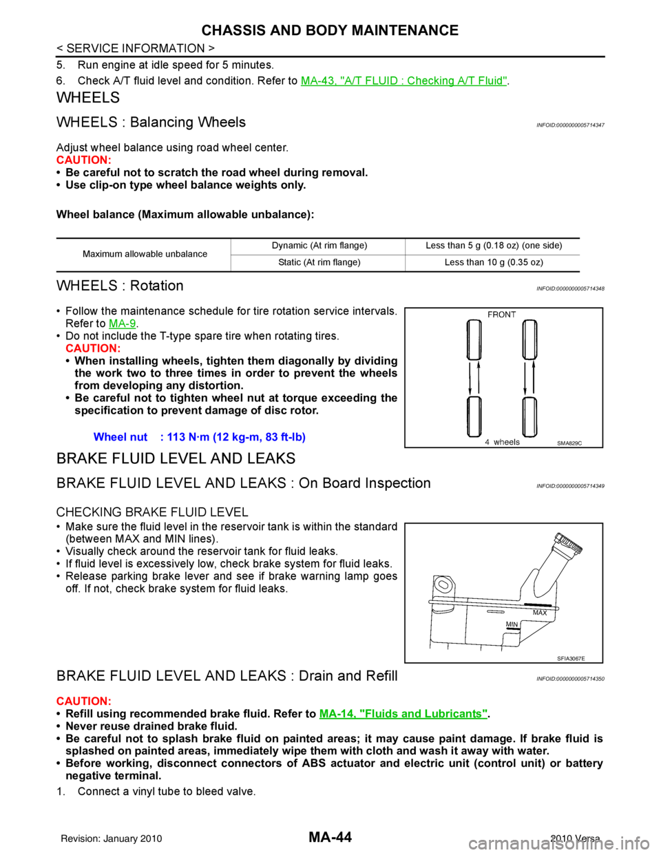
WHEELS : RotationINFOID:0000000005714348
• Follow the maintenance schedule for tire rotation service intervals.
Refer to MA-9
.
• Do not include the T-type spare tire when rotating tires.
CAUTION:
• When installing wheels, tighten them diagonally by dividing
the work two to three times in order to prevent the wheels
from developing any distortion.
• Be careful not to tighten wheel nut at torque exceeding the specification to prevent damage of disc rotor.
BRAKE FLUID LEVEL AND LEAKS
BRAKE FLUID LEVEL AND LEAK S : On Board InspectionINFOID:0000000005714349
CHECKING BRAKE FLUID LEVEL
• Make sure the fluid level in the reservoir tank is within the standard
(between MAX and MIN lines).
• Visually check around the reservoir tank for fluid leaks.
• If fluid level is excessively low, check brake system for fluid leaks.
• Release parking brake lever and see if brake warning lamp goes off. If not, check brake system for fluid leaks.
BRAKE FLUID LEVEL AND LE AKS : Drain and RefillINFOID:0000000005714350
CAUTION:
• Refill using recommended brake fluid. Refer to MA-14, "
Fluids and Lubricants".
• Never reuse drained brake fluid.
• Be careful not to splash brake fluid on painted areas; it may cause paint damage. If brake fluid is
splashed on painted areas, immediately wipe them with cloth and wash it away with water.
• Before working, disconnect connectors of ABS actua tor and electric unit (control unit) or battery
negative terminal.
1. Connect a vinyl tube to bleed valve.
Maximum allowable unbalance Dynamic (At rim flange) Less than 5 g (0.18 oz) (one side)
Static (At rim flange) Less than 10 g (0.35 oz)
Wheel nut : 113 N·m (12 kg-m, 83 ft-lb)SMA829C
SFIA3067E
Revision: January 20102010 Versa
Page 3517 of 3745

PRECAUTIONSRSU-3
< SERVICE INFORMATION >
C
DF
G H
I
J
K L
M A
B
RSU
N
O P
5. When the repair work is completed, return the ignition switch to the ″LOCK ″ position before connecting
the battery cables. (At this time, the steering lock mechanism will engage.)
6. Perform a self-diagnosis check of al l control units using CONSULT-III.
Precaution for Rear SuspensionINFOID:0000000005397074
• When installing the rubber bushings, the final tightening must be done under unladen condition and with the
tires on level ground. Oil will shorten the life of the rubber bushings, so wipe off any spilled oil immediately.
• Unladen condition means the fuel tank, engine coolant and lubricants are at the full specification. The spare
tire, jack, hand tools, and mats are in their designated positions.
• After installing suspension components, check the wheel alignment.
• Caulking nuts are not reusable. Always use new caulking nuts for installation. New caulking nuts are pre- oiled, do not apply any additional lubrication.
Revision: January 20102010 Versa
Page 3520 of 3745

RSU-6
< SERVICE INFORMATION >
REAR SUSPENSION ASSEMBLY
REAR SUSPENSION ASSEMBLY
On-Vehicle Inspection and ServiceINFOID:0000000005397077
Make sure the mounting conditions (looseness, backlash) of each component and component conditions
(wear, damage) are within specifications.
SHOCK ABSORBER INSPECTION
Check shock absorber for oil leakage, damage and replace it if necessary.
Wheel AlignmentInspectionINFOID:0000000005397078
DESCRIPTION
Measure wheel alignment under unladen conditions.
NOTE:
“Unladen conditions” means that fuel, engine coolant, and lubricant are full. Spare tire, jack, hand tools and
mats are in designated positions.
PRELIMINARY
Check the following:
1. Tires for improper air pressure and wear.
2. Road wheels for runout. Refer to WT-6
.
3. Wheel bearing axial end play. Refer to RAX-6, "
On-Vehicle Inspection and Service" .
4. Shock absorber operation.
5. Each mounting part of suspension for looseness and deformation.
6. Rear suspension beam for cracks, deformation, and other damage.
7. Vehicle height (posture).
GENERAL INFORMATION AND RECOMMENDATIONS
1. A Four-Wheel Thrust Alignment should be performed. • This type of alignment is recommended for any NISSAN vehicle.
• The four-wheel “thrust” process helps ensure that the vehicle is properly aligned and the steering wheel
is centered.
• The alignment machine itself should be ca pable of accepting any NISSAN vehicle.
• The alignment machine should be checked to ensure that it is level.
2. Make sure the alignment machine is properly calibrated. • Your alignment machine should be regularly calibrated in order to give correct information.
• Check with the manufacturer of your specific al ignment machine for their recommended Service/Cali-
bration Schedule.
THE ALIGNMENT PROCESS
IMPORTANT: Use only the alignment specifications listed in this Service Manual. Refer to RSU-13, "Wheel
Alignment (Unladen*)" .
1. When displaying the alignment settings, many alignment machines use “indicators”: (Green/red, plus or minus, Go/No Go). Do NOT use these indicators.
• The alignment specifications programmed into your alignment machine that operate these indicators may not be correct.
• This may result in an ERROR.
2. Some newer alignment machines are equipped with an optional “Rolling Compensation” method to “com- pensate” the sensors (alignment targets or head units). Do NOT use this “Rolling Compensation”
method.
• Use the “Jacking Compensation” method. After inst alling the alignment targets or head units, raise the
vehicle and rotate the wheels 1/2 turn both ways.
• See Instructions in the alignment machine you are using for more information.
CAMBER INSPECTION
Revision: January 20102010 Versa
Page 3527 of 3745

SERVICE DATA AND SPECIFICATIONS (SDS)RSU-13
< SERVICE INFORMATION >
C
DF
G H
I
J
K L
M A
B
RSU
N
O P
SERVICE DATA AND SPECIFICATIONS (SDS)
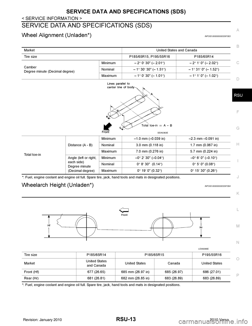
Wheel Alignment (Unladen*)INFOID:0000000005397083
*: Fuel, engine coolant and engine oil full. Spare tire, jack, hand tools and mats in designated positions.
Wheelarch Height (Unladen*)INFOID:0000000005397084
*: Fuel, engine coolant and engine oil full. Spare tire, jack, hand tools and mats in designated positions. Market
United States and Canada
Tire size P185/65R15, P195/55R16 P185/65R14
Camber
Degree minute (Decimal degree) Minimum
– 2° 0′ 30" (– 2.01 °)– 2° 1 ′ 0" (– 2.02 °)
Nominal – 1° 30 ′ 30" (– 1.51 °)– 1° 31 ′ 0" (– 1.52 °)
Maximum – 1° 0′ 30" (– 1.01 °)– 1° 1 ′ 0" (– 1.02 °)
To t a l t o e - i n Distance (A - B)
Minimum
–1.0 mm (–0.039 in) –2.3 mm –0.091 in)
Nominal 3.0 mm (0.118 in) 1.7 mm (0.067 in)
Maximum 7.0 mm (0.276 in) 5.7 mm (0.224 in)
Angle (left or right,
each side)
Degree minute
(Decimal degree) Minimum
–0° 2 ′ 30" (–0.04 °)– 0° 6 ′ 0" (–0.10 °)
Nominal 0° 8 ′ 30" (0.14 °)0 ° 5 ′ 0" (0.08 °)
Maximum 0° 19 ′ 0" (0.32 °)0 ° 15 ′ 30" (0.26 °)
SEIA0363E
Tire size P185/65R14P185/65R15P195/55R16
Market United States
and Canada United States
CanadaUnited States
Front (Hf) 677 (26.65) 685 mm (26.97 in) 685 (26.97) 686 (27.01)
Rear (Hr) 681 (26.81) 682 mm (26.85 in) 683 (26.89) 683 (26.89)
LEIA0085E
Revision: January 20102010 Versa
Page 3685 of 3745

WT-8
< SERVICE INFORMATION >
ROAD WHEEL TIRE ASSEMBLY
4. If calculated balance weight value exceeds 50 g (1.76 oz), installtwo balance weight sheets in line with each other as shown.
CAUTION:
Do not install one balance weight sheet on top another.
5. Start balancer machine again.
6. Install balance weight on inner side of road wheel in the bal- ancer machine indication position (angle).
CAUTION:
Do not install more than two balance weights.
7. Start balancer machine. Make sure that inner and outer residual imbalance values are 5 g (0.17 oz) each or below.
8. If either residual imbalance value exceeds 5 g (0.17 oz), repeat installation procedures.
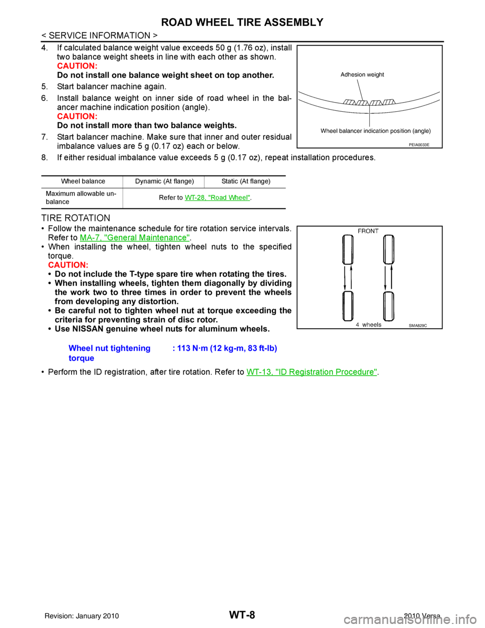
TIRE ROTATION
• Follow the maintenance schedule for tire rotation service intervals.
Refer to MA-7, "
General Maintenance".
• When installing the wheel, tighten wheel nuts to the specified
torque.
CAUTION:
• Do not include the T-type spare tire when rotating the tires.
• When installing wheels, tighten them diagonally by dividing
the work two to three times in order to prevent the wheels
from developing any distortion.
• Be careful not to tighten wheel nut at torque exceeding the criteria for preventing strain of disc rotor.
• Use NISSAN genuine wheel nuts for aluminum wheels.
• Perform the ID registration, after tire rotation. Refer to WT-13, "
ID Registration Procedure".
Wheel balance Dynamic (At flange) Static (At flange)
Maximum allowable un-
balance Refer to
WT-28, "
Road Wheel".
PEIA0033E
Wheel nut tightening
torque : 113 N·m (12 kg-m, 83 ft-lb)
SMA829C
Revision: January 20102010 Versa
Page 3705 of 3745

WT-28
< SERVICE INFORMATION >
SERVICE DATA AND SPECIFICATIONS (SDS)
SERVICE DATA AND SPECIFICATIONS (SDS)
Road WheelINFOID:0000000005397116
TireINFOID:0000000005397117
Unit: kPa (kg/cm2 , psi)
Standard itemAllowable
Aluminum Steel
Maximum radial runout limit Lateral deflection
Less than 0.3 mm (0.012 in) Less than 0.5 mm (0.020 in)
Radial deflection Less than 0.3 mm (0.012 in) Less than 0.8 mm (0.031 in)
Maximum allowable imbalance Dynamic
(At rim flange)
Less than 5 g (0.18 oz) (one side)
Stati c
(At rim flange) Less than 10 g (0.35 oz)
Tire size Cold tire pressure
Conventional tire Spare ti re
Front wheel Rear wheel
P185/65R14 230 (2.3, 33) 230 (2.3, 33)—
P185/65R15 230 (2.3, 33) 230 (2.3, 33)—
P195/55R16 240 (2.4, 35) 240 (2.4, 35)—
T125/70D15 ——420 (4.2, 60)
Revision: January 20102010 Versa