2010 NISSAN TIIDA mirror
[x] Cancel search: mirrorPage 2718 of 3745

GW-1
BODY
C
DE
F
G H
J
K L
M
SECTION GW
A
B
GW
N
O P
CONTENTS
GLASSES, WINDOW SYSTEM & MIRRORS
SERVICE INFORMATION .. ..........................3
PRECAUTIONS .............................................. .....3
Precaution for Supplemental Restraint System
(SRS) "AIR BAG" and "SEAT BELT PRE-TEN-
SIONER" ............................................................. ......
3
Precaution Necessary for Steering Wheel Rota-
tion After Battery Disconnect ............................... ......
3
Precaution for Procedure without Cowl Top Cover ......4
Handling for Adhesive and Primer ............................4
PREPARATION ...................................................5
Commercial Service Tool .................................... ......5
SQUEAK AND RATTLE TROUBLE DIAG-
NOSES ................................................................
6
Work Flow ........................................................... ......6
Generic Squeak and Rattle Troubleshooting ............8
Diagnostic Worksheet .............................................10
WINDSHIELD GLASS ........................................12
Removal and Installation .........................................12
OPERA WINDOW GLASS .................................14
Removal and Installation .........................................14
REAR WINDOW GLASS AND MOLDING ..... ....16
Removal and Installation .........................................16
POWER WINDOW SYSTEM ..............................19
Component Parts and Harness Connector Loca-
tion ...................................................................... ....
19
System Description .................................................19
CAN Communication System Description ...............23
Schematic ...............................................................24
Wiring Diagram - WINDOW- ...................................25
Main Power Window and Door Lock/Unlock
Switch Harness Connector Terminal Layout ...........
29
Terminal and Reference Value for Main Power
Window and Door Lock/Unlock Switch ...................
29
Terminal and Reference Value for BCM .................30
Work Flow ...............................................................30
CONSULT-III Function (BCM) .................................30
Trouble Diagnosis Symptom Chart ...................... ....31
BCM Power Supply and Ground Circuit Inspection
....
32
Main Power Window and Door Lock/Unlock
Switch Power Supply and Ground Circuit Inspec-
tion ....................................................................... ....
32
Front Power Window Motor LH Circuit Inspection ....33
Front Power Window RH Circuit Inspection (Pow-
er Window and Door Lock/Unlock Switch RH Op-
eration) ....................................................................
34
Front Power Window Motor RH Circuit Inspection ....34
Encoder Circuit Inspection .......................................36
Door Switch Check ..................................................38
Rear Power Window LH Circuit Inspection (Rear
Power Window Switch LH Operation) .....................
39
Rear Power Window RH Circuit Inspection (Rear
Power Window Switch RH Operation) ................. ....
40
Rear Power Window Motor LH Circuit Inspection ....40
Rear Power Window Motor RH Circuit Inspection ....42
FRONT DOOR GLASS AND REGULATOR .....44
Removal and Installation .........................................44
Disassembly and Assembly .....................................46
Inspection after Installation ......................................46
REAR DOOR GLASS AND REGULATOR .......48
Removal and Installation ..................................... ....48
Disassembly and Assembly .....................................50
Inspection after Installation ......................................50
REAR WINDOW DEFOGGER ..........................51
Component Parts and Harness Connector Loca-
tion ....................................................................... ....
51
System Description ..................................................51
CAN Communication System Description ...............52
Wiring Diagram - DEF - ...........................................53
Terminal and Reference Value for BCM ..................55
Terminal and Reference Value for IPDM E/R ...... ....55
Work Flow ................................................................55
CONSULT-III Function (BCM) .................................55
Revision: January 20102010 Versa
Page 2719 of 3745

GW-2
Trouble Diagnosis Symptom Chart .........................55
BCM Power Supply and Ground Circuit Inspection
...
56
Rear Window Defogger Switch Circuit Inspection ...56
Rear Window Defogger Circ uit Inspection ..............57
Door Mirror Defogger Circu it Inspection .................60
Filament Check .................................................... ...61
Filament Repair ......................................................62
DOOR MIRROR .................................................64
Wiring Diagram - MIRROR - ................................ ...64
Removal and Installation .........................................65
Disassembly and Assembly ................................. ...65
INSIDE MIRROR ................................................67
Removal and Installation .........................................67
Revision: January 20102010 Versa
Page 2729 of 3745
GW-12
< SERVICE INFORMATION >
WINDSHIELD GLASS
WINDSHIELD GLASS
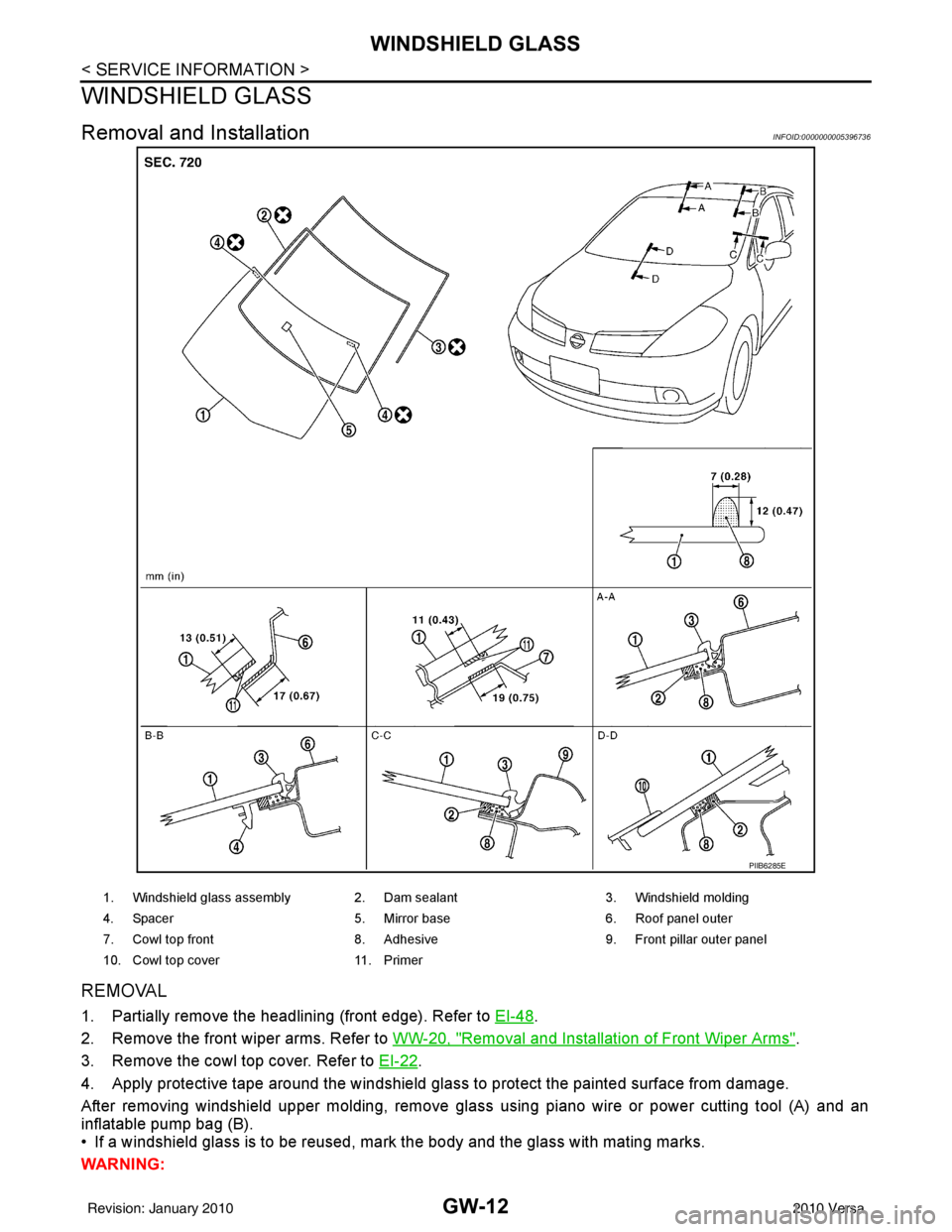
Removal and InstallationINFOID:0000000005396736
REMOVAL
1. Partially remove the headlining (front edge). Refer to EI-48.
2. Remove the front wiper arms. Refer to WW-20, "
Removal and Installation of Front Wiper Arms".
3. Remove the cowl top cover. Refer to EI-22
.
4. Apply protective tape around the windshield glas s to protect the painted surface from damage.
After removing windshield upper molding, remove glass using piano wire or power cutting tool (A) and an
inflatable pump bag (B).
• If a windshield glass is to be reused, mark the body and the glass with mating marks.
WARNING:
PIIB6285E
1. Windshield glass assembly 2. Dam sealant 3. Windshield molding
4. Spacer 5. Mirror base 6. Roof panel outer
7. Cowl top front 8. Adhesive 9. Front pillar outer panel
10. Cowl top cover 11. Primer
Revision: January 20102010 Versa
Page 2768 of 3745
REAR WINDOW DEFOGGERGW-51
< SERVICE INFORMATION >
C
DE
F
G H
J
K L
M A
B
GW
N
O P
REAR WINDOW DEFOGGER
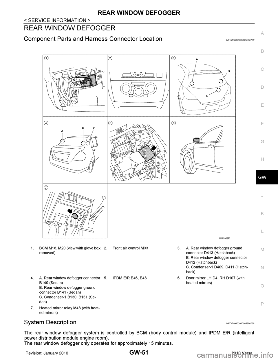
Component Parts and Har ness Connector LocationINFOID:0000000005396768
System DescriptionINFOID:0000000005396769
The rear window defogger system is controlled by BCM (body control module) and IPDM E/R (intelligent
power distribution module engine room).
The rear window defogger only operates for approximately 15 minutes.
1. BCM M18, M20 (view with glove box
removed) 2. Front air control M33 3. A. Rear window defogger ground
connector D413 (Hatchback)
B. Rear window defogger connector
D412 (Hatchback)
C. Condenser-1 D409, D411 (Hatch-
back)
4. A. Rear window defogger connector B140 (Sedan)
B. Rear window defogger ground
connector B141 (Sedan)
C. Condenser-1 B130, B131 (Se-
dan) 5. IPDM E/R E46, E48
6. Door mirror LH D4, RH D107 (with
heated mirrors)
7. Heated mirror relay M48 (with heat- ed mirrors)
LIIA2929E
Revision: January 20102010 Versa
Page 2769 of 3745

GW-52
< SERVICE INFORMATION >
REAR WINDOW DEFOGGER
Power is supplied at all times
• through 15A fuses (No. 46 and 47, located in the IPDM E/R)
• to rear window defogger relay
• through 10A fuse [No. 5 (with heated mirrors), located in the fuse block (J/B)]
• to heated mirror relay terminal 3
• through 40A fusible link (letter g , located in the fuse and fusible link box)
• to BCM terminal 70.
With the ignition switch turned to ON or START position, power is supplied
• through ignition relay
• to rear window defogger relay (located in the IPDM E/R)
• through 10A fuse [No. 6, located in the fuse block (J/B)]
• to BCM terminal 38.
Ground is supplied
• to BCM terminal 67 and
• to front air control terminal 8
• through body grounds M57 and M61
• to IPDM E/R terminals 39 and 59
• through body grounds E15 and E24.
When front air control (rear window defogger switch) is turned to ON, ground is supplied
• to BCM terminal 9
• through front air control terminal 3
• through front air control terminal 8
• through body grounds M57 and M61.
Then rear window defogger switch is illuminated.
Then BCM recognizes that rear window defogger switch is turned to ON.
Then it sends rear window defogger switch signals to IPDM E/R via CAN communication (CAN-H, CAN-L).
When IPDM E/R receives rear window defogger switch signals, ground is supplied
• to rear window defogger relay (located in the IPDM E/R)
• through IPDM E/R terminals 39 and 59
• through body grounds E15 and E24
Then rear window defogger relay is energized.
With power and ground supplied, rear window def ogger filaments heat and defog the rear window.
When rear window defogger relay is turned to ON (with heated mirrors), power is supplied
• through heated mirror relay terminal 5
• to door mirror (LH and RH) terminal 1.
Door mirror (LH and RH) is grounded through body grounds M57 and M61.
With power and ground supplied, rear window defogger filaments heat and defog the rear window and door
mirror filaments heat and defog the mirrors.
CAN Communication System DescriptionINFOID:0000000005396770
Refer to LAN-7, "System Description".
Revision: January 20102010 Versa
Page 2773 of 3745
GW-56
< SERVICE INFORMATION >
REAR WINDOW DEFOGGER
BCM Power Supply and Ground Circuit Inspection
INFOID:0000000005396777
Refer to BCS-16, "BCM Power Supply and Ground Circuit Inspection" .
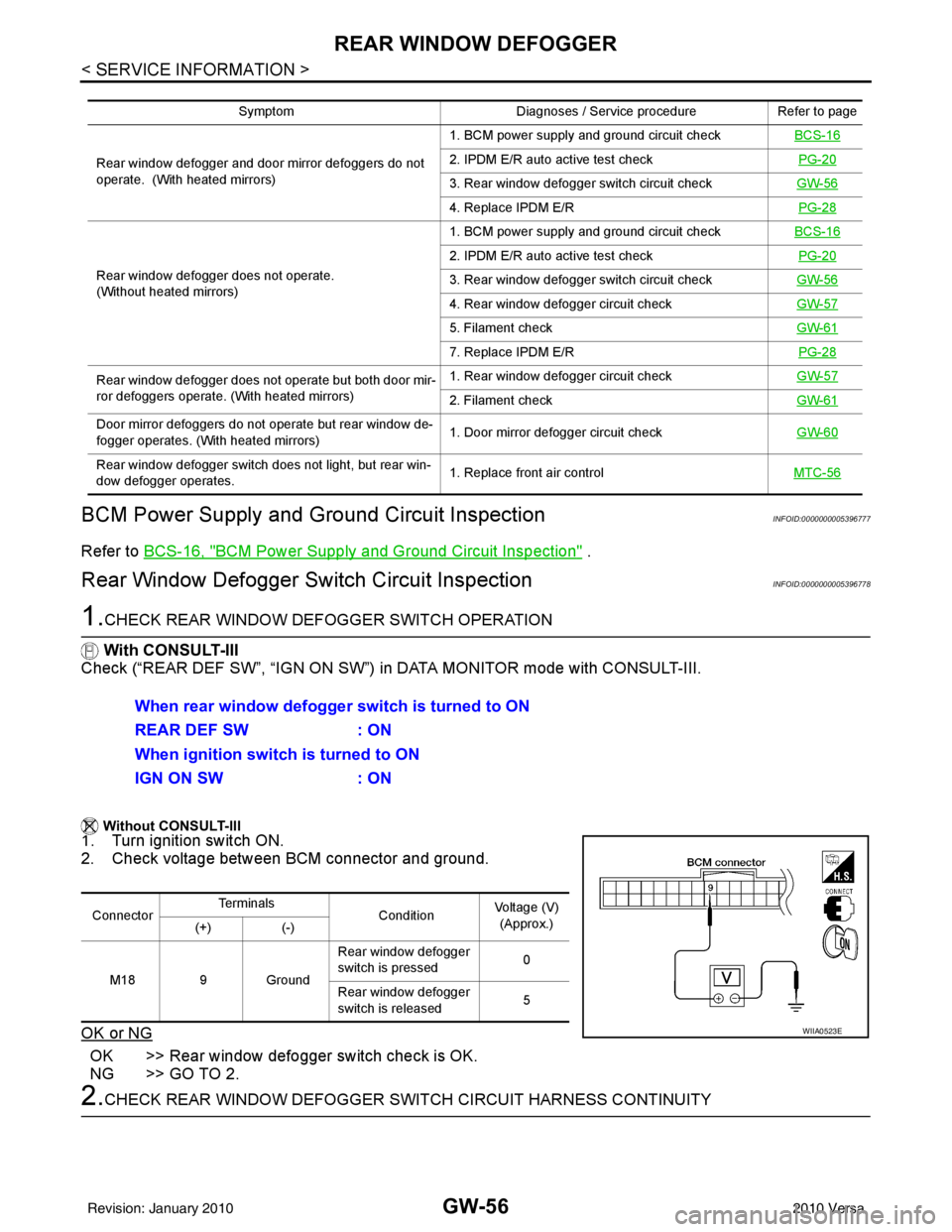
Rear Window Defogger Swit ch Circuit InspectionINFOID:0000000005396778
1.CHECK REAR WINDOW DEFOGGER SWITCH OPERATION
With CONSULT-III
Check (“REAR DEF SW”, “IGN ON SW”) in DATA MONITOR mode with CONSULT-III.
Without CONSULT-III
1. Turn ignition switch ON.
2. Check voltage between BCM connector and ground.
OK or NG
OK >> Rear window defogger switch check is OK.
NG >> GO TO 2.
2.CHECK REAR WINDOW DEFOGGER SWITCH CIRCUIT HARNESS CONTINUITY
Symptom Diagnoses / Service procedureRefer to page
Rear window defogger and door mirror defoggers do not
operate. (With heated mirrors) 1. BCM power supply and ground circuit check
BCS-16
2. IPDM E/R auto active test check PG-20
3. Rear window defogger switch circuit checkGW-56
4. Replace IPDM E/R PG-28
Rear window defogger does not operate.
(Without heated mirrors) 1. BCM power supply and ground circuit check
BCS-16
2. IPDM E/R auto active test check PG-20
3. Rear window defogger switch circuit checkGW-56
4. Rear window defogger circuit checkGW-57
5. Filament checkGW-61
7. Replace IPDM E/R PG-28
Rear window defogger does not operate but both door mir-
ror defoggers operate. (With heated mirrors) 1. Rear window defogger circuit check
GW-57
2. Filament checkGW-61
Door mirror defoggers do not operate but rear window de-
fogger operates. (With heated mirrors) 1. Door mirror defogger circuit check
GW-60
Rear window defogger switch does not light, but rear win-
dow defogger operates. 1. Replace front air control
MTC-56
When rear window defogger switch is turned to ON
REAR DEF SW: ON
When ignition switch is turned to ON
IGN ON SW : ON
ConnectorTe r m i n a l s
ConditionVoltage (V)
(Approx.)
(+) (-)
M18 9 Ground Rear window defogger
switch is pressed
0
Rear window defogger
switch is released 5
WIIA0523E
Revision: January 20102010 Versa
Page 2777 of 3745
GW-60
< SERVICE INFORMATION >
REAR WINDOW DEFOGGER
OK or NG
OK >> Check condition of harness and connector.
NG >> Replace IPDM E/R. Refer to PG-28, "
Removal and Installation of IPDM E/R" .
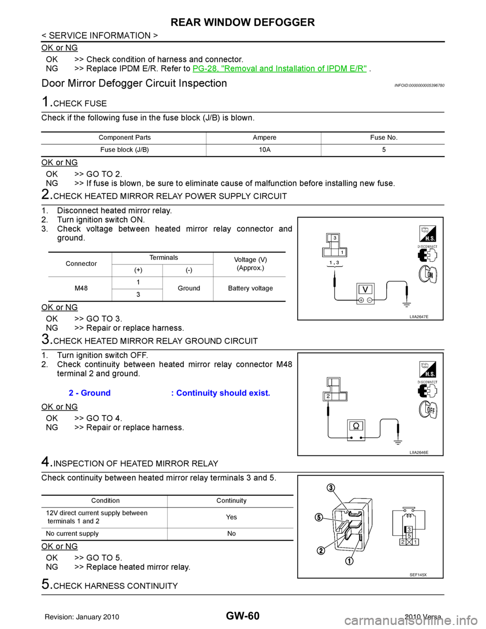
Door Mirror Defogger Circuit InspectionINFOID:0000000005396780
1.CHECK FUSE
Check if the following fuse in the fuse block (J/B) is blown.
OK or NG
OK >> GO TO 2.
NG >> If fuse is blown, be sure to eliminate cause of malfunction before installing new fuse.
2.CHECK HEATED MIRROR RELAY POWER SUPPLY CIRCUIT
1. Disconnect heated mirror relay.
2. Turn ignition switch ON.
3. Check voltage between heated mirror relay connector and ground.
OK or NG
OK >> GO TO 3.
NG >> Repair or replace harness.
3.CHECK HEATED MIRROR RELAY GROUND CIRCUIT
1. Turn ignition switch OFF.
2. Check continuity between heated mirror relay connector M48 terminal 2 and ground.
OK or NG
OK >> GO TO 4.
NG >> Repair or replace harness.
4.INSPECTION OF HEATED MIRROR RELAY
Check continuity between heated mirror relay terminals 3 and 5.
OK or NG
OK >> GO TO 5.
NG >> Replace heated mirror relay.
5.CHECK HARNESS CONTINUITY
Component Parts AmpereFuse No.
Fuse block (J/B) 10A5
ConnectorTe r m i n a l s
Voltage (V)
(Approx.)
(+) (-)
M48 1
Ground Battery voltage
3
LIIA2647E
2 - Ground : Continuity should exist.
LIIA2646E
Condition Continuity
12V direct current supply between
terminals 1 and 2 Ye s
No current supply No
SEF145X
Revision: January 20102010 Versa
Page 2778 of 3745
REAR WINDOW DEFOGGERGW-61
< SERVICE INFORMATION >
C
DE
F
G H
J
K L
M A
B
GW
N
O P
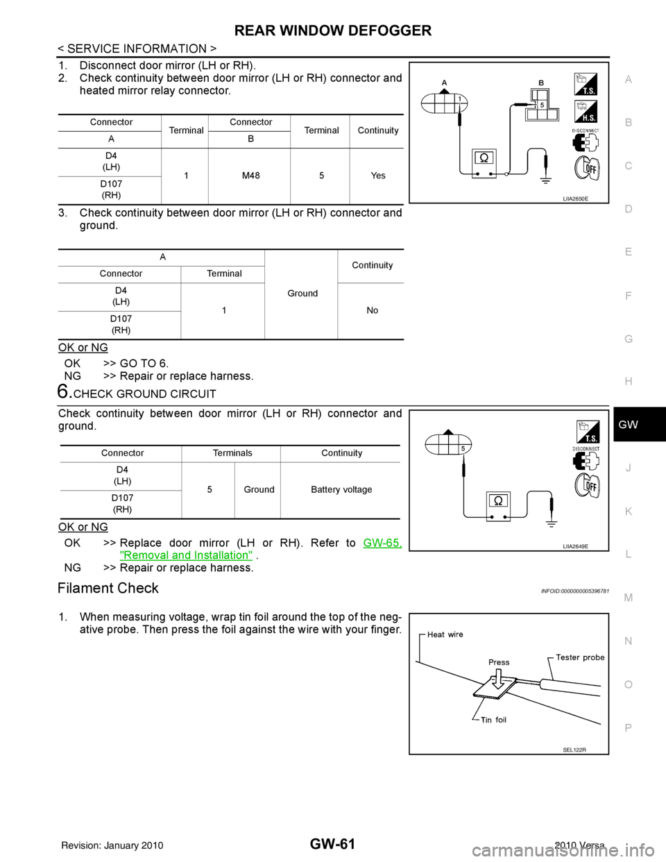
1. Disconnect door mirror (LH or RH).
2. Check continuity between door mirror (LH or RH) connector and heated mirror relay connector.
3. Check continuity between door mirror (LH or RH) connector and ground.
OK or NG
OK >> GO TO 6.
NG >> Repair or replace harness.
6.CHECK GROUND CIRCUIT
Check continuity between door mirror (LH or RH) connector and
ground.
OK or NG
OK >> Replace door mirror (LH or RH). Refer to GW-65,
"Removal and Installation" .
NG >> Repair or replace harness.
Filament CheckINFOID:0000000005396781
1. When measuring voltage, wrap tin foil around the top of the neg- ative probe. Then press the foil against the wire with your finger.
Connector Te r m i n a lConnector
Terminal Continuity
AB
D4
(LH) 1M48 5Yes
D107
(RH)
A GroundContinuity
Connector Terminal
D4
(LH) 1N o
D107
(RH)
LIIA2650E
Connector TerminalsContinuity
D4
(LH) 5 Ground Battery voltage
D107
(RH)
LIIA2649E
SEL122R
Revision: January 20102010 Versa