2010 NISSAN TIIDA fuel tank removal
[x] Cancel search: fuel tank removalPage 2042 of 3745
![NISSAN TIIDA 2010 Service Repair Manual DTC P0182, P0183 FTT SENSOREC-777
< SERVICE INFORMATION > [MR18DE]
C
D
E
F
G H
I
J
K L
M A
EC
NP
O
3. Check harness continuity between “fuel level sensor unit and fuel pump” terminal 5 and combina NISSAN TIIDA 2010 Service Repair Manual DTC P0182, P0183 FTT SENSOREC-777
< SERVICE INFORMATION > [MR18DE]
C
D
E
F
G H
I
J
K L
M A
EC
NP
O
3. Check harness continuity between “fuel level sensor unit and fuel pump” terminal 5 and combina](/manual-img/5/57397/w960_57397-2041.png)
DTC P0182, P0183 FTT SENSOREC-777
< SERVICE INFORMATION > [MR18DE]
C
D
E
F
G H
I
J
K L
M A
EC
NP
O
3. Check harness continuity between “fuel level sensor unit and fuel pump” terminal 5 and combination
meter terminal 24. Refer to Wiring Diagram.
4. Also check harness for short to ground and short to power.
OK or NG
OK >> GO TO 6.
NG >> GO TO 5.
5.DETECT MALFUNCTIONING PART
Check the following.
• Harness connectors B102, M13
• Harness for open or short between “fuel level sensor unit and fuel pump” and ground.
>> Repair open circuit or short to ground or short to power in harness or connectors.
6.CHECK FUEL TANK TEMPERATURE SENSOR
Refer to, EC-777, "
Component Inspection".
OK or NG
OK >> GO TO 7.
NG >> Replace “fuel level sensor unit and fuel pump”.
7.CHECK INTERMITTENT INCIDENT
Perform EC-632
.
>> INSPECTION END
Component InspectionINFOID:0000000005532617
FUEL TANK TEMPERATURE SENSOR
1. Check resistance between “fuel level sensor unit and fuel pump”
terminal 4 and 5 by heating with hot water as shown in the fig-
ure.
2. If NG, replace “fuel level sensor unit and fuel pump”.
Removal and InstallationINFOID:0000000005532618
FUEL TANK TEMPERATURE SENSOR
Refer to FL-6, "Removal and Installation".
Continuity should exist.
Temperature [
°C ( °F)] Resistance (k Ω)
20 (68) 2.3 - 2.7
50 (122) 0.79 - 0.90
PBIB0931E
Revision: January 20102010 Versa
Page 2133 of 3745
![NISSAN TIIDA 2010 Service Repair Manual EC-868
< SERVICE INFORMATION >[MR18DE]
DTC P0455 EVAP CONTROL SYSTEM
Check that the cap is tightened proper
ly by rotating the cap clockwise.
OK or NG
OK >> GO TO 3.
NG >> 1. Open fuel filler cap, the NISSAN TIIDA 2010 Service Repair Manual EC-868
< SERVICE INFORMATION >[MR18DE]
DTC P0455 EVAP CONTROL SYSTEM
Check that the cap is tightened proper
ly by rotating the cap clockwise.
OK or NG
OK >> GO TO 3.
NG >> 1. Open fuel filler cap, the](/manual-img/5/57397/w960_57397-2132.png)
EC-868
< SERVICE INFORMATION >[MR18DE]
DTC P0455 EVAP CONTROL SYSTEM
Check that the cap is tightened proper
ly by rotating the cap clockwise.
OK or NG
OK >> GO TO 3.
NG >> 1. Open fuel filler cap, then clean cap and fuel filler neck threads using air blower.
2. Retighten until reteaching sound is heard.
3.CHECK FUEL FILLER CAP FUNCTION
Check for air releasing sound while opening the fuel filler cap.
OK or NG
OK >> GO TO 5.
NG >> GO TO 4.
4.CHECK FUEL TANK VACUUM RELIEF VALVE
Refer to EC-527, "
Component Inspection".
OK or NG
OK >> GO TO 5.
NG >> Replace fuel filler cap with a genuine one.
5.CHECK EVAP PURGE LINE
Check EVAP purge line (pipe, rubber tube, fuel tank and EVAP canister) for cracks, improper connection or
disconnection.
Refer to EC-525
.
OK or NG
OK >> GO TO 6.
NG >> Repair or reconnect the hose.
6.CLEAN EVAP PURGE LINE
Clean EVAP purge line (pipe and rubber tube) using air blower.
>> GO TO 7.
7.CHECK DRAIN FILTER
Refer to EC-872, "
Component Inspection".
OK or NG
OK >> GO TO 8.
NG >> Replace drain filter.
8.CHECK EVAP CANISTER VENT CONTROL VALVE
Check the following.
• EVAP canister vent control is installed properly. Refer to EC-529, "
Removal and Installation".
• EVAP canister vent control valve.
Refer to EC-840, "
Component Inspection".
OK or NG
OK >> GO TO 9.
NG >> Repair or replace EVAP cani ster vent control valve and O-ring.
9.INSTALL THE PRESSURE PUMP
To locate the EVAP leak, install EVAP service port adapter and pressure pump to EVAP service port securely.
For the location of EVAP service port (2), refer to EC-525, "
Description".
• EVAP canister purge volume control solenoid valve (1)
Revision: January 20102010 Versa
Page 2149 of 3745
![NISSAN TIIDA 2010 Service Repair Manual EC-884
< SERVICE INFORMATION >[MR18DE]
DTC P0461 FUEL LEVEL SENSOR
12. Check “FUEL LEVEL SE” output voltage and note it.
13. Confirm whether the voltage changes more than 0.03 V during step 7 to 1 NISSAN TIIDA 2010 Service Repair Manual EC-884
< SERVICE INFORMATION >[MR18DE]
DTC P0461 FUEL LEVEL SENSOR
12. Check “FUEL LEVEL SE” output voltage and note it.
13. Confirm whether the voltage changes more than 0.03 V during step 7 to 1](/manual-img/5/57397/w960_57397-2148.png)
EC-884
< SERVICE INFORMATION >[MR18DE]
DTC P0461 FUEL LEVEL SENSOR
12. Check “FUEL LEVEL SE” output voltage and note it.
13. Confirm whether the voltage changes more than 0.03 V during step 7 to 10 and 10 to 12.
If NG, go to EC-884, "
Diagnosis Procedure".
WITH GST
NOTE:
Start from step 8, if it is possible to confirm that the fuel cannot be drained by 30 (7-7/8 US gal, 6-5/8
Imp gal) in advance.
1. Prepare a fuel container and a spare hose.
2. Release fuel pressure from fuel line, refer to EC-582, "
Fuel Pressure Check".
3. Remove the fuel feed hose on the fuel level sensor unit.
4. Connect a spare fuel hose where the fuel feed hose was removed.
5. Turn ignition switch ON.
6. Drain fuel by 30 (7-7/8 US gal, 6-5/8 Imp gal) from the fuel tank using proper equipment.
7. Confirm that the fuel gauge indication varies.
8. Fill fuel into the fuel tank for 30 (7-7/8 US gal, 6-5/8 Imp gal).
9. Confirm that the fuel gauge indication varies.
10. If NG, go to EC-884, "
Diagnosis Procedure".
Diagnosis ProcedureINFOID:0000000005532734
1.CHECK FUEL GAUGE OPERATION
Refer to DI-11, "
Self-Diagnosis Mode of Combination Meter".
OK or NG
OK >> GO TO 2.
NG >> Follow the instruction of DI-11, "
Self-Diagnosis Mode of Combination Meter".
2.CHECK FUEL LEVEL SENSOR AND CIRCUIT
Refer to DI-17, "
Fuel Level Sensor Signal Inspection".
OK or NG
OK >> GO TO 3.
NG >> Repair or replace malfunctioning parts.
3.CHECK INTERMITTENT INCIDENT
Refer to EC-632
.
>> INSPECTION END
Removal and InstallationINFOID:0000000005532735
FUEL LEVEL SENSOR
Refer to FL-6, "Removal and Installation".
Revision: January 20102010 Versa
Page 2442 of 3745
![NISSAN TIIDA 2010 Service Repair Manual ENGINE ASSEMBLYEM-83
< REMOVAL AND INSTALLATION > [HR16DE]
C
D
E
F
G H
I
J
K L
M A
EM
NP
O
• If items or work required are not covered by the engine section, follow the procedures in the applica-
bl NISSAN TIIDA 2010 Service Repair Manual ENGINE ASSEMBLYEM-83
< REMOVAL AND INSTALLATION > [HR16DE]
C
D
E
F
G H
I
J
K L
M A
EM
NP
O
• If items or work required are not covered by the engine section, follow the procedures in the applica-
bl](/manual-img/5/57397/w960_57397-2441.png)
ENGINE ASSEMBLYEM-83
< REMOVAL AND INSTALLATION > [HR16DE]
C
D
E
F
G H
I
J
K L
M A
EM
NP
O
• If items or work required are not covered by the engine section, follow the procedures in the applica-
ble sections.
• Always use the support poin t specified for lifting.
• Use either 2-pole lift type or separate type lift as best you can. If board-on type is used for unavoid-
able reasons, support at the rear axle jacking point with a transmission jack or similar tool before
starting work, in preparation for the backward shif t of center of gravity.
• For supporting points fo r lifting and jacking point at rear axle, refer to GI-38, "
Garage Jack and
Safety Stand and 2-Pole Lift".
REMOVAL
Outline
Remove the engine and the transaxle assembly from t he vehicle downward. Separate the engine and the tran-
saxle.
Preparation
1. Remove the hood assembly. Refer to BL-14, "Removal and Installation".
2. Remove the cowl top cover and cowl top extension assembly. Refer to EI-22, "
Removal and Installation".
3. Release fuel pressure. Refer to EC-496, "
Inspection".
4. Drain engine coolant from radiator. Refer to CO-12, "
Changing Engine Coolant".
CAUTION:
• Perform this step when the engine is cold.
• Never spill engine coolant on drive belt.
5. Drain the transmission fluid. Refer to MT-11, "
Draining" (M/T).
6. Remove the following parts. • Engine under cover. Refer to EI-15, "
Removal and Installation".
• Front road wheels and tires. Refer to WT-7, "
Adjustment".
• Front fender protector (RH and LH). Refer to EI-24, "
Removal and Installation".
• Battery and battery tray. Refer to SC-7, "
Removal and Installation".
• Drive belt. Refer to EM-15, "
Removal and Installation".
• Air duct and air cleaner case assembly. Refer to EM-26, "
Exploded View".
• Radiator hose (upper and lower). Refer to CO-17, "
Component".
• Disconnect cooling fan controller wiring harness.
• Remove coolant reservoir tank.
• Remove fan shroud and cooling fan assembly. Refer to CO-19, "
Component (Models with A/C)" or CO-
19, "Component (Models without A/C)".
Engine Room LH
1. Disconnect all connections of engine harness around the engine mounting insulator (LH), and then tem-
porarily secure the engine harness into the engine side.
CAUTION:
Protect connectors using a resin bag against foreign materials.
2. Remove ground cable at transaxle side.
3. Disconnect fuel feed hose at engine side. Refer to EM-34, "
Exploded View".
4. Disconnect EVAP purge hose and brake booster vacuum hose.
5. Disconnect heater hoses, and install plugs them to prevent engine coolant from draining. Refer to CO-17,
"Component".
6. Disconnect control linkage from transaxle. Refer to AT-213, "
A/T Shift Selector Removal and Installation"
(A/T), MT-14, "Exploded View" (M/T).
7. Disconnect the clutch tube at tr ansmission side (if equipped). Refer to CL-15, "
Removal and Installation".
Engine Room RH
1. Remove ground cable between front cover and vehicle.
2. Remove generator and generator br acket (A/C models). Refer to SC-25, "
Removal and Installation".
3. Remove A/C compressor with piping connected from t he engine. Temporarily secure it on the vehicle side
with a rope to avoid putting load on it (if equipped). Refer to MTC-79, "
Removal and Installation of Com-
pressor - HR16DE".
Vehicle Underbody
Revision: January 20102010 Versa
Page 2631 of 3745

FL-1
ENGINE
C
DE
F
G H
I
J
K L
M
SECTION FL
A
FL
N
O P
CONTENTS
FUEL SYSTEM
SERVICE INFORMATION .. ..........................2
PRECAUTIONS .............................................. .....2
Precaution for Supplemental Restraint System
(SRS) "AIR BAG" and "SEAT BELT PRE-TEN-
SIONER" ............................................................. ......
2
Precaution Necessary for Steering Wheel Rota-
tion After Battery Disconnect ............................... ......
2
PREPARATION ...................................................4
Special Service Tool ........................................... ......4
Commercial Service Tool ..........................................4
FUEL SYSTEM ....................................................5
Checking Fuel Line ............................................. ......5
General Precaution .............................................. .....5
FUEL LEVEL SENSOR UNIT, FUEL FILTER
AND FUEL PUMP ASSEMBLY .........................
6
Component ...............................................................6
Removal and Installation ..........................................6
FUEL TANK ......................................................12
Component .......................................................... ....12
Removal and Installation .........................................12
SERVICE DATA AND SPECIFICATIONS
(SDS) .................................................................
17
Standard and Limit ..................................................17
Revision: January 20102010 Versa
Page 2636 of 3745

FL-6
< SERVICE INFORMATION >
FUEL LEVEL SENSOR UNIT, FUEL FILTER AND FUEL PUMP ASSEMBLY
FUEL LEVEL SENSOR UNIT, FUEL FILTER AND FUEL PUMP ASSEMBLY
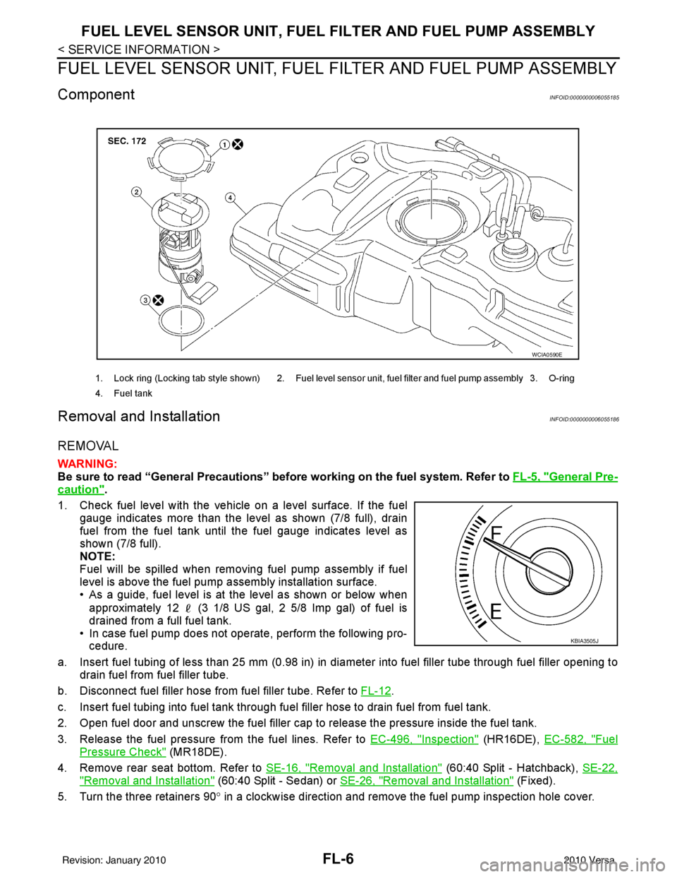
ComponentINFOID:0000000006055185
Removal and InstallationINFOID:0000000006055186
REMOVAL
WARNING:
Be sure to read “General Precautions” be fore working on the fuel system. Refer to FL-5, "
General Pre-
caution".
1. Check fuel level with the vehicle on a level surface. If the fuel gauge indicates more than the level as shown (7/8 full), drain
fuel from the fuel tank until the fuel gauge indicates level as
shown (7/8 full).
NOTE:
Fuel will be spilled when removing fuel pump assembly if fuel
level is above the fuel pump assembly installation surface.
• As a guide, fuel level is at the level as shown or below when
approximately 12 (3 1/8 US gal, 2 5/8 Imp gal) of fuel is
drained from a full fuel tank.
• In case fuel pump does not operate, perform the following pro- cedure.
a. Insert fuel tubing of less than 25 mm (0.98 in) in di ameter into fuel filler tube through fuel filler opening to
drain fuel from fuel filler tube.
b. Disconnect fuel filler hose from fuel filler tube. Refer to FL-12
.
c. Insert fuel tubing into fuel tank through f uel filler hose to drain fuel from fuel tank.
2. Open fuel door and unscrew the fuel filler cap to release the pressure inside the fuel tank.
3. Release the fuel pressure from the fuel lines. Refer to EC-496, "
Inspection" (HR16DE), EC-582, "Fuel
Pressure Check" (MR18DE).
4. Remove rear seat bottom. Refer to SE-16, "
Removal and Installation" (60:40 Split - Hatchback), SE-22,
"Removal and Installation" (60:40 Split - Sedan) or SE-26, "Removal and Installation" (Fixed).
5. Turn the three retainers 90 ° in a clockwise direction and remove the fuel pump inspection hole cover.
1. Lock ring (Locking tab style shown) 2. Fuel level sensor unit, fuel filter and fuel pump assembly 3. O-ring
4. Fuel tank
WCIA0590E
KBIA3505J
Revision: January 20102010 Versa
Page 2638 of 3745

FL-8
< SERVICE INFORMATION >
FUEL LEVEL SENSOR UNIT, FUEL FILTER AND FUEL PUMP ASSEMBLY
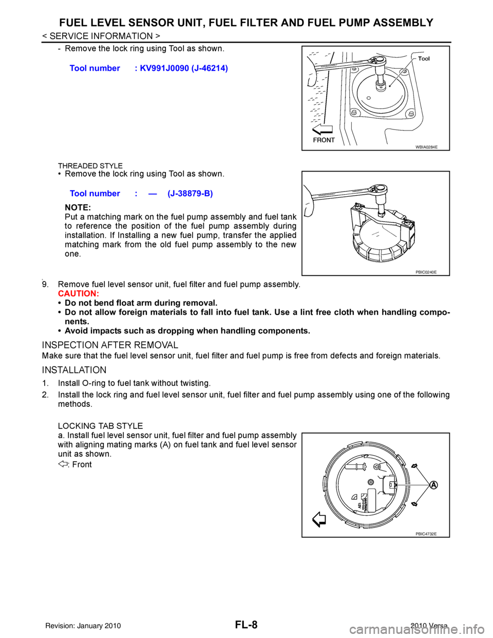
- Remove the lock ring using Tool as shown.
THREADED STYLE• Remove the lock ring using Tool as shown.
NOTE:
Put a matching mark on the fuel pump assembly and fuel tank
to reference the position of the fuel pump assembly during
installation. If Installing a new fuel pump, transfer the applied
matching mark from the old fuel pump assembly to the new
one.
8.9. Remove fuel level sensor unit, fuel filter and fuel pump assembly. CAUTION:
• Do not bend float arm during removal.
• Do not allow foreign materials to fall into fuel tank. Use a lint free cloth when handling compo-
nents.
• Avoid impacts such as dropping when handling components.
INSPECTION AFTER REMOVAL
Make sure that the fuel level sensor unit, fuel filter and fuel pump is free from defects and foreign materials.
INSTALLATION
1. Install O-ring to fuel tank without twisting.
2. Install the lock ring and fuel level sensor unit, fuel filter and fuel pump assembly using one of the following
methods.
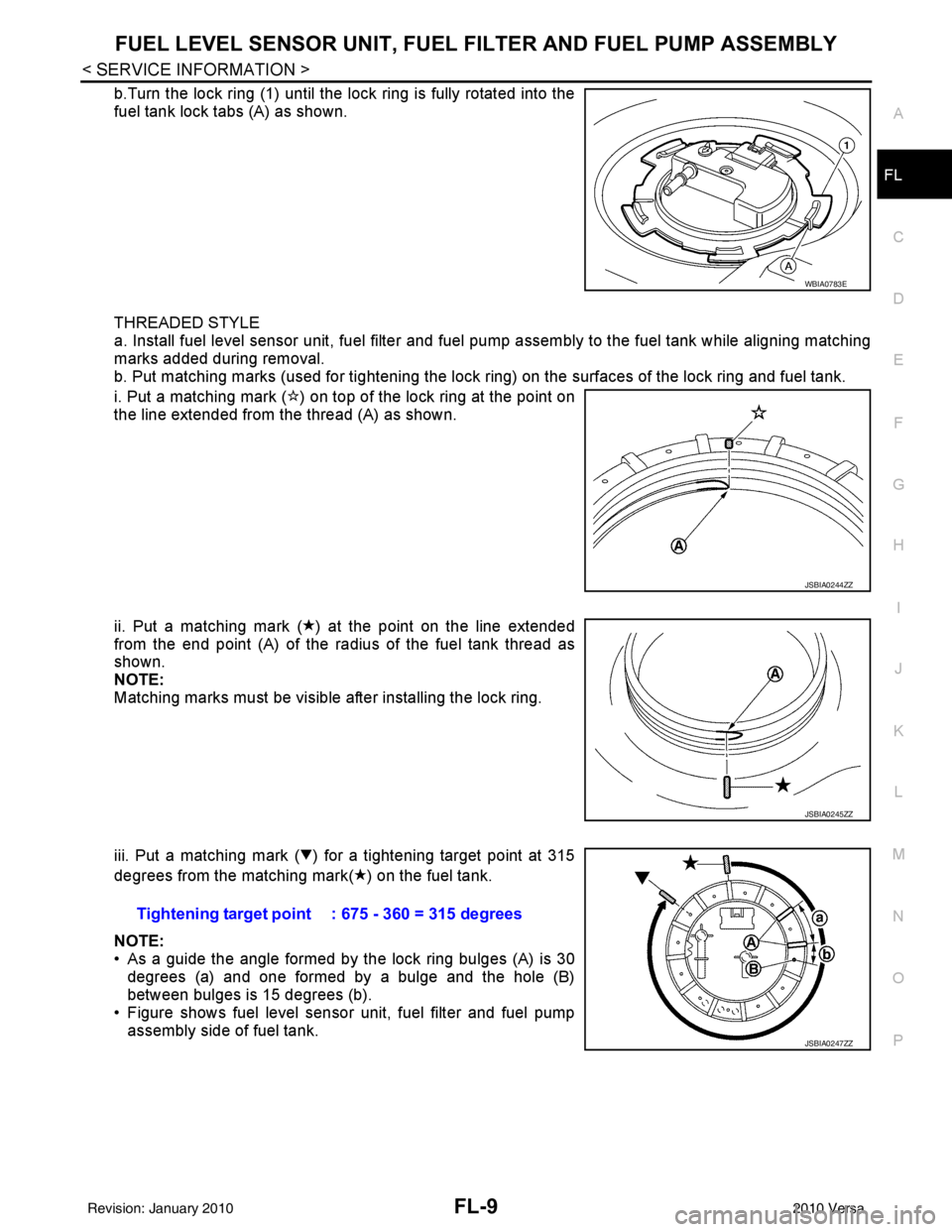
LOCKING TAB STYLE
a. Install fuel level sensor unit, fuel filter and fuel pump assembly
with aligning mating marks (A) on fuel tank and fuel level sensor
unit as shown.
: FrontTool number : KV991J0090 (J-46214)
WBIA0284E
Tool number : — (J-38879-B)
PBIC0240E
PBIC4732E
Revision: January 20102010 Versa
Page 2639 of 3745

FUEL LEVEL SENSOR UNIT, FUEL FILTER AND FUEL PUMP ASSEMBLYFL-9
< SERVICE INFORMATION >
C
DE
F
G H
I
J
K L
M A
FL
NP
O
b.Turn the lock ring (1) until the lock ring is fully rotated into the
fuel tank lock tabs (A) as shown.
THREADED STYLE
a. Install fuel level sensor unit, fuel filter and fuel pump assembly to the fuel tank while aligning matching
marks added during removal.
b. Put matching marks (used for ti
ghtening the lock ring) on the surfaces of the lock ring and fuel tank.
i. Put a matching mark ( ) on top of the lock ring at the point on
the line extended from the thread (A) as shown.
ii. Put a matching mark ( ) at the point on the line extended
from the end point (A) of the radius of the fuel tank thread as
shown.
NOTE:
Matching marks must be visible after installing the lock ring.
iii. Put a matching mark ( ) for a tightening target point at 315
degrees from the matching mark( ) on the fuel tank.
NOTE:
• As a guide the angle formed by the lock ring bulges (A) is 30 degrees (a) and one formed by a bulge and the hole (B)
between bulges is 15 degrees (b).
• Figure shows fuel level sensor unit, fuel filter and fuel pump assembly side of fuel tank.
WBIA0783E
JSBIA0244ZZ
JSBIA0245ZZ
Tightening target point : 675 - 360 = 315 degrees
JSBIA0247ZZ
Revision: January 20102010 Versa