2010 NISSAN TIIDA ignition
[x] Cancel search: ignitionPage 2772 of 3745
REAR WINDOW DEFOGGERGW-55
< SERVICE INFORMATION >
C
DE
F
G H
J
K L
M A
B
GW
N
O P
Terminal and Reference Value for BCMINFOID:0000000005396772
Refer to BCS-12, "Terminal and Reference Value for BCM" .
Terminal and Reference Value for IPDM E/RINFOID:0000000005396773
Refer to PG-25, "Terminal and Reference Value for IPDM E/R" .
Work FlowINFOID:0000000005396774
1. Check the symptom and customer's requests.
2. Understand the outline of system. Refer to GW-51, "
System Description" .
3. According to the trouble diagnosis chart, repair or replace the cause of the malfunction. Refer to GW-55,
"Trouble Diagnosis Symptom Chart" .
4. Does rear window defogger operate normally? YES: GO TO 5, NO: GO TO 3.
5. Inspection End.
CONSULT-III Function (BCM)INFOID:0000000005396775
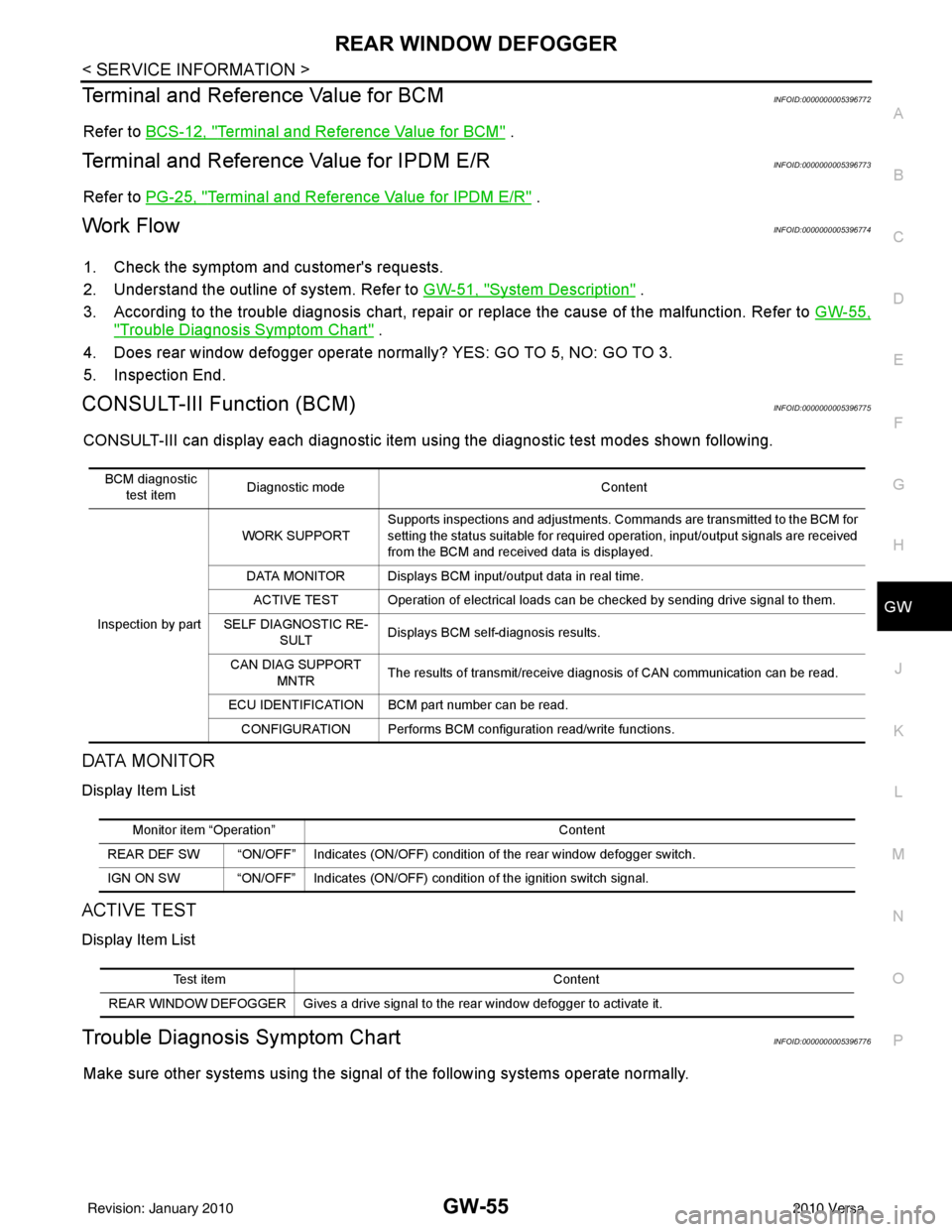
CONSULT-III can display each diagnostic item using the diagnostic test modes shown following.
DATA MONITOR
Display Item List
ACTIVE TEST
Display Item List
Trouble Diagnosis Symptom ChartINFOID:0000000005396776
Make sure other systems using the signal of the following systems operate normally.
BCM diagnostic
test item Diagnostic mode
Content
Inspection by part WORK SUPPORT
Supports inspections and adjustments. Commands are transmitted to the BCM for
setting the status suitable for required operation, input/output signals are received
from the BCM and received data is displayed.
DATA MONITOR Displays BCM input/output data in real time. ACTIVE TEST Operation of electrical loads can be checked by sending drive signal to them.
SELF DIAGNOSTIC RE- SULT Displays BCM self-diagnosis results.
CAN DIAG SUPPORT MNTR The results of transmit/receive diagnosis of CAN communication can be read.
ECU IDENTIFICATION BCM part number can be read. CONFIGURATION Performs BCM configuration read/write functions.
Monitor item “Operation” Content
REAR DEF SW “ON/OFF” Indicates (ON/OFF) condition of the rear window defogger switch.
IGN ON SW “ON/OFF” Indicates (ON/OFF) condition of the ignition switch signal.
Test item Content
REAR WINDOW DEFOGGER Gives a drive signal to the rear window defogger to activate it.
Revision: January 20102010 Versa
Page 2773 of 3745
GW-56
< SERVICE INFORMATION >
REAR WINDOW DEFOGGER
BCM Power Supply and Ground Circuit Inspection
INFOID:0000000005396777
Refer to BCS-16, "BCM Power Supply and Ground Circuit Inspection" .
Rear Window Defogger Swit ch Circuit InspectionINFOID:0000000005396778
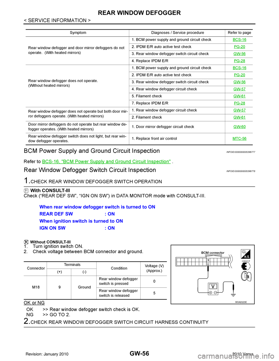
1.CHECK REAR WINDOW DEFOGGER SWITCH OPERATION
With CONSULT-III
Check (“REAR DEF SW”, “IGN ON SW”) in DATA MONITOR mode with CONSULT-III.
Without CONSULT-III
1. Turn ignition switch ON.
2. Check voltage between BCM connector and ground.
OK or NG
OK >> Rear window defogger switch check is OK.
NG >> GO TO 2.
2.CHECK REAR WINDOW DEFOGGER SWITCH CIRCUIT HARNESS CONTINUITY
Symptom Diagnoses / Service procedureRefer to page
Rear window defogger and door mirror defoggers do not
operate. (With heated mirrors) 1. BCM power supply and ground circuit check
BCS-16
2. IPDM E/R auto active test check PG-20
3. Rear window defogger switch circuit checkGW-56
4. Replace IPDM E/R PG-28
Rear window defogger does not operate.
(Without heated mirrors) 1. BCM power supply and ground circuit check
BCS-16
2. IPDM E/R auto active test check PG-20
3. Rear window defogger switch circuit checkGW-56
4. Rear window defogger circuit checkGW-57
5. Filament checkGW-61
7. Replace IPDM E/R PG-28
Rear window defogger does not operate but both door mir-
ror defoggers operate. (With heated mirrors) 1. Rear window defogger circuit check
GW-57
2. Filament checkGW-61
Door mirror defoggers do not operate but rear window de-
fogger operates. (With heated mirrors) 1. Door mirror defogger circuit check
GW-60
Rear window defogger switch does not light, but rear win-
dow defogger operates. 1. Replace front air control
MTC-56
When rear window defogger switch is turned to ON
REAR DEF SW: ON
When ignition switch is turned to ON
IGN ON SW : ON
ConnectorTe r m i n a l s
ConditionVoltage (V)
(Approx.)
(+) (-)
M18 9 Ground Rear window defogger
switch is pressed
0
Rear window defogger
switch is released 5
WIIA0523E
Revision: January 20102010 Versa
Page 2774 of 3745
REAR WINDOW DEFOGGERGW-57
< SERVICE INFORMATION >
C
DE
F
G H
J
K L
M A
B
GW
N
O P
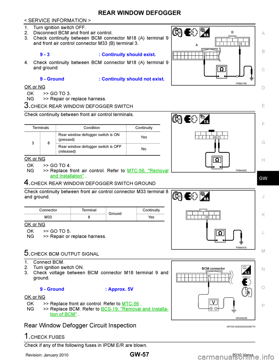
1. Turn ignition switch OFF.
2. Disconnect BCM and front air control.
3. Check continuity between BCM connector M18 (A) terminal 9 and front air control connector M33 (B) terminal 3.
4. Check continuity between BCM connector M18 (A) terminal 9 and ground
OK or NG
OK >> GO TO 3.
NG >> Repair or replace harness.
3.CHECK REAR WINDOW DEFOGGER SWITCH
Check continuity between fr ont air control terminals.
OK or NG
OK >> GO TO 4.
NG >> Replace front air control. Refer to MTC-56, "
Removal
and Installation" .
4.CHECK REAR WINDOW DEFOGGER SWITCH GROUND
Check continuity between front air control connector M33 terminal 8
and ground.
OK or NG
OK >> GO TO 5.
NG >> Repair or replace harness.
5.CHECK BCM OUTPUT SIGNAL
1. Connect BCM.
2. Turn ignition switch ON.
3. Check voltage between BCM connector M18 terminal 9 and ground.
OK or NG
OK >> Replace front air control. Refer to MTC-56 .
NG >> Replace BCM. Refer to BCS-19, "
Removal and Installa-
tion of BCM" .
Rear Window Defogger Circuit InspectionINFOID:0000000005396779
1.CHECK FUSES
Check if any of the following fuses in IPDM E/R are blown. 9 - 3
: Continuity should exist.
9 - Ground : Continuity should not exist.
PIIB6479E
Terminals Condition Continuity
38 Rear window defogger switch is ON
(pressed)
Ye s
Rear window defogger switch is OFF
(released) No
PIIB6480E
Connector
Terminal
Ground Continuity
8Y es
M33
PIIB6481E
9 - Ground : Approx. 5V
WIIA0523E
Revision: January 20102010 Versa
Page 2775 of 3745
GW-58
< SERVICE INFORMATION >
REAR WINDOW DEFOGGER
OK or NG
OK >> GO TO 2.
NG >> If fuse is blown, be sure to eliminate cause of malfunction before installing new fuse.
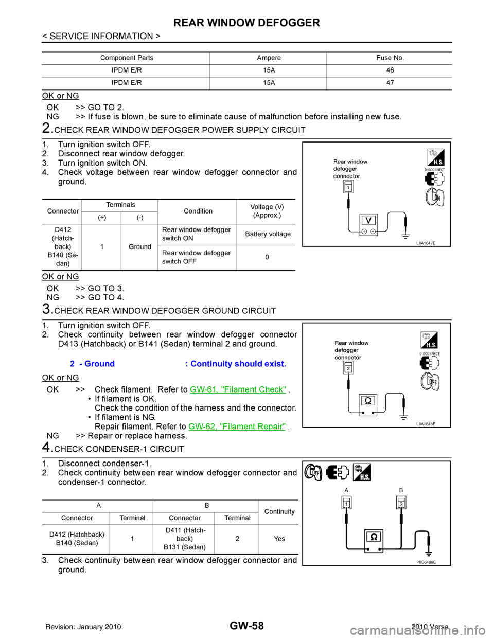
2.CHECK REAR WINDOW DEFOGGER POWER SUPPLY CIRCUIT
1. Turn ignition switch OFF.
2. Disconnect rear window defogger.
3. Turn ignition switch ON.
4. Check voltage between rear window defogger connector and ground.
OK or NG
OK >> GO TO 3.
NG >> GO TO 4.
3.CHECK REAR WINDOW DEFOGGER GROUND CIRCUIT
1. Turn ignition switch OFF.
2. Check continuity between rear window defogger connector D413 (Hatchback) or B141 (Sedan) terminal 2 and ground.
OK or NG
OK >> Check filament. Refer to GW-61, "Filament Check" .
• If filament is OK.
Check the condition of the harness and the connector.
• If filament is NG. Repair filament. Refer to GW-62, "
Filament Repair" .
NG >> Repair or replace harness.
4.CHECK CONDENSER-1 CIRCUIT
1. Disconnect condenser-1.
2. Check continuity between rear window defogger connector and condenser-1 connector.
3. Check continuity between rear window defogger connector and ground.
Component Parts AmpereFuse No.
IPDM E/R 15A46
IPDM E/R 15A47
ConnectorTe r m i n a l s
ConditionVoltage (V)
(Approx.)
(+) (-)
D412
(Hatch- back)
B140 (Se-
dan) 1Ground Rear window defogger
switch ON
Battery voltage
Rear window defogger
switch OFF 0
LIIA1847E
2 - Ground
: Continuity should exist.
LIIA1848E
AB
Continuity
Connector Terminal Connector Terminal
D412 (Hatchback) B140 (Sedan) 1 D411 (Hatch-
back)
B131 (Sedan) 2Y
es
PIIB6486E
Revision: January 20102010 Versa
Page 2776 of 3745
REAR WINDOW DEFOGGERGW-59
< SERVICE INFORMATION >
C
DE
F
G H
J
K L
M A
B
GW
N
O P
OK or NG
OK >> GO TO 5.
NG >> Repair or replace harness.
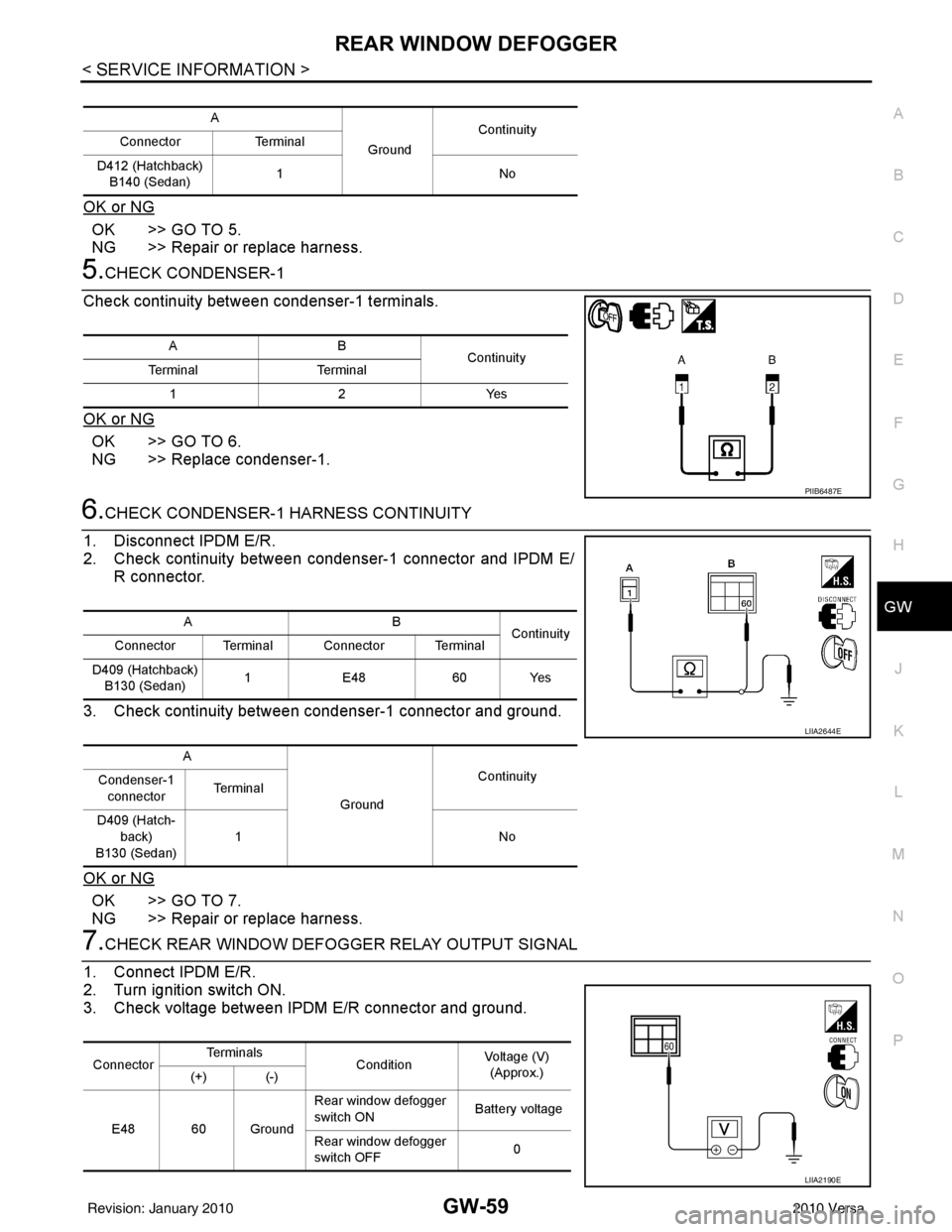
5.CHECK CONDENSER-1
Check continuity between condenser-1 terminals.
OK or NG
OK >> GO TO 6.
NG >> Replace condenser-1.
6.CHECK CONDENSER-1 HARNESS CONTINUITY
1. Disconnect IPDM E/R.
2. Check continuity between condenser-1 connector and IPDM E/ R connector.
3. Check continuity between condenser-1 connector and ground.
OK or NG
OK >> GO TO 7.
NG >> Repair or replace harness.
7.CHECK REAR WINDOW DEFOGGER RELAY OUTPUT SIGNAL
1. Connect IPDM E/R.
2. Turn ignition switch ON.
3. Check voltage between IPDM E/R connector and ground.
A
GroundContinuity
Connector Terminal
D412 (Hatchback) B140 (Sedan) 1N
o
AB
Continuity
Te r m i n a l Te r m i n a l
12Y es
PIIB6487E
AB
Continuity
Connector Terminal Connector Terminal
D409 (Hatchback) B130 (Sedan) 1
E48 60 Yes
A GroundContinuity
Condenser-1
connector Te r m i n a l
D409 (Hatch- back)
B130 (Sedan) 1N
o
LIIA2644E
ConnectorTe r m i n a l s
ConditionVoltage (V)
(Approx.)
(+) (-)
E48 60 Ground Rear window defogger
switch ON
Battery voltage
Rear window defogger
switch OFF 0
LIIA2190E
Revision: January 20102010 Versa
Page 2777 of 3745
GW-60
< SERVICE INFORMATION >
REAR WINDOW DEFOGGER
OK or NG
OK >> Check condition of harness and connector.
NG >> Replace IPDM E/R. Refer to PG-28, "
Removal and Installation of IPDM E/R" .
Door Mirror Defogger Circuit InspectionINFOID:0000000005396780
1.CHECK FUSE
Check if the following fuse in the fuse block (J/B) is blown.
OK or NG
OK >> GO TO 2.
NG >> If fuse is blown, be sure to eliminate cause of malfunction before installing new fuse.
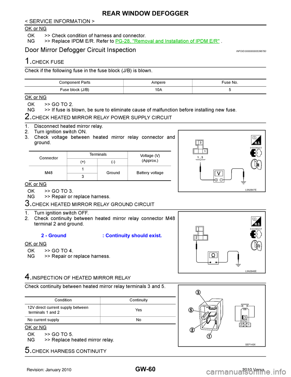
2.CHECK HEATED MIRROR RELAY POWER SUPPLY CIRCUIT
1. Disconnect heated mirror relay.
2. Turn ignition switch ON.
3. Check voltage between heated mirror relay connector and ground.
OK or NG
OK >> GO TO 3.
NG >> Repair or replace harness.
3.CHECK HEATED MIRROR RELAY GROUND CIRCUIT
1. Turn ignition switch OFF.
2. Check continuity between heated mirror relay connector M48 terminal 2 and ground.
OK or NG
OK >> GO TO 4.
NG >> Repair or replace harness.
4.INSPECTION OF HEATED MIRROR RELAY
Check continuity between heated mirror relay terminals 3 and 5.
OK or NG
OK >> GO TO 5.
NG >> Replace heated mirror relay.
5.CHECK HARNESS CONTINUITY
Component Parts AmpereFuse No.
Fuse block (J/B) 10A5
ConnectorTe r m i n a l s
Voltage (V)
(Approx.)
(+) (-)
M48 1
Ground Battery voltage
3
LIIA2647E
2 - Ground : Continuity should exist.
LIIA2646E
Condition Continuity
12V direct current supply between
terminals 1 and 2 Ye s
No current supply No
SEF145X
Revision: January 20102010 Versa
Page 2786 of 3745

IP-2
< PRECAUTION >
PRECAUTIONS
PRECAUTION
PRECAUTIONS
Precaution for Supplemental Restraint System (SRS) "AIR BAG" and "SEAT BELT
PRE-TENSIONER"
INFOID:0000000005714401
The Supplemental Restraint System such as “A IR BAG” and “SEAT BELT PRE-TENSIONER”, used along
with a front seat belt, helps to reduce the risk or severity of injury to the driver and front passenger for certain
types of collision. This system includes seat belt switch inputs and dual stage front air bag modules. The SRS
system uses the seat belt switches to determine the front air bag deployment, and may only deploy one front
air bag, depending on the severity of a collision and w hether the front occupants are belted or unbelted.
Information necessary to service the system safely is included in the SRS and SB section of this Service Man-
ual.
WARNING:
• To avoid rendering the SRS inopera tive, which could increase the risk of personal injury or death in
the event of a collision which would result in air bag inflation, all maintenance must be performed by
an authorized NISSAN/INFINITI dealer.
• Improper maintenance, including in correct removal and installation of the SRS, can lead to personal
injury caused by unintent ional activation of the system. For re moval of Spiral Cable and Air Bag
Module, see the SRS section.
• Do not use electrical test equipmen t on any circuit related to the SRS unless instructed to in this
Service Manual. SRS wiring harn esses can be identified by yellow and/or orange harnesses or har-
ness connectors.
PRECAUTIONS WHEN USING POWER TOOLS (AIR OR ELECTRIC) AND HAMMERS
WARNING:
• When working near the Airbag Diagnosis Sensor Unit or other Airbag System sensors with the Igni-
tion ON or engine running, DO NOT use air or electri c power tools or strike near the sensor(s) with a
hammer. Heavy vibration could activate the sensor( s) and deploy the air bag(s), possibly causing
serious injury.
• When using air or electric power tools or hammers , always switch the Ignition OFF, disconnect the
battery, and wait at least 3 minu tes before performing any service.
Precaution Necessary for Steering W heel Rotation After Battery Disconnect
INFOID:0000000005396849
NOTE:
• This Procedure is applied only to models with Intelligent Key system and NATS (NISSAN ANTI-THEFT SYS-
TEM).
• Remove and install all control units after disconnecting both battery cables with the ignition knob in the
″LOCK ″ position.
• Always use CONSULT-III to perform self-diagnosis as a part of each function inspection after finishing work.
If DTC is detected, perform trouble diagnosis according to self-diagnostic results.
For models equipped with the Intelligent Key system and NATS, an electrically controlled steering lock mech-
anism is adopted on the key cylinder.
For this reason, if the battery is disconnected or if the battery is discharged, the steering wheel will lock and
steering wheel rotation will become impossible.
If steering wheel rotation is required when battery pow er is interrupted, follow the procedure below before
starting the repair operation.
OPERATION PROCEDURE
1. Connect both battery cables. NOTE:
Supply power using jumper cables if battery is discharged.
2. Use the Intelligent Key or mechanical key to turn the ignition switch to the ″ACC ″ position. At this time, the
steering lock will be released.
3. Disconnect both battery cables. The steering lock will remain released and the steering wheel can be rotated.
4. Perform the necessary repair operation.
Revision: January 20102010 Versa
Page 2787 of 3745

PRECAUTIONSIP-3
< PRECAUTION >
C
DE
F
G H
J
K L
M A
B
IP
N
O P
5. When the repair work is completed, return the ignition switch to the ″LOCK ″ position before connecting
the battery cables. (At this time, the steering lock mechanism will engage.)
6. Perform a self-diagnosis check of al l control units using CONSULT-III.
PrecautionINFOID:0000000005396850
• Disconnect both battery terminals in advance.
• Disconnect air bag system line in advance.
• Never tamper with or force air bag lid open, as this may adversely affect air bag performance.
• Be careful not to scratch pad and other parts.
• When removing or disassembling any part, be careful not to damage or deform it. Protect parts which may
get in the way with cloth.
• When removing parts, protect parts by wrapping tools with vinyl or tape.
• Keep removed parts protected with cloth.
• If a clip is deformed or damaged, replace it.
• If an non-reusable part is removed, replace it with a new one.
• Tighten bolts and nuts firmly to the specified torque.
• After re-assembly has been completed, make sure each part functions correctly.
• Remove stains in the following way.
Water-soluble stains:
Dip a soft cloth in warm water, and then squeeze it tight ly. After wiping the stain, wipe with a soft dry cloth.
Oil stain:
Dissolve a synthetic detergent in warm water (density of 2 to 3% or less), dip the cloth, then clean off the stain
with the cloth. Next, dip the cloth in fresh water and squeeze it tightly. Then clean off the detergent completely.
Then wipe the area with a soft dry cloth.
• Do not use any organic solvent, such as thinner or benzine.
Revision: January 20102010 Versa