2010 NISSAN TIIDA ignition
[x] Cancel search: ignitionPage 2695 of 3745

SERVICE INFORMATION FOR ELECTRICAL INCIDENTGI-29
< SERVICE INFORMATION >
C
DE
F
G H
I
J
K L
M B
GI
N
O P
• Close the relay and probe at the solenoid. voltage; open is further down the circuit than the solenoid.
no voltage; open is between relay and solenoid (point C).
Any powered circuit can be diagnosed using the approach in the previous example.
Testing for “Shorts” in the Circuit
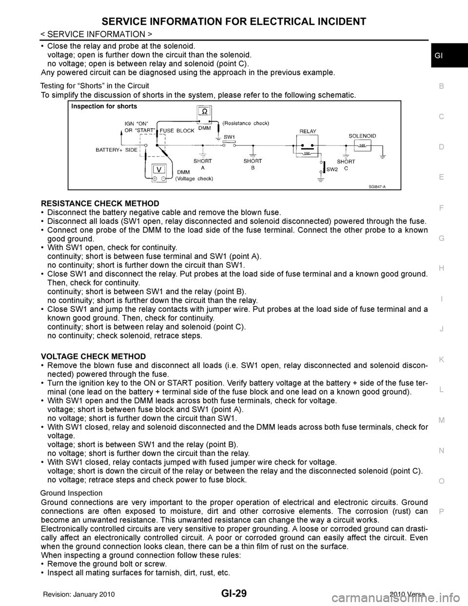
To simplify the discussion of shorts in the system, please refer to the following schematic.
RESISTANCE CHECK METHOD
• Disconnect the battery negative cable and remove the blown fuse.
• Disconnect all loads (SW1 open, relay disconnected and solenoid disconnected) powered through the fuse.
• Connect one probe of the DMM to the load side of the fuse terminal. Connect the other probe to a known
good ground.
• With SW1 open, check for continuity.
continuity; short is between fuse terminal and SW1 (point A).
no continuity; short is further down the circuit than SW1.
• Close SW1 and disconnect the relay. Put probes at the load side of fuse terminal and a known good ground.
Then, check for continuity.
continuity; short is between SW1 and the relay (point B).
no continuity; short is further down the circuit than the relay.
• Close SW1 and jump the relay contacts with jumper wir e. Put probes at the load side of fuse terminal and a
known good ground. Then, check for continuity.
continuity; short is between relay and solenoid (point C).
no continuity; check solenoid, retrace steps.
VOLTAGE CHECK METHOD
• Remove the blown fuse and disconnect all loads (i .e. SW1 open, relay disconnected and solenoid discon-
nected) powered through the fuse.
• Turn the ignition key to the ON or START position. Veri fy battery voltage at the battery + side of the fuse ter-
minal (one lead on the battery + terminal side of the fuse block and one lead on a known good ground).
• With SW1 open and the DMM leads across both fuse terminals, check for voltage.
voltage; short is between fuse block and SW1 (point A).
no voltage; short is further down the circuit than SW1.
• With SW1 closed, relay and solenoid disconnected and the DMM leads across both fuse terminals, check for voltage.
voltage; short is between SW1 and the relay (point B).
no voltage; short is further down the circuit than the relay.
• With SW1 closed, relay contacts jumped with fused jumper wire check for voltage.
voltage; short is down the circuit of the relay or between the relay and the disconnected solenoid (point C).
no voltage; retrace steps and check power to fuse block.
Ground Inspection
Ground connections are very important to the proper oper ation of electrical and electronic circuits. Ground
connections are often exposed to moisture, dirt and other corrosive elements. The corrosion (rust) can
become an unwanted resistance. This unwanted resistance can change the way a circuit works.
Electronically controlled circuits are very sensitive to proper grounding. A loose or corroded ground can drasti-
cally affect an electronically controlled circuit. A poor or corroded ground can easily affect the circuit. Even
when the ground connection looks clean, there can be a thin film of rust on the surface.
When inspecting a ground connection follow these rules:
• Remove the ground bolt or screw.
• Inspect all mating surfaces for tarnish, dirt, rust, etc.
SGI847-A
Revision: January 20102010 Versa
Page 2714 of 3745

GI-48
< SERVICE INFORMATION >
TERMINOLOGY
TERMINOLOGY
SAE J1930 Terminology ListINFOID:0000000005399867
All emission related terms used in this publication in accordance with SAE J1930 are listed. Accordingly, new
terms, new acronyms/abbreviations and old terms are listed in the following chart.
NEW TERMNEW ACRONYM /
ABBREVIATION OLD TERM
Air cleaner ACL Air cleaner
Barometric pressure BARO ***
Barometric pressure sensor-BCDD BAROS-BCDD BCDD
Camshaft position CMP ***
Camshaft position sensor CMPSCrank angle sensor
Canister *** Canister
Carburetor CARBCarburetor
Charge air cooler CACIntercooler
Closed loop CLClosed loop
Closed throttle position switch CTP switchIdle switch
Clutch pedal position switch CPP switch Clutch switch
Continuous fuel injection system CFI system***
Continuous trap oxidizer system CTOX system ***
Crankshaft position CKP***
Crankshaft position sensor CKPS***
Data link connector DLC***
Data link connector for CONSULT-III DLC for CONSULT-IIIDiagnostic connector for CONSULT-III
Diagnostic test mode DTMDiagnostic mode
Diagnostic test mode selector DTM selectorDiagnostic mode selector
Diagnostic test mode I DTM I Mode I
Diagnostic test mode II DTM IIMode II
Diagnostic trouble code DTCMalfunction code
Direct fuel injection system DFI system ***
Distributor ignition system DI system Ignition timing control
Early fuel evaporation-mixture heater EFE-mixture heater Mixture heater
Early fuel evaporation system EFE system Mixture heater control
Electrically erasable programmable read
only memory EEPROM
***
Electronic ignition system EI systemIgnition timing control
Engine control EC ***
Engine control module ECM ECCS control unit
Engine coolant temperature ECT Engine temperature
Engine coolant temperature sensor ECTS Engine temperature sensor
Engine modification EM ***
Engine speed RPM Engine speed
Erasable programmable read only memory EPROM ***
Evaporative emission canister EVAP canister Canister
Evaporative emission system EVAP system Canister control solenoid valve
Exhaust gas recirculation valve EGR valve EGR valve
Revision: January 20102010 Versa
Page 2715 of 3745

TERMINOLOGYGI-49
< SERVICE INFORMATION >
C
DE
F
G H
I
J
K L
M B
GI
N
O P
Exhaust gas recirculation control-BPT
valve EGRC-BPT valve
BPT valve
Exhaust gas recirculation control-solenoid
valve EGRC-solenoid valve
EGR control solenoid valve
Exhaust gas recirculation temperature sen-
sor EGRT sensorExhaust gas temperature sensor
EGR temperature sensor
Flash electrically erasable programmable
read only memory FEEPROM
***
Flash erasable programmable read only
memory FEPROM
***
Flexible fuel sensor FFS***
Flexible fuel system FF system***
Fuel pressure regulato r*** Pressure regulator
Fuel pressure regulator control solenoid
valve ***
PRVR control solenoid valve
Fuel trim FT***
Heated Oxygen sensor HO2S Exhaust gas sensor
Idle air control system IAC system Idle speed control
Idle air control valve-air regulato rIACV-air regulator Air regulator
Idle air control valve-auxiliary air control
valve IACV-AAC valve
Auxiliary air control (AAC) valve
Idle air control valve-FICD solenoid valve IACV-FICD solenoid valve FICD solenoid valve
Idle air control valve-idle up control sole-
noid valve IACV-idle up control solenoid valve Idle up control solenoid valve
Idle speed control-FI pot ISC-FI pot FI pot
Idle speed control system ISC system***
Ignition control IC***
Ignition control module ICM***
Indirect fuel injection system IFI system ***
Intake air IA Air
Intake air temperature sensor IAT sensor Air temperature sensor
Knock *** Detonation
Knock sensor KS Detonation sensor
Malfunction indicator lamp MIL Check engine light
Manifold absolute pressure MAP ***
Manifold absolute pressure sensor MAPS ***
Manifold differential pressure MDP ***
Manifold differential pressure sensor MDPS ***
Manifold su rface temperature MST ***
Manifold surface temperature sensor MSTS ***
Manifold vacuum zone MVZ ***
Manifold vacuum zone sensor MVZS***
Mass air flow sensor MAFS Air flow meter
Mixture control solenoid valve MC solenoid valveAir-fuel ratio control solenoid valve
Multiport fuel injection System MFI system Fuel injection control
NEW TERM
NEW ACRONYM /
ABBREVIATION OLD TERM
Revision: January 20102010 Versa
Page 2720 of 3745

PRECAUTIONSGW-3
< SERVICE INFORMATION >
C
DE
F
G H
J
K L
M A
B
GW
N
O P
SERVICE INFORMATION
PRECAUTIONS
Precaution for Supplemental Restraint System (SRS) "AIR BAG" and "SEAT BELT
PRE-TENSIONER"
INFOID:0000000005777023
The Supplemental Restraint System such as “AIR BAG” and “SEAT BELT PRE-TENSIONER”, used along
with a front seat belt, helps to reduce the risk or severi ty of injury to the driver and front passenger for certain
types of collision. This system includes seat belt switch inputs and dual stage front air bag modules. The SRS
system uses the seat belt switches to determine the front air bag deployment, and may only deploy one front
air bag, depending on the severity of a collision and w hether the front occupants are belted or unbelted.
Information necessary to service the system safely is included in the SRS and SB section of this Service Man-
ual.
WARNING:
• To avoid rendering the SRS inoper ative, which could increase the risk of personal injury or death in
the event of a collision which would result in air bag inflation, all maintenance must be performed by
an authorized NISSAN/INFINITI dealer.
• Improper maintenance, including in correct removal and installation of the SRS can lead to personal
injury caused by unintentional act ivation of the system. For removal of Spiral Cable and Air Bag
Module, see the SRS section.
• Do not use electrical test equipm ent on any circuit related to the SRS unless instructed to in this
Service Manual. SRS wiring harnesses can be identi fied by yellow and/or orange harnesses or har-
ness connectors.
PRECAUTIONS WHEN USING POWER TOOLS (AIR OR ELECTRIC) AND HAMMERS
WARNING:
• When working near the Airbag Diagnosis Sensor Un it or other Airbag System sensors with the Igni-
tion ON or engine running, DO NOT use air or el ectric power tools or strike near the sensor(s) with a
hammer. Heavy vibration could activate the sensor( s) and deploy the air bag(s), possibly causing
serious injury.
• When using air or electric power tools or hammers, always switch the Ignition OFF, disconnect the battery, and wait at least 3 minutes before performing any service.
Precaution Necessary for Steering Wheel Rotation After Battery Disconnect
INFOID:0000000005396729
NOTE:
• This Procedure is applied only to models with Intelligent Key system and NATS (NISSAN ANTI-THEFT SYS-
TEM).
• Remove and install all control units after disconnecti ng both battery cables with the ignition knob in the
″ LOCK ″ position.
• Always use CONSULT-III to perform self-diagnosis as a part of each function inspection after finishing work.
If DTC is detected, perform trouble diagnosis according to self-diagnostic results.
For models equipped with the Intelligent Key system and NATS , an electrically controlled steering lock mech-
anism is adopted on the key cylinder.
For this reason, if the battery is disconnected or if the battery is discharged, the steering wheel will lock and
steering wheel rotation will become impossible.
If steering wheel rotation is required when battery power is interrupted, follow the procedure below before
starting the repair operation.
OPERATION PROCEDURE
1. Connect both battery cables. NOTE:
Supply power using jumper cables if battery is discharged.
2. Use the Intelligent Key or mechanical key to turn the ignition switch to the ″ACC ″ position. At this time, the
steering lock will be released.
3. Disconnect both battery cables. The steering lock will remain released and the steering wheel can be
rotated.
4. Perform the necessary repair operation.
Revision: January 20102010 Versa
Page 2721 of 3745

GW-4
< SERVICE INFORMATION >
PRECAUTIONS
5. When the repair work is completed, return the ignition switch to the ″LOCK ″ position before connecting
the battery cables. (At this time, the steering lock mechanism will engage.)
6. Perform a self-diagnosis check of a ll control units using CONSULT-III.
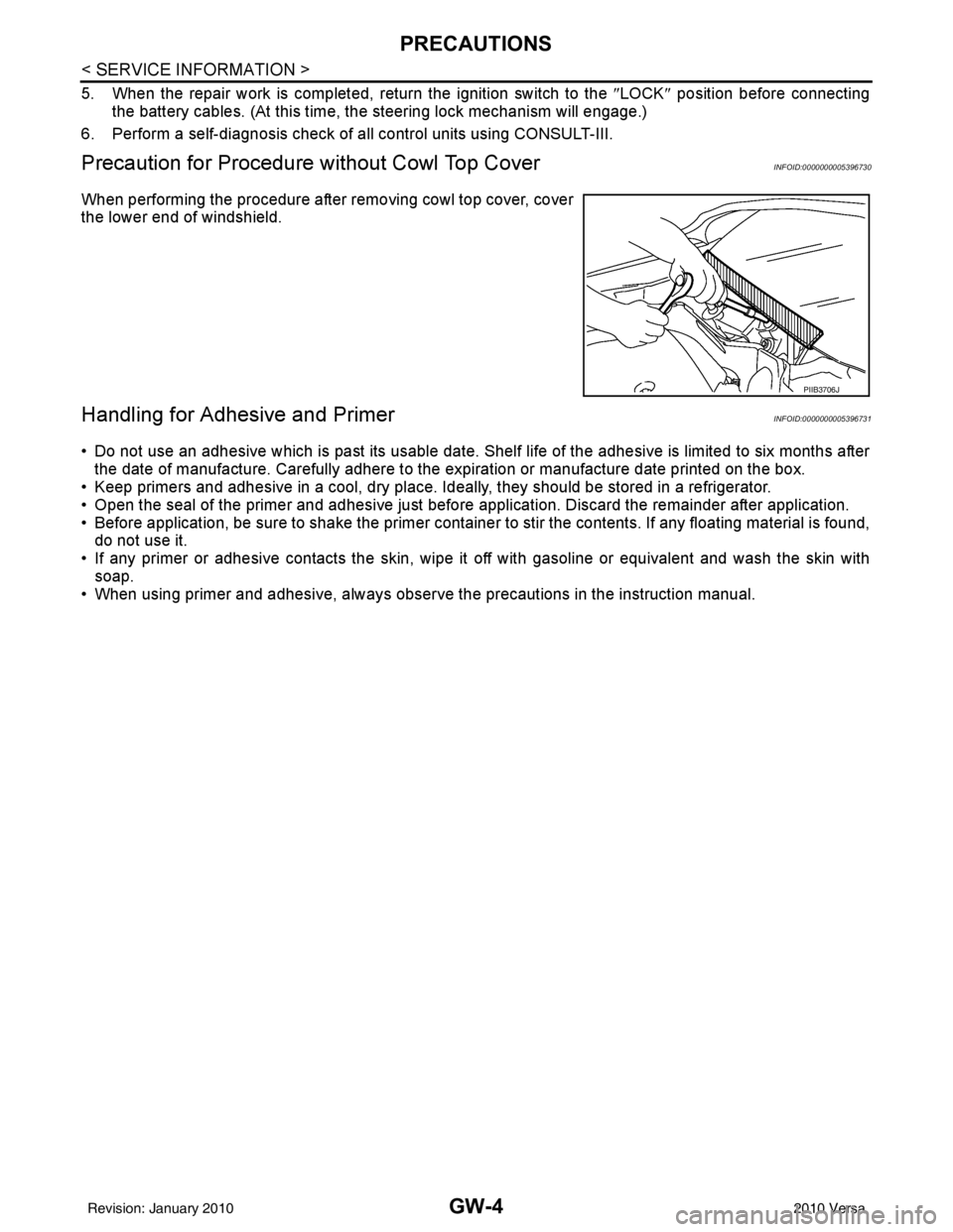
Precaution for Procedure without Cowl Top CoverINFOID:0000000005396730
When performing the procedure after removing cowl top cover, cover
the lower end of windshield.
Handling for Adhesive and PrimerINFOID:0000000005396731
• Do not use an adhesive which is past its usable date. Shel f life of the adhesive is limited to six months after
the date of manufacture. Carefully adhere to the expiration or manufacture date printed on the box.
• Keep primers and adhesive in a cool, dry place. Ideally, they should be stored in a refrigerator.
• Open the seal of the primer and adhesive just before application. Discard the remainder after application.
• Before application, be sure to shake the primer container to stir the contents. If any floating material is found, do not use it.
• If any primer or adhesive contacts the skin, wipe it off with gasoline or equivalent and wash the skin with
soap.
• When using primer and adhesive, always observe the precautions in the instruction manual.
PIIB3706J
Revision: January 20102010 Versa
Page 2736 of 3745

POWER WINDOW SYSTEMGW-19
< SERVICE INFORMATION >
C
DE
F
G H
J
K L
M A
B
GW
N
O P
POWER WINDOW SYSTEM
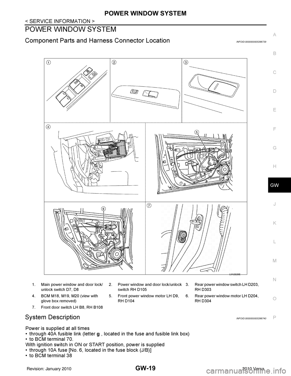
Component Parts and Har ness Connector LocationINFOID:0000000005396739
System DescriptionINFOID:0000000005396740
Power is supplied at all times
• through 40A fusible link (letter g , located in the fuse and fusible link box)
• to BCM terminal 70.
With ignition switch in ON or START position, power is supplied
• through 10A fuse [No. 6, located in the fuse block (J/B)]
• to BCM terminal 38
1. Main power window and door lock/
unlock switch D7, D8 2. Power window and door lock/unlock
switch RH D105 3. Rear power window switch LH D203,
RH D303
4. BCM M18, M19, M20 (view with glove box removed) 5. Front power window motor LH D9,
RH D104 6. Rear power window motor LH D204,
RH D304
7. Front door switch LH B8, RH B108
LIIA2529E
Revision: January 20102010 Versa
Page 2737 of 3745

GW-20
< SERVICE INFORMATION >
POWER WINDOW SYSTEM
• through BCM terminal 68
• to main power window and door lock/unlock switch terminal 10
• to power window and door lock/unlock switch RH terminal 8 and
• to rear power window switches LH and RH terminal 1.
Ground is supplied
• to BCM terminal 67
• to main power window and door lock/unlock switch terminal 17 and
• to power window and door lock/unlock switch RH terminal 3
• through body grounds M57 and M61.
With ignition switch in ACC or ON position, power is supplied
• through 10A fuse [No. 20, located in the fuse block (J/B)]
• to BCM terminal 11.
MANUAL OPERATION
Front Door LH
WINDOW UP
When the front LH switch in the main power window and door lock/unlock switch is pulled in the up position,
power is supplied
• through main power window and door lock/unlock switch terminal 8
• to front power window motor LH terminal 2.
Ground is supplied
• through main power window and door lock/unlock switch terminal 11
• to front power window motor LH terminal 3.
Then, the motor raises the window until the switch is released.
WINDOW DOWN
When the front LH switch in the main power window and door lock/unlock switch is pressed in the down posi-
tion, power is supplied
• through main power window and door lock/unlock switch terminal 11
• to front power window motor LH terminal 3.
Ground is supplied
• through main power window and door lock/unlock switch terminal 8
• to front power window motor LH terminal 2.
Then, the motor lowers the window until the switch is released.
Front Door RH
POWER WINDOW AND DOOR LOCK/ UNLOCK SWITCH RH OPERATION
WINDOW UP
When the power window and door lock/unlock switch RH is pulled in the up position, power is supplied
• through power window and door lock/unlock switch RH terminal 7
• to front power window motor RH terminal 2.
Ground is supplied
• through power window and door lock/unlock switch RH terminal 6
• to front power window motor RH terminal 1.
Then, the motor raises the window until the switch is released.
WINDOW DOWN
When the power window and door lock/unlock switch RH is pressed in the down position, power is supplied
• through power window and door lock/unlock switch RH terminal 6
• to front power window motor RH terminal 1.
Ground is supplied
• through power window and door lock/unlock switch RH terminal 7
• to front power window motor RH terminal 2.
Then, the motor lowers the window until the switch is released.
MAIN POWER WINDOW AND DOOR LOCK/UNLOCK SWITCH OPERATION
WINDOW UP
When the main power window and door lock/unlock switch (front RH) is pulled in the up position, power is sup-
plied
• through main power window and door lock/unlock switch terminal 16
• to power window and door lock/unlock switch RH terminal 12
• through power window and door lock/unlock switch RH terminal 7
• to front power window motor RH terminal 2.
Ground is supplied
Revision: January 20102010 Versa
Page 2739 of 3745

GW-22
< SERVICE INFORMATION >
POWER WINDOW SYSTEM
Then, the motor raises the window until the switch is released.
WINDOW DOWN
When the main power window and door lock/unlock switch (rear LH) is pressed in the down position, power is
supplied
• through main power window and door lock/unlock switch terminal 3
• to rear power window switch LH terminal 3
• through rear power window switch LH terminal 4
• to rear power window motor LH terminal 1.
Ground is supplied
• through main power window and door lock/unlock switch terminal 1
• to rear power window switch LH terminal 2
• through rear power window switch LH terminal 5
• to rear power window motor LH terminal 2.
Then, the motor lowers the window until the switch is released.
When the main power window and door lock/unlock switch (rear RH) is pressed in the down position, power is
supplied
• through main power window and door lock/unlock switch terminal 5
• to rear power window switch RH terminal 3
• through rear power window switch RH terminal 4
• to rear power window motor RH terminal 1.
Ground is supplied
• through main power window and door lock/unlock switch terminal 7
• to rear power window switch RH terminal 2
• through rear power window switch RH terminal 5
• to rear power window motor RH terminal 2.
Then, the motor lowers the window until the switch is released.
AUTO OPERATION
The power window AUTO feature enables the driver to open the window without holding the window switch in
the down position.
POWER WINDOW LOCK
The power window lock is designed to lock operation of all windows except for front door window LH.
When in the lock position, the power window lock di sables power window and door lock/unlock switch RH and
rear power window switch LH and RH by disconnecting switch ground signal. This prevents the power window
motors from operating.
RETAINED POWER OPERATION
When the ignition switch is turned to the OFF position from ON or START position, power is supplied for 45
seconds
• through BCM terminal 68
• to main power window and door lock/unlock switch terminal 10
• to power window and door lock/unlock switch RH terminal 8 and
• to rear power window switches LH and RH terminal 1.
When power and ground are supplied, the BCM conti nues to be energized, and the power window can be
operated.
The retained power operation is canceled when the front LH or front RH door is opened.
Retained power operation period can be changed by CONSULT-III. Refer to GW-30, "
CONSULT-III Function
(BCM)" .
ANTI-PINCH SYSTEM
Main power window and door lock/unlock switch monitors the power window motor operation and the power
window position (full closed or other) for front LH power window by the signal from encoder in front power win-
dow motor LH.
When main power window and door lock/unlock switch detects interruption during the following close opera-
tions
• automatic close operation when igniti on switch is in the ON position
• automatic close operation during retained power operation
Main power window and door lock/unlock switch controls front power window motor LH for open and the
power window will be lowered.
Revision: January 20102010 Versa