2010 NISSAN TIIDA service indicator
[x] Cancel search: service indicatorPage 757 of 3745
BL-248
< SERVICE INFORMATION >
NATS (NISSAN ANTI-THEFT SYSTEM)
NATS (NISSAN ANTI-THEFT SYSTEM)
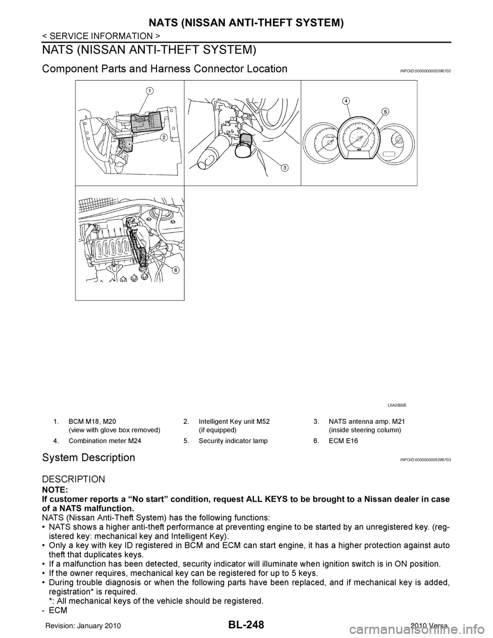
Component Parts and Harness Connector LocationINFOID:0000000005396702
System DescriptionINFOID:0000000005396703
DESCRIPTION
NOTE:
If customer reports a “No start” condition, request ALL KEYS to be brought to a Nissan dealer in case
of a NATS malfunction.
NATS (Nissan Anti-Theft System) has the following functions:
• NATS shows a higher anti-theft performance at preventing engine to be started by an unregistered key. (reg- istered key: mechanical key and Intelligent Key).
• Only a key with key ID registered in BCM and ECM c an start engine, it has a higher protection against auto
theft that duplicates keys.
• If a malfunction has been detected, security indicator will illuminate when ignition switch is in ON position.
• If the owner requires, mechanical key can be registered for up to 5 keys.
• During trouble diagnosis or when the following parts have been replaced, and if mechanical key is added,
registration* is required.
*: All mechanical keys of the vehicle should be registered.
-ECM
LIIA2920E
1. BCM M18, M20
(view with glove box removed) 2. Intelligent Key unit M52
(if equipped) 3. NATS antenna amp. M21
(inside steering column)
4. Combination meter M24 5. Security indicator lamp6. ECM E16
Revision: January 20102010 Versa
Page 758 of 3745
NATS (NISSAN ANTI-THEFT SYSTEM)BL-249
< SERVICE INFORMATION >
C
DE
F
G H
J
K L
M A
B
BL
N
O P
-BCM
- Mechanical key
• NATS trouble diagnoses, system initialization and additional registration of other NATS mechanical key IDs
must be carried out using CONSULT-III hardware and CONSULT-III NATS software. When NATS initializa-
tion has been completed, the ID of the inserted mechanical key can be displayed.
Regarding the procedures of NATS initialization and mechanical key ID registration, refer to CONSULT-III
operation manual NATS.
SECURITY INDICATOR
• Forewarns that the vehicle is equipped with NATS.
• Security indicator will not blink while the ignition knob is in ON or START state. NOTE:
Because security indicator is highly efficient, the battery is barely affected.
Condition of Secu rity Indicator
• When operating the ignition switch with Intelligent Key, security indicator lamp will turn off at once if ignition
switch is pressed and blinks when ignition switch is released.
• When operating the ignition switch with mechanical key security indicator will turn off at once if mechanical key is inserted into key cylinder and blinks when mechanical key is removed.
(Once the mechanical key is inserted into key cylinder, BCM will only perform the key ID verification with
mechanical key)
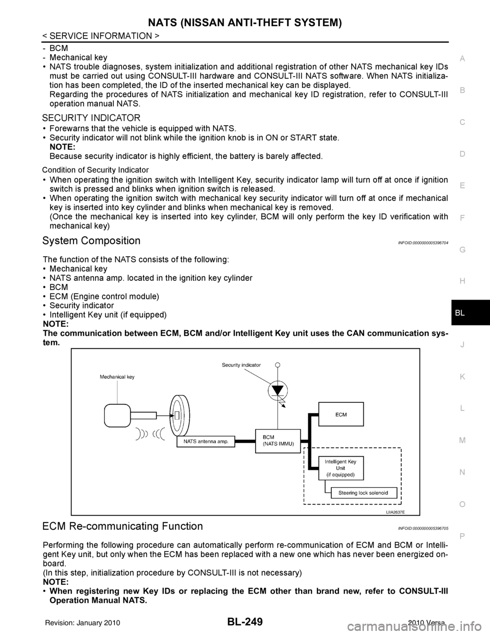
System CompositionINFOID:0000000005396704
The function of the NATS consists of the following:
• Mechanical key
• NATS antenna amp. located in the ignition key cylinder
•BCM
• ECM (Engine control module)
• Security indicator
• Intelligent Key unit (if equipped)
NOTE:
The communication between ECM, BCM and/or Intelligent K ey unit uses the CAN communication sys-
tem.
ECM Re-communicating FunctionINFOID:0000000005396705
Performing the following procedure can automatically perform re-communication of ECM and BCM or Intelli-
gent Key unit, but only when the ECM has been replaced with a new one which has never been energized on-
board.
(In this step, initialization procedur e by CONSULT-III is not necessary)
NOTE:
• When registering new Key IDs or replacing the ECM other than brand new, refer to CONSULT-III
Operation Manual NATS.
LIIA2637E
Revision: January 20102010 Versa
Page 762 of 3745
NATS (NISSAN ANTI-THEFT SYSTEM)BL-253
< SERVICE INFORMATION >
C
DE
F
G H
J
K L
M A
B
BL
N
O P
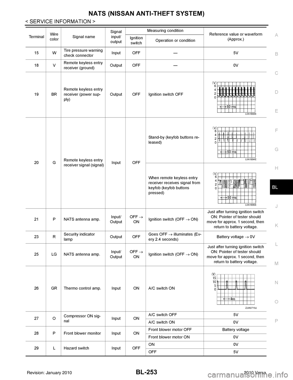
15 W Tire pressure warning
check connector
Input OFF
—5V
18 V Remote keyless entry
receiver (ground) Output OFF
—0V
19 BR Remote keyless entry
receiver (power sup-
ply) Output OFF Ignition switch OFF
20 G Remote keyless entry
receiver signal (signal)
Input OFFStand-by (keyfob buttons re-
leased)
When remote keyless entry
receiver receives signal from
keyfob (keyfob buttons
pressed)
21 P NATS antenna amp. Input/
Output OFF
→
ON Ignition switch (OFF → ON) Just after turning ignition switch
ON: Pointer of tester should
move for approx. 1 second, then
return to battery voltage.
23 R Security indicator
lamp Output OFF
Goes OFF
→ illuminates (Ev-
ery 2.4 seconds) Battery voltage
→ 0V
25 LG NATS antenna amp. Input/
Output OFF
→
ON Ignition switch (OFF → ON) Just after turning ignition switch
ON: Pointer of tester should
move for approx. 1 second, then return to battery voltage.
26 GR Thermo control amp. Input ON A/C switch ON
27 O Compressor ON sig-
nal Input ONA/C switch OFF
5V
A/C switch ON 0V
28 P Front blower monitor Input ON Front blower motor OFF
Battery voltage
Front blower motor ON 0V
29 L Hazard switch Input OFFON
0V
OFF 5V
Te r m i n a l
Wire
color Signal name Signal
input/
output Measuring condition
Reference value or waveform
(Approx.)
Ignition
switch Operation or condition
LIIA1893E
LIIA1894E
LIIA1895E
ZJIA0719J
Revision: January 20102010 Versa
Page 764 of 3745
NATS (NISSAN ANTI-THEFT SYSTEM)BL-255
< SERVICE INFORMATION >
C
DE
F
G H
J
K L
M A
B
BL
N
O P
435R Back door switch Input OFF ON (open) 0V
OFF (closed)
Battery voltage
44
5LG Rear wiper auto stop Input ON Rear wiper operating 0
Rear wiper stopped
Battery
45
7GR Lock switch Input OFFON (lock)
0V
OFF Battery voltage
46
7L Unlock switch Input OFFON (unlock)
0V
OFF Battery voltage
47 BR Front door switch LH Input OFF ON (open)
0V
OFF (closed) Battery voltage
48 O Rear door switch LH Input OFF ON (open)
0V
OFF (closed) Battery voltage
49 P Luggage room lamp Output OFF Any door open (ON)
0V
All doors closed (OFF) Battery voltage
50 SB A/C indicator Output ONA/C OFF
0
A/C ON Battery voltage
53
5R Back door lock assem-
bly (actuator)
Output OFF Back door (open)
Battery voltage
53
6R Trunk lamp switch and
trunk release solenoid Output OFF Trunk lid (open)
Battery voltage
55
5V Rear wiper motor out-
put
Output ONOFF
0
ON Battery voltage
56 R Battery saver output Output OFF
30 minutes after ignition
switch is turned OFF 0V
ON — Battery voltage
57 LG Battery power supply Input OFF —Battery voltage
59
7G Front door lock actua-
tor LH (unlock) Output OFFOFF (neutral)
0V
ON (unlock) Battery voltage
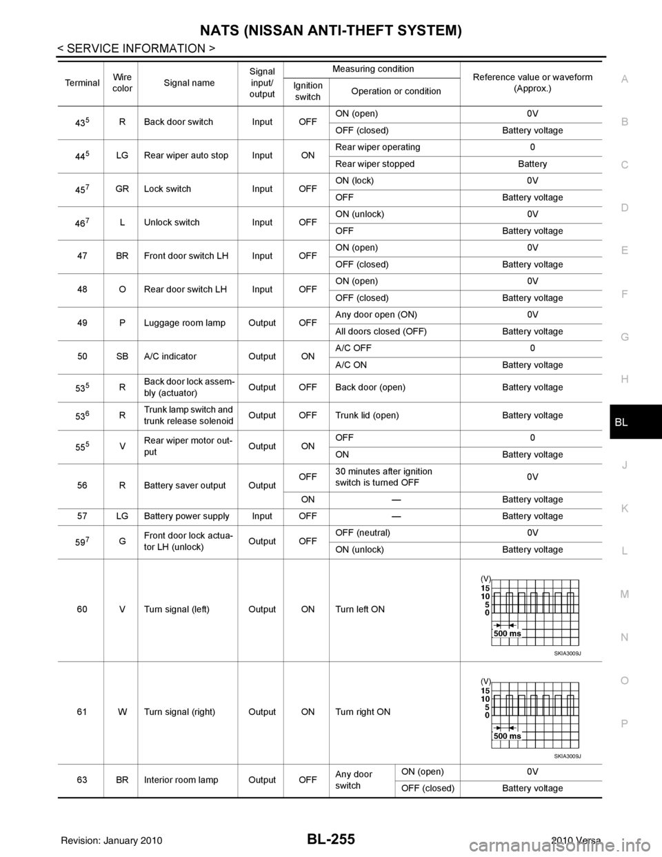
60 V Turn signal (left) Output ON Turn left ON
61 W Turn signal (right) Output ON Turn right ON
63 BR Interior room lamp Output OFF Any door
switchON (open)
0V
OFF (closed) Battery voltage
Te r m i n a l
Wire
color Signal name Signal
input/
output Measuring condition
Reference value or waveform
(Approx.)
Ignition
switch Operation or condition
SKIA3009J
SKIA3009J
Revision: January 20102010 Versa
Page 769 of 3745

BL-260
< SERVICE INFORMATION >
NATS (NISSAN ANTI-THEFT SYSTEM)
Self-diagnosis related item
• *: When NATS detects trouble, the security indicator lights up while ignition key is in the “ON” position.
SYMPTOM MATRIX CHART 2
Non self-diagnosis related item
*: CONSULT-III self-diagnostic results display screen “no malfunction is detected”.
Diagnosis Procedure 1INFOID:0000000005396711
Self-diagnostic results:
“CHAIN OF ECM-IMMU” displayed on CONSULT-III screen
First perform the “SELF-DIAG RESU LTS” in “BCM” with CONSULT-III, then perform the trouble diag-
nosis of malfunction system indicated “SELF-DIAG RESULTS” of “BCM”. Refer to BCS-18, "
CAN Com-
munication Inspection Using CONSULT-III (Self-Diagnosis)" .
SYMPTOMDisplayed “SELF-DIAG
RESULTS” on CON- SULT-III screen. DIAGNOSTIC PROCE-
DURE
(Reference page) SYSTEM
(Malfunctioning part or mode)
• Security indicator lighting up*
• Engine cannot be started CHAIN OF ECM-IMMU
[P1612] PROCEDURE 1
(BL-260
) In rare case, “CHAIN OF ECM-IMMU” might be stored
during key registration procedure, even if the system is
not malfunctioning.
Open circuit in battery voltage line of BCM circuit
Open circuit in ignition line of BCM circuit
Open circuit in ground line of BCM circuit
Open or short circuit between BCM and ECM commu-
nication line
ECM
BCM
DIFFERENCE OF KEY [P1615] PROCEDURE 6
(BL-266
) Unregistered ignition key is used.
BCM is malfunctioning.
CHAIN OF IMMU-KEY [P1614] PROCEDURE 2
(BL-262
) Malfunction of key ID chip
Communication line between ANT/ AMP and BCM:
Open circuit or short circuit of battery voltage line or
ground line
Open circuit in power source line of ANT/ AMP circuit
Open circuit in ground line of ANT/ AMP circuit
NATS antenna amp.
BCM
ID DISCORD, IMM- ECM
[P1611] PROCEDURE 3
(BL-263
) System initialization has not yet been completed.
ECM
LOCK MODE [P1610] PROCEDURE 5
(BL-265
) When the starting operation is carried out five or more
times consecutively under the following conditions,
NATS will shift the mode to one which prevents the en-
gine from being started.
• Unregistered ignition key is used.
• BCM or ECM’s malfunctioning.
Security indicator
lighting up* DON'T ERASE BE-
FORE CHECKING ENG DIAG WORK FLOW
(BL-257
) Engine trouble data and NATS trouble data have been
detected in ECM
SYMPTOM
DIAGNOSTIC PROCEDURE
(Reference page) SYSTEM
(Malfunctioning part or mode)
Security indicator does not light up*. PROCEDURE 4
(BL-264
) Security indictor.
Open circuit between Fuse and BCM
BCM
Revision: January 20102010 Versa
Page 774 of 3745
NATS (NISSAN ANTI-THEFT SYSTEM)BL-265
< SERVICE INFORMATION >
C
DE
F
G H
J
K L
M A
B
BL
N
O P
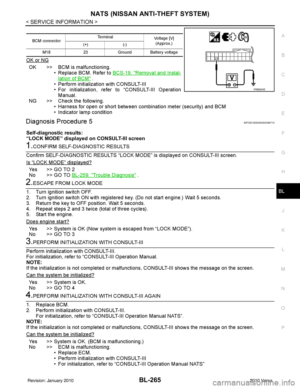
OK or NG
OK >> BCM is malfunctioning. • Replace BCM. Refer to BCS-19, "
Removal and Instal-
lation of BCM" .
• Perform initialization with CONSULT-III
• For initialization, refer to “CONSULT-III Operation Manual.
NG >> Check the following. • Harness for open or short between combination meter (security) and BCM
• Indicator lamp condition
Diagnosis Procedure 5INFOID:0000000005396715
Self-diagnostic results:
“LOCK MODE” displayed on CONSULT-III screen
1.CONFIRM SELF-DIAGNOSTIC RESULTS
Confirm SELF-DIAGNOSTIC RESULTS “LOCK MODE” is displayed on CONSULT-III screen.
Is
“LOCK MODE” displayed?
Yes >> GO TO 2
No >> GO TO BL-259, "
Trouble Diagnosis" .
2.ESCAPE FROM LOCK MODE
1. Turn ignition switch OFF.
2. Turn ignition switch ON with registered key. (Do not start engine.) Wait 5 seconds.
3. Return the key to OFF position. Wait 5 seconds.
4. Repeat steps 2 and 3 twice (total of three cycles).
5. Start the engine.
Does engine start?
Yes >> System is OK (Now system is escaped from “LOCK MODE”).
No >> GO TO 3
3.PERFORM INITIALIZATION WITH CONSULT-III
Perform initialization with CONSULT-III.
For initialization, refer to “CONSULT-III Operation Manual.
NOTE:
If the initialization is not completed or malf unctions, CONSULT-III shows the message on the screen.
Can the system be initialized?
Yes >> System is OK.
No >> GO TO 4
4.PERFORM INITIALIZATION WITH CONSULT-III AGAIN
1. Replace BCM.
2. Perform initialization with CONSULT-III. For initialization, refer to “CON SULT-III Operation Manual NATS”.
NOTE:
If the initialization is not completed or malf unctions, CONSULT-III shows the message on the screen.
Can the system be initialized?
Yes >> System is OK. (BCM is malfunctioning.)
No >> ECM is malfunctioning. • Replace ECM.
• Perform initialization with CONSULT-III
• For initialization, refer to “CONSULT-III Operation Manual NATS”
BCM connector Terminal
Voltage [V]
(Approx.)
(+) (-)
M18 23Ground Battery voltage
PIIB6594E
Revision: January 20102010 Versa
Page 871 of 3745
VACUUM LINESBR-23
< SERVICE INFORMATION >
C
DE
G H
I
J
K L
M A
B
BR
N
O P
VACUUM LINES
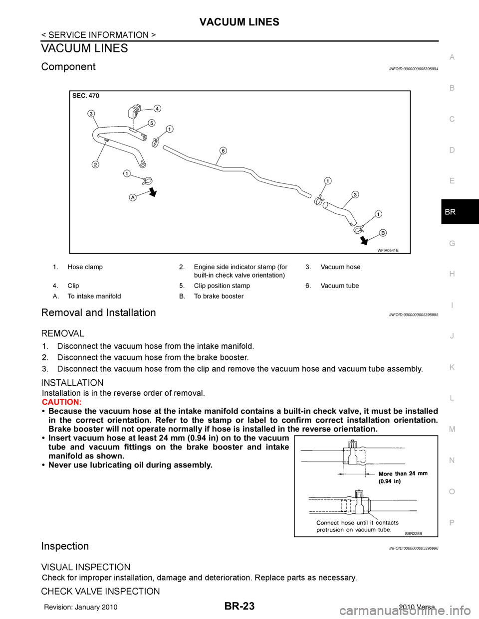
ComponentINFOID:0000000005396994
Removal and InstallationINFOID:0000000005396995
REMOVAL
1. Disconnect the vacuum hose from the intake manifold.
2. Disconnect the vacuum hose from the brake booster.
3. Disconnect the vacuum hose from the clip and re move the vacuum hose and vacuum tube assembly.
INSTALLATION
Installation is in the reverse order of removal.
CAUTION:
• Because the vacuum hose at the intake manifold contains a built-in check valve, it must be installed
in the correct orientation. Refer to the stamp or label to confirm correct installation orientation.
Brake booster will not operate normally if ho se is installed in the reverse orientation.
• Insert vacuum hose at least 24 mm (0.94 in) on to the vacuum tube and vacuum fittings on the brake booster and intake
manifold as shown.
• Never use lubricating oil during assembly.
InspectionINFOID:0000000005396996
VISUAL INSPECTION
Check for improper installation, damage and deterioration. Replace parts as necessary.
CHECK VALVE INSPECTION
1. Hose clamp 2. Engine side indicator stamp (for
built-in check valve orientation) 3. Vacuum hose
4. Clip 5. Clip position stamp6. Vacuum tube
A. To intake manifold B. To brake booster
WFIA0541E
SBR225B
Revision: January 20102010 Versa
Page 880 of 3745
BR-32
< SERVICE INFORMATION >
FRONT DISC BRAKE
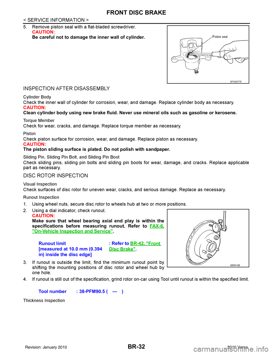
5. Remove piston seal with a flat-bladed screwdriver.CAUTION:
Be careful not to damage the inner wall of cylinder.
INSPECTION AFTER DISASSEMBLY
Cylinder Body
Check the inner wall of cylinder for corrosion, w ear, and damage. Replace cylinder body as necessary.
CAUTION:
Clean cylinder body using new brake fluid. Never use mineral oils such as gasoline or kerosene.
Torque Member
Check for wear, cracks, and damage. R eplace torque member as necessary.
Piston
Check piston surface for corrosion, wear, and damage. Replace piston as necessary.
CAUTION:
The piston sliding surface is plated. Do not polish with sandpaper.
Sliding Pin, Sliding Pin Bolt, and Sliding Pin Boot
Check sliding pins, sliding pin bolts and sliding pin boots for wear, damage, and cracks. Replace applicable
part as necessary.
DISC ROTOR INSPECTION
Visual Inspection
Check surfaces of disc rotor for uneven wear, cr acks, and serious damage. Replace as necessary.
Runout Inspection
1. Using wheel nuts, secure disc rotor to wheels hub at two or more positions.
2. Using a dial indicator, check runout.
CAUTION:
Make sure that wheel bearing axial end play is within the
specifications before measuring runout. Refer to FA X - 6 ,
"On-Vehicle Inspection and Service".
3. If runout is outside the limit, find the minimum runout point by shifting the mounting positions of disc rotor and wheel hub by
one hole.
4. If runout is still out of the specification, grind rotor on-car using Tool until runout is within the specified limit.
Thickness Inspection
SFIA2277E
Runout limit
[measured at 10.0 mm (0.394
in) inside the disc edge] : Refer to BR-42, "Front
Disc Brake".
Tool number : 38-PFM90.5 ( — )
SBR019B
Revision: January 20102010 Versa