Page 102 of 297
Downloaded from www.Manualslib.com manuals search engine jALHD models
jB RHD models
1. Pull the bonnet lock release lever
j1 , located
below the instrument panel on the driver’s side;
the bonnet will spring up slightly.
2. Slide the lever
j2 , at the front of the bonnet, with
your fingertips and raise the bonnet.
3. Insert the support rod
j3 into the slot on the
underside of the bonnet.
4. When closing the bonnet, replace the support rod in its original position, then slowly close the
bonnet and make sure it locks into place.
WARNING
Always check whether the bonnet is closed and
locked securely to prevent it from opening while
driving. The vehicle should only be operated with
the bonnet securely closed.
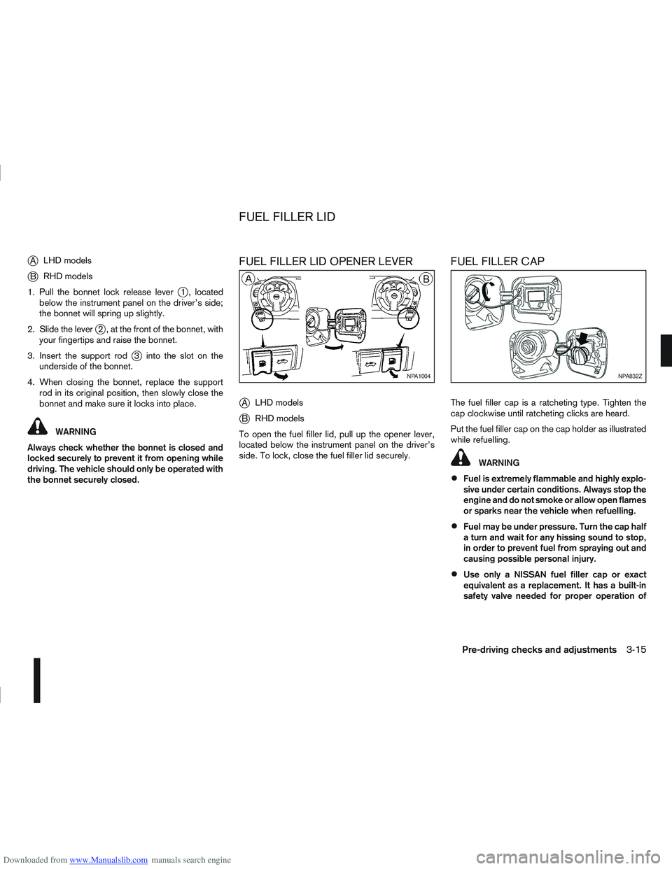
FUEL FILLER LID OPENER LEVER
j
A LHD models
jB RHD models
To open the fuel filler lid, pull up the opener lever,
located below the instrument panel on the driver’s
side. To lock, close the fuel filler lid securely.
FUEL FILLER CAP
The fuel filler cap is a ratcheting type. Tighten the
cap clockwise until ratcheting clicks are heard.
Put the fuel filler cap on the cap holder as illustrated
while refuelling.
WARNING
Fuel is extremely flammable and highly explo-
sive under certain conditions. Always stop the
engine and do not smoke or allow open flames
or sparks near the vehicle when refuelling.
Fuel may be under pressure. Turn the cap half
a turn and wait for any hissing sound to stop,
in order to prevent fuel from spraying out and
causing possible personal injury.
Use only a NISSAN fuel filler cap or exact
equivalent as a replacement. It has a built-in
safety valve needed for proper operation of
NPA1004NPA832Z
FUEL FILLER LID
Pre-driving checks and adjustments3-15
Page 103 of 297
Downloaded from www.Manualslib.com manuals search engine the fuel system and emission control system.
An incorrect cap can result in a serious mal-
function and possible injury.
CAUTION
If fuel is spilled on the vehicle body, flush it away
with water to avoid paint damage.
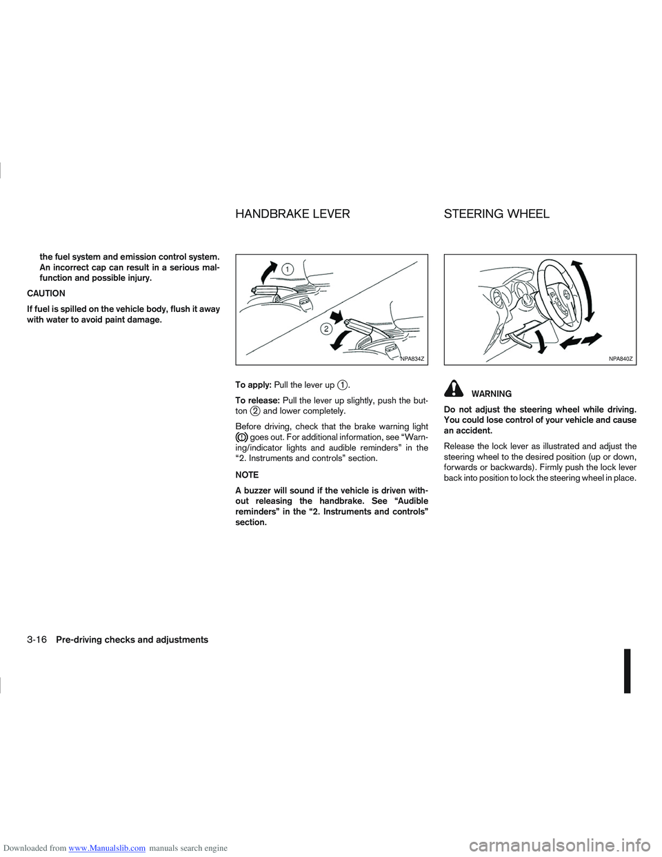
To apply:Pull the lever up
j1.
To release: Pull the lever up slightly, push the but-
ton
j2 and lower completely.
Before driving, check that the brake warning light
goes out. For additional information, see “Warn-
ing/indicator lights and audible reminders” in the
“2. Instruments and controls” section.
NOTE
A buzzer will sound if the vehicle is driven with-
out releasing the handbrake. See “Audible
reminders” in the “2. Instruments and controls”
section.
WARNING
Do not adjust the steering wheel while driving.
You could lose control of your vehicle and cause
an accident.
Release the lock lever as illustrated and adjust the
steering wheel to the desired position (up or down,
forwards or backwards). Firmly push the lock lever
back into position to lock the steering wheel in place.
NPA834ZNPA840Z
HANDBRAKE LEVER STEERING WHEEL
3-16Pre-driving checks and adjustments
Page 104 of 297

Downloaded from www.Manualslib.com manuals search engine CAUTION
Do not store the sun visor before returning it to
its original position.
1. To block out glare from the front, move the mainsun visor downwards.
2. To block glare from the side, remove the main sun visor from the centre mount and move it to
the side.
INSIDE REAR-VIEW MIRROR
j
1 Night position
j2Day position
jA Front of the vehicle
The night position
j1 will reduce glare from the
headlights of vehicles behind you at night.
WARNING
Only use the night position
j1 when necessary,
as it reduces rear-view clarity.
AUTOMATIC ANTI-DAZZLING INSIDE
MIRROR (where fitted)
The inside mirror is designed so that it automatically
adjusts the reflection according to the intensity of
the following vehicle’s headlights.
CAUTION
Do not hang any object on the mirror or spray
glass cleaner directly on the mirror. Doing so will
reduce the sensitivity of the sensor, resulting in
improper operation.
OUTSIDE REAR-VIEW MIRRORS
WARNING
Check the position of all mirrors before driv-
ing. Altering their position while driving could
distract your attention from the driving opera-
tion.
Objects viewed in the outside mirrors are
closer than they appear.
NPA839Z
NPA862Z
NPA829Z
SUN VISORS MIRRORS
Pre-driving checks and adjustments3-17
Page 105 of 297
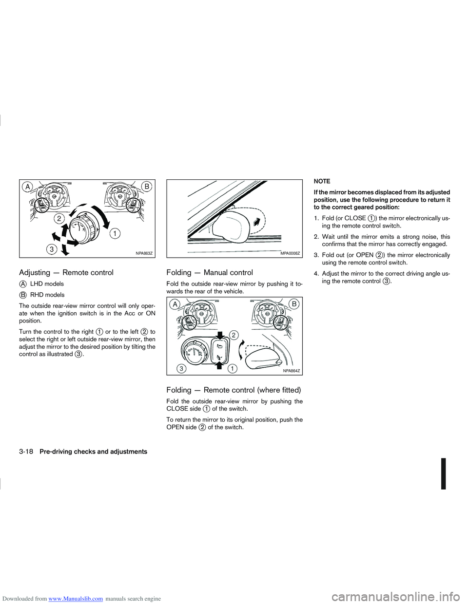
Downloaded from www.Manualslib.com manuals search engine Adjusting — Remote control
j
ALHD models
jB RHD models
The outside rear-view mirror control will only oper-
ate when the ignition switch is in the Acc or ON
position.
Turn the control to the right
j1 ortotheleftj2to
select the right or left outside rear-view mirror, then
adjust the mirror to the desired position by tilting the
control as illustrated
j3.
Folding — Manual control
Fold the outside rear-view mirror by pushing it to-
wards the rear of the vehicle.
Folding — Remote control (where fitted)
Fold the outside rear-view mirror by pushing the
CLOSE sidej1 of the switch.
To return the mirror to its original position, push the
OPEN side
j2 of the switch. NOTE
If the mirror becomes displaced from its adjusted
position, use the following procedure to return it
to the correct geared position:
1. Fold (or CLOSE
j1 ) the mirror electronically us-
ing the remote control switch.
2. Wait until the mirror emits a strong noise, this confirms that the mirror has correctly engaged.
3. Fold out (or OPEN
j2 ) the mirror electronically
using the remote control switch.
4. Adjust the mirror to the correct driving angle us- ing the remote control
j3.
NPA863ZMPA0008Z
NPA864Z
3-18Pre-driving checks and adjustments
Page 106 of 297
Downloaded from www.Manualslib.com manuals search engine VANITY MIRROR
To use the front vanity mirror, pull down the sun
visor and lift up the cover.
NPA842Z
Left hand drive
NPA910Z
Right hand drive
Pre-driving checks and adjustments3-19
Page 107 of 297
Downloaded from www.Manualslib.com manuals search engine NOTE
3-20Pre-driving checks and adjustments
Page 109 of 297
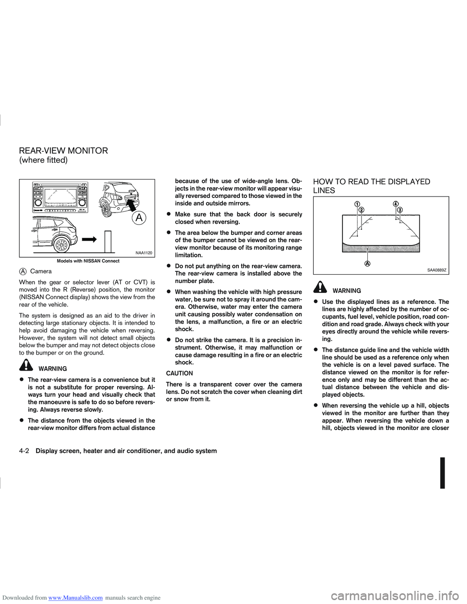
Downloaded from www.Manualslib.com manuals search engine jACamera
When the gear or selector lever (AT or CVT) is
moved into the R (Reverse) position, the monitor
(NISSAN Connect display) shows the view from the
rear of the vehicle.
The system is designed as an aid to the driver in
detecting large stationary objects. It is intended to
help avoid damaging the vehicle when reversing.
However, the system will not detect small objects
below the bumper and may not detect objects close
to the bumper or on the ground.
WARNING
The rear-view camera is a convenience but it
is not a substitute for proper reversing. Al-
ways turn your head and visually check that
the manoeuvre is safe to do so before revers-
ing. Always reverse slowly.
The distance from the objects viewed in the
rear-view monitor differs from actual distance because of the use of wide-angle lens. Ob-
jects in the rear-view monitor will appear visu-
ally reversed compared to those viewed in the
inside and outside mirrors.
Make sure that the back door is securely
closed when reversing.
The area below the bumper and corner areas
of the bumper cannot be viewed on the rear-
view monitor because of its monitoring range
limitation.
Do not put anything on the rear-view camera.
The rear-view camera is installed above the
number plate.
When washing the vehicle with high pressure
water, be sure not to spray it around the cam-
era. Otherwise, water may enter the camera
unit causing possibly water condensation on
the lens, a malfunction, a fire or an electric
shock.
Do not strike the camera. It is a precision in-
strument. Otherwise, it may malfunction or
cause damage resulting in a fire or an electric
shock.
CAUTION
There is a transparent cover over the camera
lens. Do not scratch the cover when cleaning dirt
or snow from it.
HOW TO READ THE DISPLAYED
LINES
WARNING
Use the displayed lines as a reference. The
lines are highly affected by the number of oc-
cupants, fuel level, vehicle position, road con-
dition and road grade. Always check with your
eyes directly around the vehicle while revers-
ing.
The distance guide line and the vehicle width
line should be used as a reference only when
the vehicle is on a level paved surface. The
distance viewed on the monitor is for refer-
ence only and may be different than the ac-
tual distance between the vehicle and dis-
played objects.
When reversing the vehicle up a hill, objects
viewed in the monitor are further than they
appear. When reversing the vehicle down a
hill, objects viewed in the monitor are closer
NAA1120
Models with NISSAN Connect
SAA0889Z
REAR-VIEW MONITOR
(where fitted)
4-2Display screen, heater and air conditioner, and audio system
Page 111 of 297
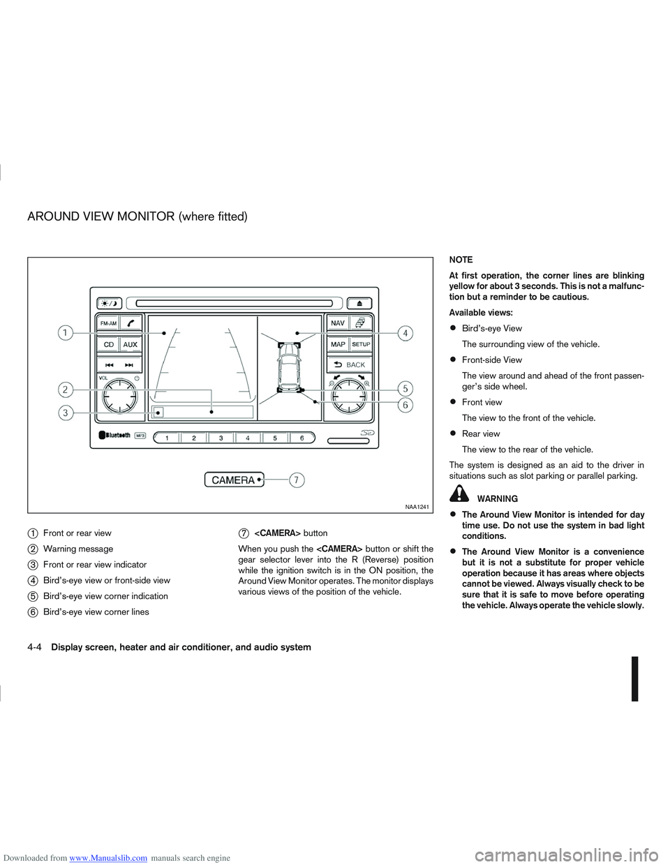
Downloaded from www.Manualslib.com manuals search engine j1Front or rear view
j2Warning message
j3Front or rear view indicator
j4Bird’s-eye view or front-side view
j5Bird’s-eye view corner indication
j6Bird’s-eye view corner lines
j7
button
When you push the button or shift the
gear selector lever into the R (Reverse) position
while the ignition switch is in the ON position, the
Around View Monitor operates. The monitor displays
various views of the position of the vehicle. NOTE
At first operation, the corner lines are blinking
yellow for about 3 seconds. This is not a malfunc-
tion but a reminder to be cautious.
Available views:
Bird’s-eye View
The surrounding view of the vehicle.
Front-side View
The view around and ahead of the front passen-
ger’s side wheel.
Front view
The view to the front of the vehicle.
Rear view
The view to the rear of the vehicle.
The system is designed as an aid to the driver in
situations such as slot parking or parallel parking.
WARNING
The Around View Monitor is intended for day
time use. Do not use the system in bad light
conditions.
The Around View Monitor is a convenience
but it is not a substitute for proper vehicle
operation because it has areas where objects
cannot be viewed. Always visually check to be
sure that it is safe to move before operating
the vehicle. Always operate the vehicle slowly.
NAA1241
AROUND VIEW MONITOR (where fitted)
4-4Display screen, heater and air conditioner, and audio system