Page 1225 of 3745

COMBINATION METERSDI-15
< SERVICE INFORMATION >
C
DE
F
G H
I
J
L
M A
B
DI
N
O P
YES >> GO TO 2.
NO >> Check power supply and ground circuit of combination meter. Refer to DI-15, "
Power Supply and
Ground Circuit Inspection" .
2.CHECK COMBINATION METER (CONSULT-III)
Select “METER/M&A” on CONSULT-II I and perform self-diagnosis of combination meter. Refer to DI-13,
"CONSULT-III Function (METER/M&A)" .
Self
-diagnostic results content
No malfunction detected>> Refer to DI-15, "Symptom Chart" .
Malfunction detected>> Refer to DI-13, "
CONSULT-III Function (METER/M&A)" .
Symptom ChartINFOID:0000000005395017
Power Supply and Gro und Circuit InspectionINFOID:0000000005395018
1.CHECK FUSE
Check for blown combination meter fuses.
OK or NG
OK >> GO TO 2.
NG >> Be sure to eliminate cause of malfunction before installing new fuse. Refer to PG-4
.
2.CHECK POWER SUPPLY CIRCUIT
Check voltage between combination meter harness connector termi-
nals and ground.
OK or NG
OK >> GO TO 3.
NG >> Repair harness or connector.
3.CHECK GROUND CIRCUIT
1. Turn ignition switch OFF.
2. Disconnect combination meter connector.
Symptom Possible cause
Improper speedometer and odo/trip meter indication. Refer to DI-16, "
Vehicle Speed Signal Inspection" .
Improper tachometer indication. Refer to DI-17, "
Engine Speed Signal Inspection" .
Improper fuel gauge indication. Refer to DI-17, "
Fuel Level Sensor Signal Inspection" .
Low-fuel warning lamp indication is irregular.
Improper A/T position indication. Refer to DI-36, "
A/T Indicator Does Not Illuminate" .
Improper CVT position indication. Refer to DI-41, "
CVT Indicator Does Not Illuminate" .
Power source Fuse No.
Battery 13
Ignition switch ON or START 3
TerminalsIgnition switch position
(+) (–) OFF ON
Combination meter
connector Te r m i n a l
M24 27
Ground Battery voltage Battery voltage
28 0 V Battery voltage
PKIC0700E
Revision: January 20102010 Versa
Page 1253 of 3745
WARNING CHIMEDI-43
< SERVICE INFORMATION >
C
DE
F
G H
I
J
L
M A
B
DI
N
O P
WARNING CHIME
Component Parts and Har ness Connector LocationINFOID:0000000005395039
System DescriptionINFOID:0000000005395040
• Buzzer for warning chime system is installed in the combination meter.
• The buzzer sounds when combination meter receives buzzer output signal with CAN communication line.
POWER SUPPLY AND GROUND CIRCUIT
Power is supplied at all times
• through 40A fusible link (letter g, located in the fuse and fusible link box)
• to BCM terminal 70,
1. Combination meter M24 2. BCM M18, M19, M20 (view with
glove box removed) 3. Intelligent Key unit M52 (with Intelli-
gent Key)
4. Key switch and key lock solenoid M27 (without Intelligent Key) 5. Key switch and ignition knob switch
M73 (with Intelligent Key) 6. Combination switch (lighting switch)
M28
7. Front door switch LH B8 8. Parking brake switch M17
AWMIA0117ZZ
Revision: January 20102010 Versa
Page 1254 of 3745
![NISSAN LATIO 2010 Service Repair Manual DI-44
< SERVICE INFORMATION >
WARNING CHIME
• through 10A fuse [No. 8, located in the fuse block (J/B)]
• to BCM terminal 57,
• through 10A fuse [No. 13, located in the fuse block (J/B)]
• to NISSAN LATIO 2010 Service Repair Manual DI-44
< SERVICE INFORMATION >
WARNING CHIME
• through 10A fuse [No. 8, located in the fuse block (J/B)]
• to BCM terminal 57,
• through 10A fuse [No. 13, located in the fuse block (J/B)]
• to](/manual-img/5/57358/w960_57358-1253.png)
DI-44
< SERVICE INFORMATION >
WARNING CHIME
• through 10A fuse [No. 8, located in the fuse block (J/B)]
• to BCM terminal 57,
• through 10A fuse [No. 13, located in the fuse block (J/B)]
• to combination meter terminal 27.
With ignition switch in the ON or START position, power is supplied
• through 10A fuse [No. 6, located in the fuse block (J/B)]
• to BCM terminal 38,
• through 10A fuse [No. 3, located in the fuse block (J/B)]
• to combination meter terminal 28.
Ground is supplied
• to BCM terminal 67 and
• to combination meter terminals 21, 22 and 23
• through grounds M57 and M61.
IGNITION KEY WARNING CHIME (WITHOUT INTELLIGENT KEY)
With the key inserted into the key switch, and the ignition switch in the OFF or ACC position, when driver's
door is opened, the warning chime will sound.
• BCM detects key inserted into the ignition switch, and sends key warning signal to combination meter with CAN communication line.
• When combination meter receives key warning signal, it sounds warning chime.
IGNITION KEY WARNING CHIME (WITH INTELLIGENT KEY)
When Mechanical Key Is Used
With the key inserted into the key switch, and the igniti on switch in the LOCK or ACC position, when driver's
door is opened, the warning chime will sound.
• BCM detects key inserted into the ignition switch, and sends key warning signal to combination meter with
CAN communication line.
• When combination meter receives key warning signal, it sounds warning chime.
When Intelligent Key Is Carried With The Driver
Refer to BL-88, "System Description".
LIGHT WARNING CHIME
The warning chime sounds, when driver's door is opened (door switch ON) with lighting switch ON and the
ignition switch is in any position other than ON or START.
NOTE:
BCM detected lighting switch in the 1st or 2nd position, refer to LT-65, "
Combination Switch Reading Func-
tion".
• BCM detects headlamps are illuminated, and sends light warning signal to combination meter with CAN
communication lines.
WKIA5463E
WKIA5464E
Revision: January 20102010 Versa
Page 1261 of 3745

WARNING CHIMEDI-51
< SERVICE INFORMATION >
C
DE
F
G H
I
J
L
M A
B
DI
N
O P
OK >> Replace BCM. Refer to BCS-19, "Removal and Installation of BCM".
NG >> Replace front door switch LH.
Key Switch Signal Inspection (Without Intelligent Key)INFOID:0000000005395047
1.CHECK FUSE
Check if the key switch and key lock solenoid 10A fuse [No. 14, located in the fuse block (J/B)] is blown.
OK or NG
OK >> GO TO 2.
NG >> Be sure to repair the cause of malfunction before installing new fuse. Refer to PG-4
.
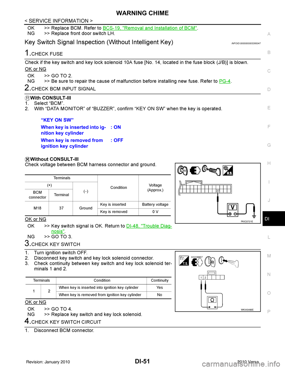
2.CHECK BCM INPUT SIGNAL
With CONSULT-III
1. Select “BCM”.
2. With “DATA MONITOR” of “BUZZER”, confirm “KEY ON SW” when the key is operated.
Without CONSULT-III
Check voltage between BCM harness connector and ground.
OK or NG
OK >> Key switch signal is OK. Return to DI-48, "Trouble Diag-
nosis".
NG >> GO TO 3.
3.CHECK KEY SWITCH
1. Turn ignition switch OFF.
2. Disconnect key switch and key lock solenoid connector.
3. Check continuity between key switch and key lock solenoid ter- minals 1 and 2.
OK or NG
OK >> GO TO 4.
NG >> Replace key switch and key lock solenoid.
4.CHECK KEY SWITCH CIRCUIT
1. Disconnect BCM connector. “KEY ON SW”
When key is inserted into ig-
nition key cylinder
: ON
When key is removed from
ignition key cylinder : OFF
Te r m i n a l s
ConditionVoltag e
(Approx.)
(+)
(−)
BCM
connector Te r m i n a l
M18 37 Ground Key is inserted Battery voltage
Key is removed
0 V
PKIC0721E
Terminals ConditionContinuity
12 When key is inserted into ignition key cylinder Yes
When key is removed from ignition key cylinder No
WKIA5466E
Revision: January 20102010 Versa
Page 1262 of 3745

DI-52
< SERVICE INFORMATION >
WARNING CHIME
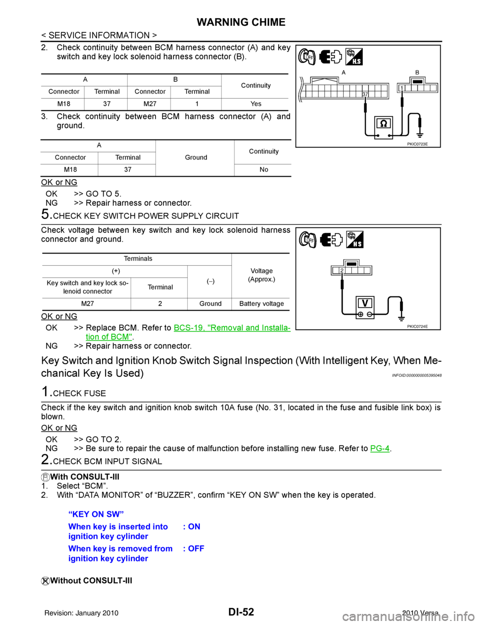
2. Check continuity between BCM harness connector (A) and keyswitch and key lock solenoid harness connector (B).
3. Check continuity between BCM harness connector (A) and ground.
OK or NG
OK >> GO TO 5.
NG >> Repair harness or connector.
5.CHECK KEY SWITCH PO WER SUPPLY CIRCUIT
Check voltage between key switch and key lock solenoid harness
connector and ground.
OK or NG
OK >> Replace BCM. Refer to BCS-19, "Removal and Installa-
tion of BCM".
NG >> Repair harness or connector.
Key Switch and Ignition Knob Switch Signal Inspection (With Intelligent Key, When Me-
chanical Key Is Used)
INFOID:0000000005395048
1.CHECK FUSE
Check if the key switch and ignition knob switch 10A fuse (No. 31, located in the fuse and fusible link box) is
blown.
OK or NG
OK >> GO TO 2.
NG >> Be sure to repair the cause of malfunction before installing new fuse. Refer to PG-4
.
2.CHECK BCM INPUT SIGNAL
With CONSULT-III
1. Select “BCM”.
2. With “DATA MONITOR” of “BUZZER”, c onfirm “KEY ON SW” when the key is operated.
Without CONSULT-III
AB Continuity
Connector Terminal Connector Terminal
M18 37 M27 1Yes
A GroundContinuity
Connector Terminal
M18 37 No
PKIC0723E
Te r m i n a l s
Voltage
(Approx.)
(+)
(−)
Key switch and key lock so-
lenoid connector Te r m i n a l
M27 2Ground Battery voltage
PKIC0724E
“KEY ON SW”
When key is inserted into
ignition key cylinder : ON
When key is removed from
ignition key cylinder : OFF
Revision: January 20102010 Versa
Page 1297 of 3745
EC-32
< FUNCTION DIAGNOSIS >[HR16DE]
ENGINE CONTROL SYSTEM
1. ECM harness connectors
2. ECM 3. IPDM E/R
4. Fuel pump fuse (15A) 5. Intake valve timing control solenoid
valve 6. Knock sensor
7. Refrigerant pressure sensor 8. PCV valve Vehicle front
PBIB2941E
Revision: January 20102010 Versa
Page 1306 of 3745
MULTIPORT FUEL INJECTION SYSTEMEC-41
< FUNCTION DIAGNOSIS > [HR16DE]
C
D
E
F
G H
I
J
K L
M A
EC
NP
O
1. ECM harness connectors
2. ECM3. IPDM E/R
4. Fuel pump fuse (15A) 5. Intake valve timing control solenoid
valve 6. Knock sensor
7. Refrigerant pressure sensor 8. PCV valve Vehicle front
PBIB2941E
Revision: January 20102010 Versa
Page 1313 of 3745
EC-48
< FUNCTION DIAGNOSIS >[HR16DE]
ELECTRIC IGNITION SYSTEM
1. ECM harness connectors
2. ECM 3. IPDM E/R
4. Fuel pump fuse (15A) 5. Intake valve timing control solenoid
valve 6. Knock sensor
7. Refrigerant pressure sensor 8. PCV valve Vehicle front
PBIB2941E
Revision: January 20102010 Versa