2010 NISSAN LATIO fuse
[x] Cancel search: fusePage 715 of 3745

BL-206
< SERVICE INFORMATION >
TRUNK LID OPENER
Data Monitor
Active Test
Work FlowINFOID:0000000005396674
1. Check the symptom and customer's requests.
2. Understand the outline of system. Refer to BL-196, "
System Description".
3. Repair or replace any malfunctioning parts. Refer to BL-206, "
Trouble Diagnosis Chart by Symptom".
4. Does trunk lid opener operate normally? If Yes, GO TO 5. If No, GO TO 3.
5. Inspection End.
Trouble Diagnosis Chart by SymptomINFOID:0000000005396675
BCM Power Supply and Ground Circuit InspectionINFOID:0000000005612421
1.CHECK FUSES AND FUSIBLE LINK
• Check 40A fusible link (letter g , located in the fuse and fusible link box).
• Check 10A fuses [No. 6, 8 and 20, lo cated in the fuse block (J/B)].
OK or NG
OK >> GO TO 2.
NG >> If fuse is blown, be sure to eliminate cause of malfunction before installing new fuse. Refer to PG-
4, "Schematic" .
Monitor itemContent
IGN ON SW Indicates [ON/OFF] condition of ignition switch.
TRNK OPNR SW Indicates [ON/OFF] condition of trun k open signal from trunk lid opener switch.
VEHICLE SPEED Indicates [km/h] condition of vehicle speed.
Test item Content
TRUNK/BACK DOOR This test is able to check trunk lid lock assembly (actuator) unlock operation.
Actuator opens trunk lid lock assembly when “OPEN” on CONSULT-III screen is touched.
Symptom
Diagnoses/service procedureReference
page
Trunk lid opener does not operate.
(Without Intelligent Key or power windows) 1. Check BCM power supply and ground circuit.
BCS-16
2. Check trunk lid opener switch circuit. BL-207
3. Check trunk lid lock assembly (actuator) circuit.BL-214
4. Replace BCM.BCS-19
Trunk lid opener does not operate.
(Without Intelligent Key, with power windows)1. Check BCM power supply and ground circuit.
BCS-162. Check trunk lid opener switch circuit. BL-210
3. Check trunk lid lock assembly (actuator) circuit.BL-214
4. Replace BCM.BCS-19
Trunk lid opener does not operate.
(With Intelligent Key)1. Check BCM power supply and ground circuit.
BCS-16
2.Check Intelligent Key power supply and ground cir-
cuit. BL-126
3. Check trunk lid opener switch circuit.
BL-212
4. Check trunk lid lock assembly (actuator) circuit.BL-214
5. Replace BCM.BCS-19
Revision: January 20102010 Versa
Page 728 of 3745
VEHICLE SECURITY (THEFT WARNING) SYSTEMBL-219
< SERVICE INFORMATION >
C
DE
F
G H
J
K L
M A
B
BL
N
O P
System DescriptionINFOID:0000000005396683
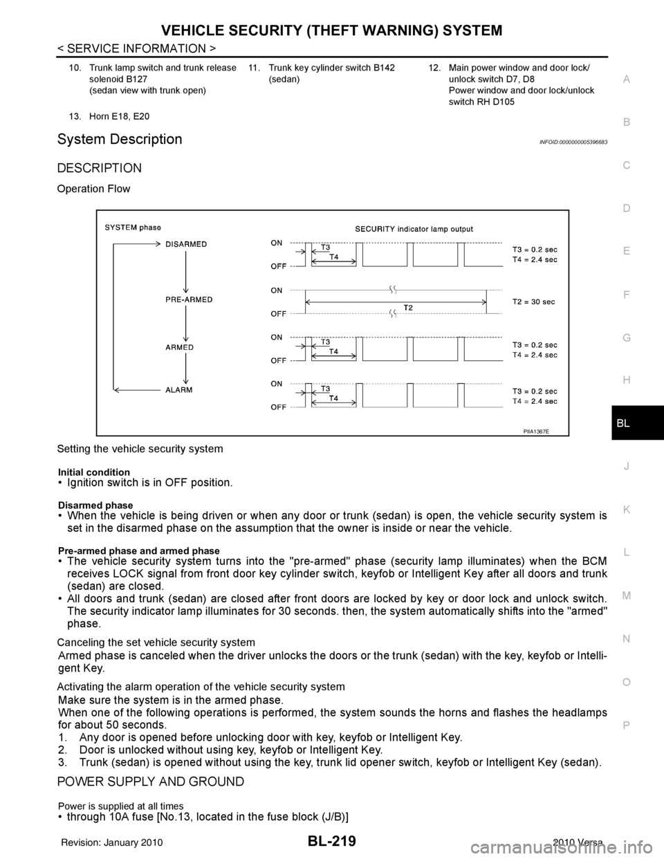
DESCRIPTION
Operation Flow
Setting the vehicle security system
Initial condition• Ignition switch is in OFF position.
Disarmed phase• When the vehicle is being driven or when any door or trunk (sedan) is open, the vehicle security system is set in the disarmed phase on the assumption that the owner is inside or near the vehicle.
Pre-armed phase and armed phase• The vehicle security system turns into the "pre- armed" phase (security lamp illuminates) when the BCM
receives LOCK signal from front door key cylinder s witch, keyfob or Intelligent Key after all doors and trunk
(sedan) are closed.
• All doors and trunk (sedan) are closed after front doors are locked by key or door lock and unlock switch.
The security indicator lamp illuminates for 30 seconds. t hen, the system automatically shifts into the "armed"
phase.
Canceling the set vehicle security system
Armed phase is canceled when the driver unlocks the doors or the trunk (sedan) with the key, keyfob or Intelli-
gent Key.
Activating the alarm operation of the vehicle security system
Make sure the system is in the armed phase.
When one of the following operations is performed, the system sounds the horns and flashes the headlamps
for about 50 seconds.
1. Any door is opened before unlocking door with key, keyfob or Intelligent Key.
2. Door is unlocked without using key, keyfob or Intelligent Key.
3. Trunk (sedan) is opened without using the key, trunk lid opener switch, keyfob or Intelligent Key (sedan).
POWER SUPPLY AND GROUND
Power is supplied at all times• through 10A fuse [No.13, located in the fuse block (J/B)]
10. Trunk lamp switch and trunk release
solenoid B127
(sedan view with trunk open) 11. Trunk key cylinder switch B142
(sedan) 12. Main power window and door lock/
unlock switch D7, D8
Power window and door lock/unlock
switch RH D105
13. Horn E18, E20
PIIA1367E
Revision: January 20102010 Versa
Page 729 of 3745

BL-220
< SERVICE INFORMATION >
VEHICLE SECURITY (THEFT WARNING) SYSTEM
• to combination meter terminal 27 (security indicator lamp)
• through 40A fusible link (letter g, located in the fuse and fusible link box)
• to BCM terminal 70
• through 10A fuse [No. 8, located in the fuse block (J/B)]
• to BCM terminal 57
• through 10A fuse (No. 28, located in the fuse and fusible link box)
• to horn relay terminal 2
• through 15A fuse (No. 52, located in the IPDM E/R)
• to IPDM E/R internal CPU.
• through 20A fuse (No. 53, located in the IPDM E/R)
• to IPDM E/R internal CPU.
With the ignition switch in the ACC or ON position, power is supplied• through 10A fuse [No. 20, located in the fuse block (J/B)]
• to BCM terminal 11.
With the ignition switch in the ON or START po sition, power is supplied• through 10A fuse [No. 6, located in the fuse block (J/B)]
• to BCM terminal 38.
Ground is supplied• to BCM terminal 67
• through body grounds M57 and M61.
INITIAL CONDITION TO ACTIVATE THE SYSTEM
The operation of the vehicle security system is controlled by the doors and trunk (sedan).
To activate the vehicle security system, BCM must receive signals indicating the ignition switch is OFF, doors
and trunk (sedan) are closed and locked.
When a door or trunk (sedan) is open, BCM terminal 12, 13, 42, 43, 47 or 48 receives a ground signal from
each door or trunk switch. In addition to BCM, when back door is open, the Intelligent Key unit terminal 23
receives a ground signal from back door or trunk (sedan) through BCM terminal 30.
When front door LH is unlocked, BCM terminal 46 receives a signal from terminal 6 of main power window and
door lock/unlock switch.
When front door RH is unlocked, BCM terminal 46 receives a signal from terminal 2 of power window and door
lock/unlock switch RH.
VEHICLE SECURITY SYSTEM ALARM OPERATION
The vehicle security system is triggered by
• Opening a door without using the key, keyfob or Intelligent Key.
• Opening trunk without using the key, keyfob or Intelligent Key (sedan).
The vehicle security system will be tri ggered once the system is in armed phase,
• when BCM receives a ground signal at terminals 12, 13, 47, 48 (front or rear door switch), terminal 42
(sedan, trunk switch) or terminal 43 (hatchback, back door switch).
When the vehicle security system is triggered, ground is supplied intermittently
• from IPDM E/R terminal 45
• to horn relay terminal 1.
The headlamps flash and the horn sounds intermittently.
The alarm automatically turns off after 50 seconds, but will reactivate if the vehicle is tampered with again.
VEHICLE SECURITY SYSTEM DEACTIVATION
To deactivate the vehicle security system, a door or trunk (sedan) must be unlocked with the key, keyfob or
Intelligent Key.
When the key is used to unlock the driver door, BCM terminal 7 receives signal
• from terminal 3 of the front door key cylinder switch LH.
When the key is used to open the trunk (sedan), BCM terminal 41 receives signal
• from terminal 1 of the trunk key cylinder switch.
When the BCM receives an unlock signal from keyfob, In telligent Key, front door key cylinder switch LH or
trunk key cylinder switch (sedan), the vehicle se curity system is deactivated (Disarmed phase).
PANIC ALARM OPERATION
Intelligent Key and remote keyless entry system may or may not operate vehicle security system (horn and
headlamps) as required.
When the vehicle security system is triggered, ground is supplied intermittently
Revision: January 20102010 Versa
Page 751 of 3745
BL-242
< SERVICE INFORMATION >
VEHICLE SECURITY (THEFT WARNING) SYSTEM
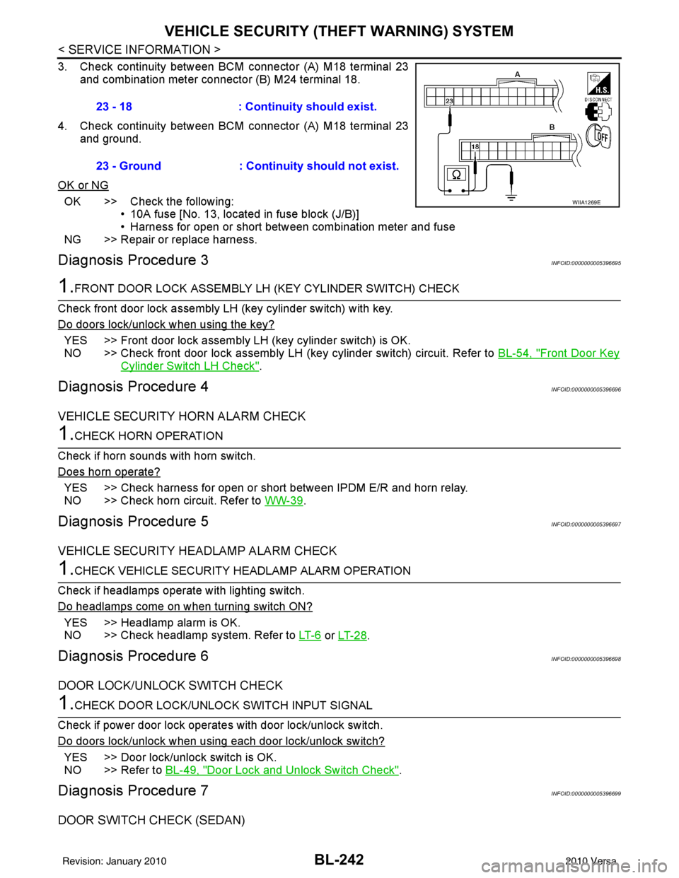
3. Check continuity between BCM connector (A) M18 terminal 23
and combination meter connector (B) M24 terminal 18.
4. Check continuity between BCM connector (A) M18 terminal 23 and ground.
OK or NG
OK >> Check the following: • 10A fuse [No. 13, located in fuse block (J/B)]
• Harness for open or short between combination meter and fuse
NG >> Repair or replace harness.
Diagnosis Procedure 3INFOID:0000000005396695
1.FRONT DOOR LOCK ASSEMBLY LH (KEY CYLINDER SWITCH) CHECK
Check front door lock assembly LH (key cylinder switch) with key.
Do doors lock/unlock when using the key?
YES >> Front door lock assembly LH (key cylinder switch) is OK.
NO >> Check front door lock assembly LH (key cylinder switch) circuit. Refer to BL-54, "
Front Door Key
Cylinder Switch LH Check".
Diagnosis Procedure 4INFOID:0000000005396696
VEHICLE SECURITY HORN ALARM CHECK
1.CHECK HORN OPERATION
Check if horn sounds with horn switch.
Does horn operate?
YES >> Check harness for open or short between IPDM E/R and horn relay.
NO >> Check horn circuit. Refer to WW-39
.
Diagnosis Procedure 5INFOID:0000000005396697
VEHICLE SECURITY HEADLAMP ALARM CHECK
1.CHECK VEHICLE SECURITY HEADLAMP ALARM OPERATION
Check if headlamps operate with lighting switch.
Do headlamps come on when turning switch ON?
YES >> Headlamp alarm is OK.
NO >> Check headlamp system. Refer to LT- 6
or LT- 2 8.
Diagnosis Procedure 6INFOID:0000000005396698
DOOR LOCK/UNLOCK SWITCH CHECK
1.CHECK DOOR LOCK/UNLOCK SWITCH INPUT SIGNAL
Check if power door lock operates with door lock/unlock switch.
Do doors lock/unlock when using each door lock/unlock switch?
YES >> Door lock/unlock switch is OK.
NO >> Refer to BL-49, "
Door Lock and Unlock Switch Check".
Diagnosis Procedure 7INFOID:0000000005396699
DOOR SWITCH CHECK (SEDAN)
23 - 18 : Continuity should exist.
23 - Ground : Continuity should not exist.
WIIA1269E
Revision: January 20102010 Versa
Page 769 of 3745

BL-260
< SERVICE INFORMATION >
NATS (NISSAN ANTI-THEFT SYSTEM)
Self-diagnosis related item
• *: When NATS detects trouble, the security indicator lights up while ignition key is in the “ON” position.
SYMPTOM MATRIX CHART 2
Non self-diagnosis related item
*: CONSULT-III self-diagnostic results display screen “no malfunction is detected”.
Diagnosis Procedure 1INFOID:0000000005396711
Self-diagnostic results:
“CHAIN OF ECM-IMMU” displayed on CONSULT-III screen
First perform the “SELF-DIAG RESU LTS” in “BCM” with CONSULT-III, then perform the trouble diag-
nosis of malfunction system indicated “SELF-DIAG RESULTS” of “BCM”. Refer to BCS-18, "
CAN Com-
munication Inspection Using CONSULT-III (Self-Diagnosis)" .
SYMPTOMDisplayed “SELF-DIAG
RESULTS” on CON- SULT-III screen. DIAGNOSTIC PROCE-
DURE
(Reference page) SYSTEM
(Malfunctioning part or mode)
• Security indicator lighting up*
• Engine cannot be started CHAIN OF ECM-IMMU
[P1612] PROCEDURE 1
(BL-260
) In rare case, “CHAIN OF ECM-IMMU” might be stored
during key registration procedure, even if the system is
not malfunctioning.
Open circuit in battery voltage line of BCM circuit
Open circuit in ignition line of BCM circuit
Open circuit in ground line of BCM circuit
Open or short circuit between BCM and ECM commu-
nication line
ECM
BCM
DIFFERENCE OF KEY [P1615] PROCEDURE 6
(BL-266
) Unregistered ignition key is used.
BCM is malfunctioning.
CHAIN OF IMMU-KEY [P1614] PROCEDURE 2
(BL-262
) Malfunction of key ID chip
Communication line between ANT/ AMP and BCM:
Open circuit or short circuit of battery voltage line or
ground line
Open circuit in power source line of ANT/ AMP circuit
Open circuit in ground line of ANT/ AMP circuit
NATS antenna amp.
BCM
ID DISCORD, IMM- ECM
[P1611] PROCEDURE 3
(BL-263
) System initialization has not yet been completed.
ECM
LOCK MODE [P1610] PROCEDURE 5
(BL-265
) When the starting operation is carried out five or more
times consecutively under the following conditions,
NATS will shift the mode to one which prevents the en-
gine from being started.
• Unregistered ignition key is used.
• BCM or ECM’s malfunctioning.
Security indicator
lighting up* DON'T ERASE BE-
FORE CHECKING ENG DIAG WORK FLOW
(BL-257
) Engine trouble data and NATS trouble data have been
detected in ECM
SYMPTOM
DIAGNOSTIC PROCEDURE
(Reference page) SYSTEM
(Malfunctioning part or mode)
Security indicator does not light up*. PROCEDURE 4
(BL-264
) Security indictor.
Open circuit between Fuse and BCM
BCM
Revision: January 20102010 Versa
Page 770 of 3745
NATS (NISSAN ANTI-THEFT SYSTEM)BL-261
< SERVICE INFORMATION >
C
DE
F
G H
J
K L
M A
B
BL
N
O P
1.CONFIRM SELF-DIAGNOSTIC RESULTS
Confirm SELF-DIAGNOSTIC RESULTS “CHAIN OF ECM-IMMU” displayed on CONSULT-III screen.
NOTE:
In rare case, “CHAIN OF ECM-IMMU” might be stored during key registration procedure, even if the system is
not malfunctioning.
Is
“CHAIN OF ECM-IMMU” displayed?
Yes >> GO TO 2
No >> GO TO BL-259, "
Trouble Diagnosis" .
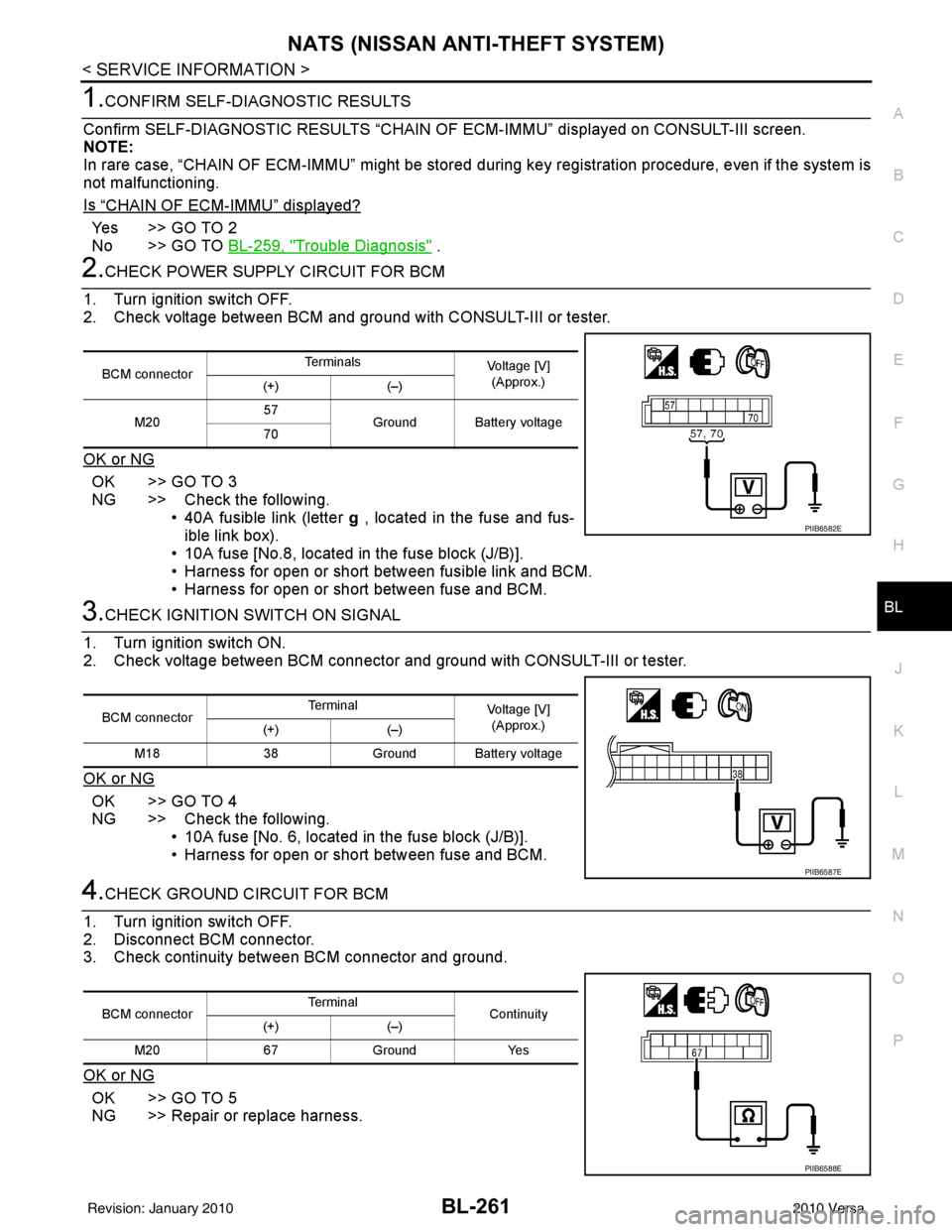
2.CHECK POWER SUPPLY CIRCUIT FOR BCM
1. Turn ignition switch OFF.
2. Check voltage between BCM and ground with CONSULT-III or tester.
OK or NG
OK >> GO TO 3
NG >> Check the following. • 40A fusible link (letter g , located in the fuse and fus-
ible link box).
• 10A fuse [No.8, located in the fuse block (J/B)].
• Harness for open or short between fusible link and BCM.
• Harness for open or short between fuse and BCM.
3.CHECK IGNITION SWITCH ON SIGNAL
1. Turn ignition switch ON.
2. Check voltage between BCM connector and ground with CONSULT-III or tester.
OK or NG
OK >> GO TO 4
NG >> Check the following. • 10A fuse [No. 6, located in the fuse block (J/B)].
• Harness for open or short between fuse and BCM.
4.CHECK GROUND CIRCUIT FOR BCM
1. Turn ignition switch OFF.
2. Disconnect BCM connector.
3. Check continuity between BCM connector and ground.
OK or NG
OK >> GO TO 5
NG >> Repair or replace harness.
BCM connector Te r m i n a l s
Voltage [V]
(Approx.)
(+) (–)
M20 57
Ground Battery voltage
70
PIIB6582E
BCM connector Terminal
Voltage [V]
(Approx.)
(+) (–)
M18 38Ground Battery voltage
PIIB6587E
BCM connector Terminal
Continuity
(+) (–)
M20 67 Ground Yes
PIIB6588E
Revision: January 20102010 Versa
Page 771 of 3745
BL-262
< SERVICE INFORMATION >
NATS (NISSAN ANTI-THEFT SYSTEM)
5.REPLACE BCM
1. Replace BCM. Refer to BCS-19, "
Removal and Installation of BCM".
2. Perform initialization with CONSULT-III.
For initialization, refer to “CONSULT-III Operation Manual NATS”.
Does the engine start?
Yes >> BCM is malfunctioning. • Replace BCM. Refer to BCS-19, "
Removal and Installation of BCM" .
• Perform initialization with CONSULT-III
• For initialization, refer to “CONSULT-III Operation Manual NATS”
No >> ECM is malfunctioning. • Replace ECM.
• Perform initialization or re-communicating function
• For initialization, refer to “CONSULT-III Operation Manual NATS”
• For re-communicating function, refer to BL-249, "
ECM Re-communicating Function"
Diagnosis Procedure 2INFOID:0000000005396712
Self-diagnostic results:
“CHAIN OF IMMU-KEY” displayed on CONSULT-III screen
1.CONFIRM SELF-DIAGNOSTIC RESULTS
Confirm SELF-DIAGNOSTIC RESULTS “CHAIN OF IMMU-KEY” displayed on CONSULT-III screen.
Is
“CHAIN OF IMMU-KEY” displayed?
Ye s > > G O T O 2
No >> GO TO BL-259, "
Trouble Diagnosis" .
2.CHECK NATS ANTENNA AMP. INSTALLATION
Check NATS antenna amp. installation. Refer to BL-266, "
How to Replace NATS Antenna Amp" .
OK or NG
OK >> GO TO 3
NG >> Reinstall NATS antenna amp. correctly.
3.CHECK NATS IGNITION KEY ID CHIP
Start engine with another registered NATS ignition key.
Does the engine start?
Yes >> Ignition key ID chip is malfunctioning. • Replace the ignition key
• Perform initialization with CONSULT-IIIFor initialization, refer to “CONSULT-III Operation Manual NATS”
No >> GO TO 4
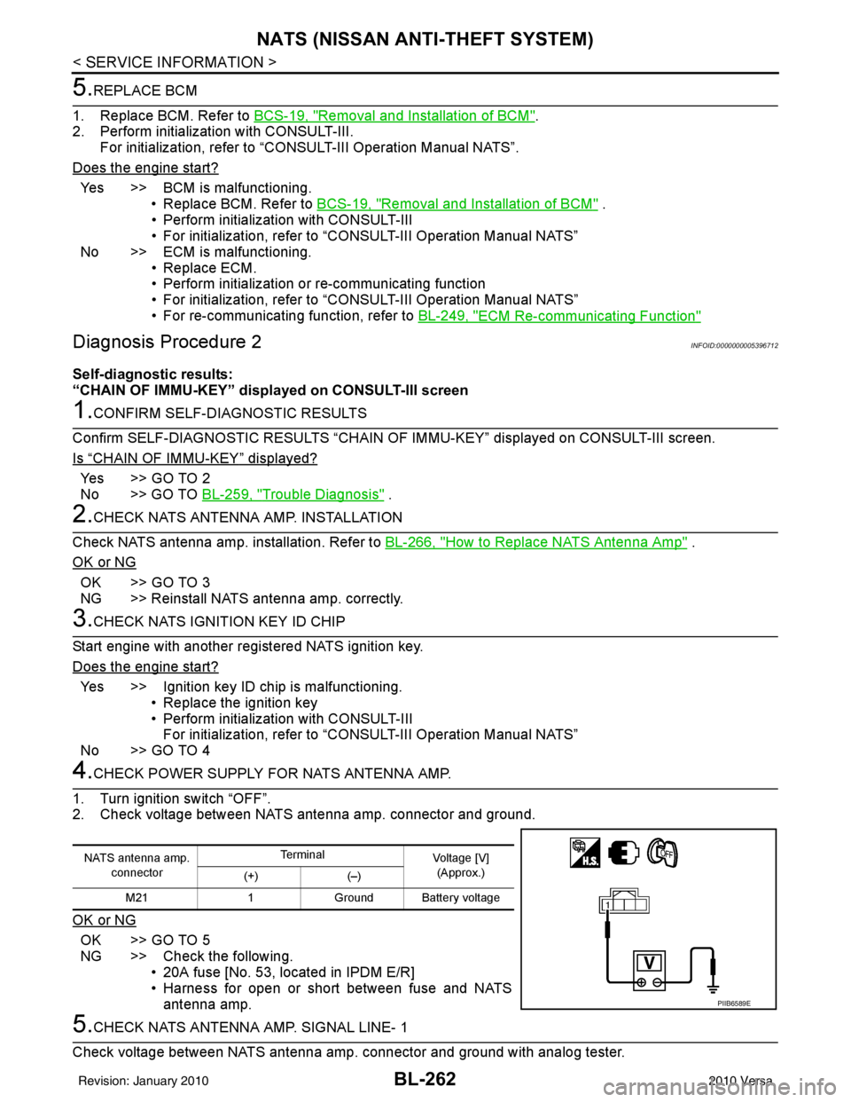
4.CHECK POWER SUPPLY FO R NATS ANTENNA AMP.
1. Turn ignition switch “OFF”.
2. Check voltage between NATS antenna amp. connector and ground.
OK or NG
OK >> GO TO 5
NG >> Check the following. • 20A fuse [No. 53, located in IPDM E/R]
• Harness for open or short between fuse and NATSantenna amp.
5.CHECK NATS ANTENNA AMP. SIGNAL LINE- 1
Check voltage between NATS antenna amp. connector and ground with analog tester.
NATS antenna amp. connector Te r m i n a l
Voltage [V]
(Approx.)
(+) (–)
M21 1Ground Battery voltage
PIIB6589E
Revision: January 20102010 Versa
Page 773 of 3745
BL-264
< SERVICE INFORMATION >
NATS (NISSAN ANTI-THEFT SYSTEM)
“ID DISCORD IMM-ECM”:
Registered ID of BCM is in discord with that of ECM.
Is
“ID DISCORD IMM-ECM” displayed?
Ye s > > G O T O 2
No >> GO TO BL-259, "
Trouble Diagnosis" .
2.PERFORM INITIALIZATION WITH CONSULT-III
Perform initialization with CONSULT-III. Re-register all NATS ignition key IDs.
For initialization, refer to “CONSULT-III Operation Manual NATS”.
NOTE:
If the initialization is not completed or ma lfunctions, CONSULT-III shows message on the screen.
Can the system be initialized?
Yes >> • Start engine. (END) • (System initialization had not been completed.)
No >> ECM is malfunctioning. • Replace ECM.
• Perform initialization with CONSULT-III
For initialization, refer to “CONSULT-III Operation Manual NATS”
Diagnosis Procedure 4INFOID:0000000005396714
“COMBINATION METER (SECURITY) DOES NOT LIGHT UP”
1.CHECK FUSE
Check 10A fuse [No.13, located in the fuse block (J/B)]
OK or NG
OK >> GO TO 2
NG >> Replace fuse.
2.CHECK COMBINATION METER (SECURITY)
1. Install 10A fuse.
2. Start engine and turn ignition switch OFF.
3. Check if the combination meter (security) lights up.
OK or NG
OK >> Inspection End.
NG >> GO TO 3
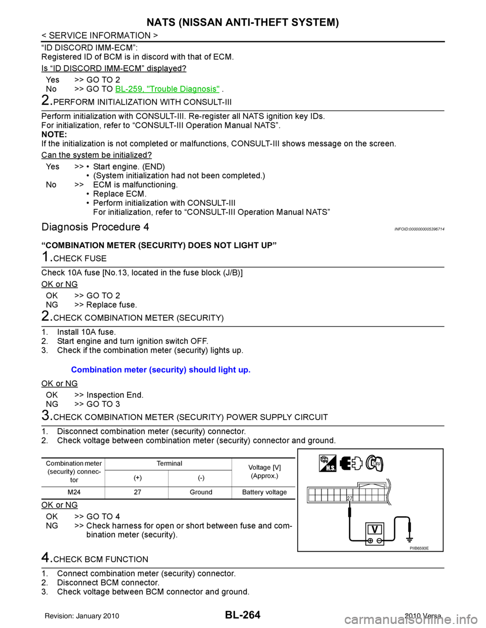
3.CHECK COMBINATION METER (SECURITY) POWER SUPPLY CIRCUIT
1. Disconnect combination meter (security) connector.
2. Check voltage between combination meter (security) connector and ground.
OK or NG
OK >> GO TO 4
NG >> Check harness for open or short between fuse and com- bination meter (security).
4.CHECK BCM FUNCTION
1. Connect combination meter (security) connector.
2. Disconnect BCM connector.
3. Check voltage between BCM connector and ground. Combination meter (security) should light up.
Combination meter
(security) connec-
tor Te r m i n a l
Voltage [V]
(Approx.)
(+) (-)
M24 27Ground Battery voltage
PIIB6593E
Revision: January 20102010 Versa