2010 NISSAN LATIO fuse
[x] Cancel search: fusePage 505 of 3745
BCS-16
< SERVICE INFORMATION >
BCM (BODY CONTROL MODULE)
1: With Intelligent Key
2: Without Intelligent Key
3: Hatchback without Intelligent Key
4: Sedan without Intelligent Key
5: Hatchback
6: Sedan
7: With power door locks
8: With power windows
BCM Power Supply and Ground Circuit InspectionINFOID:0000000005395108
1.CHECK FUSES AND FUSIBLE LINK
• Check 40A fusible link (letter g , located in the fuse and fusible link box).
• Check 10A fuses [No. 6, 8 and 20, lo cated in the fuse block (J/B)].
OK or NG
OK >> GO TO 2.
NG >> If fuse is blown, be sure to eliminate cause of malfunction before installing new fuse. Refer to PG-
4, "Schematic" .
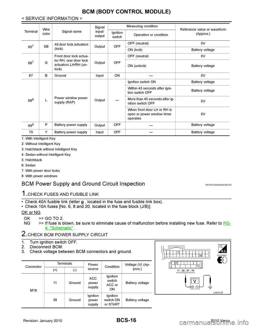
2.CHECK BCM POWER SUPPLY CIRCUIT
1. Turn ignition switch OFF.
2. Disconnect BCM.
3. Check voltage between BCM connectors and ground.
657SB All door lock actuators
(lock) Output OFFOFF (neutral)
0V
ON (lock) Battery voltage
66
7G Front door lock actua-
tor RH, rear door lock
actuators LH/RH (un-
lock) Output OFFOFF (neutral)
0V
ON (unlock) Battery voltage
67 B Ground Input ON—0V
68
8L Power window power
supply (RAP)
Output —Ignition switch ON
Battery voltage
Within 45 seconds after igni-
tion switch OFF Battery voltage
More than 45 seconds after ig-
nition switch OFF 0V
When front door LH or RH is
open or power window timer
operates 0V
69
8P Battery power supply OutputOFF
— Battery voltage
70 Y Battery power supply Input OFF —Battery voltage
Te r m i n a l
Wire
color Signal name Signal
input/
output Measuring condition
Reference value or waveform
(Approx.)
Ignition
switch Operation or condition
Connector Te r m i n a l s
Power
source Condition Voltage (V) (Ap-
prox.)
(+) (-)
M18 11 Ground
ACC
power
supply Ignition
switch
ACC or
ON Battery voltage
38 Ground Ignition
power
supply Ignition
switch ON or START Battery voltage
LIIA2415E
Revision: January 20102010 Versa
Page 532 of 3745

POWER DOOR LOCK SYSTEMBL-23
< SERVICE INFORMATION >
C
DE
F
G H
J
K L
M A
B
BL
N
O P
System DescriptionINFOID:0000000005396554
Power is supplied at all times
• through 40A fusible link (letter g , located in the fuse and fusible link box)
• to BCM terminal 70
• through 10A fuse [No. 8, located in the fuse block (J/B)]
• to BCM terminal 57
• through 10A fuse [No. 14, located in the fuse block (J/B)]
• to key switch terminal 2 (without Intelligent Key system)
• through 10A fuse [No. 31, located in the fuse block (J/B)]
• to key switch and ignition knob switch terminals 2 and 4 (with Intelligent Key system).
When key switch is ON (key is inserted in ignition key cylinder), power is supplied
• through key switch terminal 1 (without Intelligent Key system) or key switch and ignition knob terminal 1 (with Intelligent Key system)
• to BCM terminal 37.
Ground is supplied
• to BCM terminal 67
• through body grounds M57 and M61.
LOCK OPERATION
When the door is locked with main power window and door lock/unlock switch, ground is supplied
• to BCM terminal 45
• through main power window and door lock and unlock switch terminals 17 and 18
• through body grounds M57 and M61.
When the door is locked with power window and door lock/unlock switch RH, ground is supplied
• to BCM terminal 45
• through power window and door lock and unlock switch RH terminals 1 and 3
• through body grounds M57 and M61.
When the door is locked with front door ke y cylinder switch LH, ground is supplied
• to BCM terminal 8
• through front door key cylinder switch LH terminals 1 and 2
• through body grounds M57 and M61.
UNLOCK OPERATION
When the door is unlocked with main power window and door lock/unlock switch, ground is supplied
• to BCM terminal 46
• through main power window and door lock/unlock switch terminals 6 and 17
• through body grounds M57 and M61.
When the door is unlocked with power window and door lock/unlock switch RH, ground is supplied
• to BCM terminal 46
• through power window and door lock and unlock switch RH terminals 2 and 3
• through body grounds M57 and M61.
When the door is unlocked with front door ke y cylinder switch LH, ground is supplied
• to BCM terminal 7
• through front door key cylinder switch LH terminals 2 and 3
• through body grounds M57 and M61.
When the front door switch LH is ON (door is OPEN), ground is supplied
• to BCM terminal 47
• through front door switch LH terminal 2
• through front door switch LH case ground.
When the front door switch RH is ON (door is OPEN), ground is supplied
• to BCM terminal 12
• through front door switch RH terminal 2
• through front door switch RH case ground.
10. Key switch and key lock solenoid M27
(without Intelligent key) 11. Main power window and door lock/un-
lock switch D7, D8
Power window and door lock/unlock
switch RH D105 12. Fuse block (with Intelligent Key)
(view with instrument panel LH re-
moved)
13. Passenger select unlock relay M2 (with Intelligent Key) 14. Back door lock assembly (back door
switch) D405 (hatchback view with back
door open) 15. Combination meter M24
Revision: January 20102010 Versa
Page 552 of 3745
POWER DOOR LOCK SYSTEMBL-43
< SERVICE INFORMATION >
C
DE
F
G H
J
K L
M A
B
BL
N
O P
Trouble Diagnosis Symptom ChartINFOID:0000000005396563
BCM Power Supply and Gr ound Circuit InspectionINFOID:0000000005612414
1.CHECK FUSES AND FUSIBLE LINK
• Check 40A fusible link (letter g , located in the fuse and fusible link box).
• Check 10A fuses [No. 6, 8 and 20, lo cated in the fuse block (J/B)].
OK or NG
OK >> GO TO 2.
NG >> If fuse is blown, be sure to eliminate cause of malfunction before installing new fuse. Refer to PG-
4, "Schematic" .
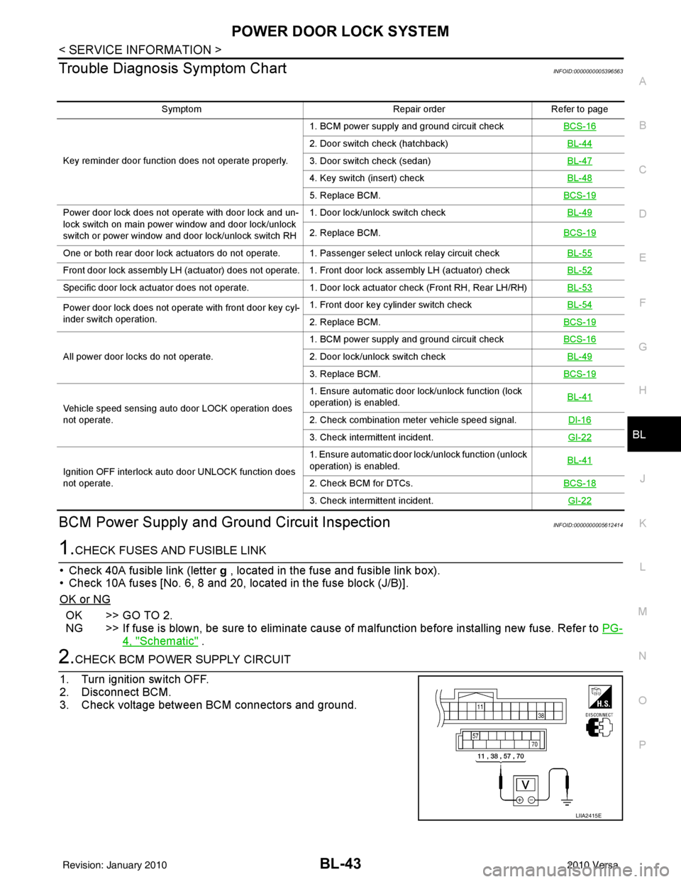
2.CHECK BCM POWER SUPPLY CIRCUIT
1. Turn ignition switch OFF.
2. Disconnect BCM.
3. Check voltage between BCM connectors and ground.
Symptom Repair orderRefer to page
Key reminder door function does not operate properly. 1. BCM power supply and ground circuit check
BCS-16
2. Door switch check (hatchback) BL-44
3. Door switch check (sedan)BL-47
4. Key switch (insert) checkBL-48
5. Replace BCM.BCS-19
Power door lock does not operate with door lock and un-
lock switch on main power window and door lock/unlock
switch or power window and door lock/unlock switch RH1. Door lock/unlock switch check
BL-49
2. Replace BCM.BCS-19
One or both rear door lock actuators do not operate. 1. Passenger select unlock relay circuit check BL-55
Front door lock assembly LH (actuator) does not operate. 1. Front door lock assembly LH (actuator) checkBL-52
Specific door lock actuator does not operate.1. Door lock actuator check (Front RH, Rear LH/RH) BL-53
Power door lock does not operate with front door key cyl-
inder switch operation.1. Front door key cylinder switch check
BL-54
2. Replace BCM.BCS-19
All power door locks do not operate.1. BCM power supply and ground circuit check
BCS-162. Door lock/unlock switch check BL-49
3. Replace BCM.BCS-19
Vehicle speed sensing auto door LOCK operation does
not operate.1. Ensure automatic door lock/unlock function (lock
operation) is enabled.
BL-41
2. Check combination meter vehicle speed signal.
DI-16
3. Check intermittent incident.GI-22
Ignition OFF interlock auto door UNLOCK function does
not operate.1. Ensure automatic door lock/unlock function (unlock
operation) is enabled.
BL-41
2. Check BCM for DTCs.
BCS-18
3. Check intermittent incident. GI-22
LIIA2415E
Revision: January 20102010 Versa
Page 558 of 3745
POWER DOOR LOCK SYSTEMBL-49
< SERVICE INFORMATION >
C
DE
F
G H
J
K L
M A
B
BL
N
O P
OK or NG
OK >> Check the following. • 10A fuse (No. 31, located in fuse and fusible linkblock)
• Harness for open or short between key switch and ignition knob switch and fuse
• Harness for open or short between BCM and key switch and ignition knob switch
NG >> Replace key switch and ignition knob switch.
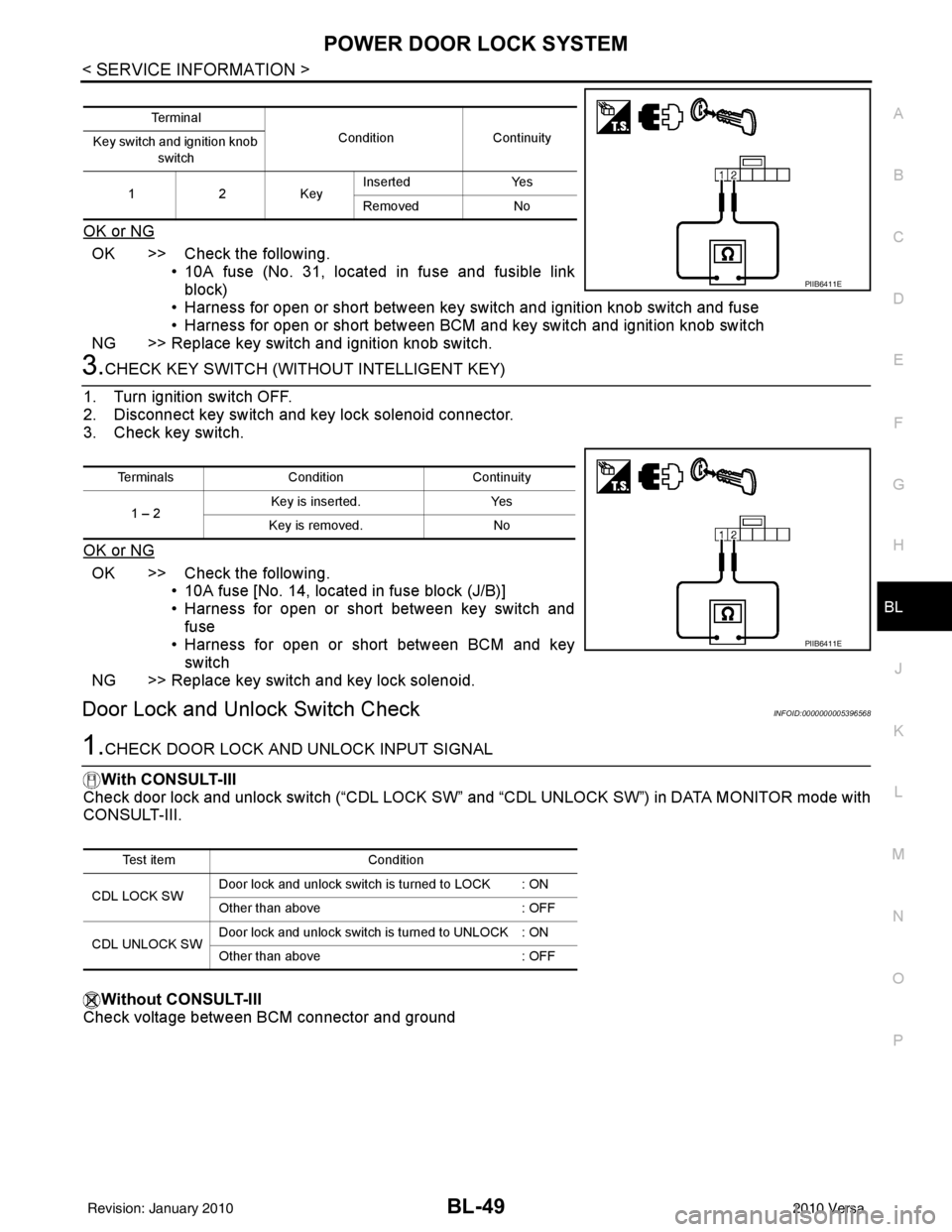
3.CHECK KEY SWITCH (WITHO UT INTELLIGENT KEY)
1. Turn ignition switch OFF.
2. Disconnect key switch and key lock solenoid connector.
3. Check key switch.
OK or NG
OK >> Check the following. • 10A fuse [No. 14, located in fuse block (J/B)]
• Harness for open or short between key switch and
fuse
• Harness for open or short between BCM and key
switch
NG >> Replace key switch and key lock solenoid.
Door Lock and Unlock Switch CheckINFOID:0000000005396568
1.CHECK DOOR LOCK AND UNLOCK INPUT SIGNAL
With CONSULT-III
Check door lock and unlock switch (“CDL LOCK SW” and “CDL UNLOCK SW”) in DATA MONITOR mode with
CONSULT-III.
Without CONSULT-III
Check voltage between BCM connector and ground
Te r m i n a l
ConditionContinuity
Key switch and ignition knob
switch
12K ey Inserted
Yes
Removed No
PIIB6411E
Terminals Condition Continuity
1 – 2 Key is inserted.
Yes
Key is removed. No
PIIB6411E
Test item Condition
CDL LOCK SW Door lock and unlock switch is turned to LOCK : ON
Other than above
: OFF
CDL UNLOCK SW Door lock and unlock switch is turned to UNLOCK : ON
Other than above
: OFF
Revision: January 20102010 Versa
Page 567 of 3745
BL-58
< SERVICE INFORMATION >
REMOTE KEYLESS ENTRY SYSTEM
REMOTE KEYLESS ENTRY SYSTEM
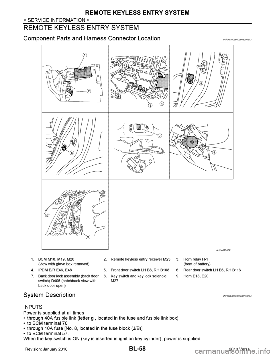
Component Parts and Harness Connector LocationINFOID:0000000005396573
System DescriptionINFOID:0000000005396574
INPUTS
Power is supplied at all times
• through 40A fusible link (letter g , located in the fuse and fusible link box)
• to BCM terminal 70
• through 10A fuse [No. 8, located in the fuse block (J/B)]
• to BCM terminal 57.
When the key switch is ON (key is inserted in ignition key cylinder), power is supplied
ALKIA1754ZZ
1. BCM M18, M19, M20
(view with glove box removed) 2. Remote keyless entry receiver M23 3. Horn relay H-1
(front of battery)
4. IPDM E/R E46, E48 5. Front door switch LH B8, RH B108 6. Rear door switch LH B6, RH B116
7. Back door lock assembly (back door switch) D405 (hatchback view with
back door open) 8. Key switch and key lock solenoid
M27 9. Horn E18, E20
Revision: January 20102010 Versa
Page 568 of 3745
![NISSAN LATIO 2010 Service Repair Manual REMOTE KEYLESS ENTRY SYSTEMBL-59
< SERVICE INFORMATION >
C
DE
F
G H
J
K L
M A
B
BL
N
O P
• through 10A fuse [No. 14, located in the fuse block (J/B)]
• through key switch terminals 2 and 1
• to NISSAN LATIO 2010 Service Repair Manual REMOTE KEYLESS ENTRY SYSTEMBL-59
< SERVICE INFORMATION >
C
DE
F
G H
J
K L
M A
B
BL
N
O P
• through 10A fuse [No. 14, located in the fuse block (J/B)]
• through key switch terminals 2 and 1
• to](/manual-img/5/57358/w960_57358-567.png)
REMOTE KEYLESS ENTRY SYSTEMBL-59
< SERVICE INFORMATION >
C
DE
F
G H
J
K L
M A
B
BL
N
O P
• through 10A fuse [No. 14, located in the fuse block (J/B)]
• through key switch terminals 2 and 1
• to BCM terminal 37.
When the ignition switch is ACC or ON, power is supplied
• through 10A fuse [No. 20, located in the fuse block (J/B)]
• to BCM terminal 11.
Ground is supplied
• to BCM terminal 67
• through body grounds M57 and M61.
When the front door switch LH is ON (door is OPEN), ground is supplied
• to BCM terminal 47
• through front door switch LH terminal 2
• through front door switch LH case ground.
When the front door switch RH is ON (door is OPEN), ground is supplied
• to BCM terminal 12
• through front door switch RH terminal 2
• through front door switch RH case ground.
When the rear door switch LH is ON (door is OPEN), ground is supplied
• to BCM terminal 48
• through rear door switch LH terminal 1
• through rear door switch LH case ground.
When the rear door switch RH is ON (door is OPEN), ground is supplied
• to BCM meter terminal 13
• through rear door switch RH terminal 1
• through rear door switch RH case ground.
When the back door lock assembly (back door switch) (hat chback) is ON (back door is OPEN), ground is sup-
plied
• to BCM terminal 43
• through back door lock assembly (back door switch) terminals 3 and 4
• through body grounds B117, B132 and D402.
Keyfob signal is inputted to BCM from remote keyless entry receiver.
The remote keyless entry system controls operation of the
• power door lock
• hazard reminder
• auto door lock
• panic alarm
• room lamp
OPERATED PROCEDURE
Power Door Lock Operation
BCM receives a LOCK signal from keyfob. BCM locks all doors with input of LOCK signal from keyfob.
BCM receives a UNLOCK signal from keyfob. BCM unlocks all doors with input of UNLOCK signal from key-
fob.
Hazard and Horn Reminder
When the doors are locked or unlocked by keyfob, power is supplied to sound horn and flash hazard warning
lamps as follows
• LOCK operation: 3 or 4 mode (lamps flash twice)
• UNLOCK operation: 2 or 4 mode (lamps flash once)
• Horn sounds once with LOCK function when this feature is set ON.
The hazard reminder has modes 1, 2, 3 or 4. The hor n reminder can be turned ON/OFF with any LOCK mode.
Operating function of hazard reminder
Hazard and horn reminders do not operate if any door switch is ON (any door is OPEN).
How to change hazard and horn reminder modes
Mode 1Mode 2Mode 3 Mode 4
Keyfob operation Lock Unlock Lock Unlock Lock Unlock Lock Unlock
Hazard warning lamp
flash — — — Twice Once — Once Twice
Horn sound (ON/OFF) ON: once — O N: once — ON: once — ON: once —
Revision: January 20102010 Versa
Page 583 of 3745
BL-74
< SERVICE INFORMATION >
REMOTE KEYLESS ENTRY SYSTEM
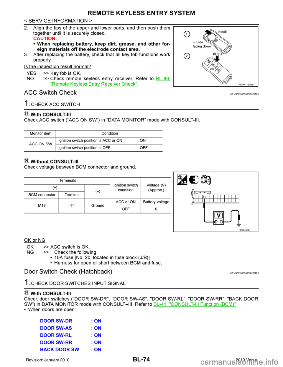
2. Align the tips of the upper and lower parts, and then push themtogether until it is securely closed.
CAUTION:
• When replacing battery, keep dirt, grease, and other for-eign materials off the electrode contact area.
3. After replacing the battery, check that all key fob functions work
properly.
Is the inspection result normal?
YES >> Key fob is OK.
NO >> Check remote keyless entry receiver. Refer to BL-80,
"Remote Keyless Entry Receiver Check".
ACC Switch CheckINFOID:0000000005396585
1.CHECK ACC SWITCH
With CONSULT-III
Check ACC switch (“ACC ON SW”) in “DATA MONITOR” mode with CONSULT-III.
Without CONSULT-III
Check voltage between BCM connector and ground.
OK or NG
OK >> ACC switch is OK.
NG >> Check the following. • 10A fuse [No. 20, located in fuse block (J/B)]
• Harness for open or short between BCM and fuse.
Door Switch Check (Hatchback)INFOID:0000000005396586
1.CHECK DOOR SWITCHES INPUT SIGNAL
With CONSULT-III
Check door switches ("DOOR SW-DR", "DOOR SW-AS", "DOOR SW-RL", "DOOR SW-RR", "BACK DOOR
SW") in DATA MONITOR mode with CONSULT–III. Refer to BL-41, "
CONSULT-III Function (BCM)" .
• When doors are open:
ALKIA1721GB
Monitor item Condition
ACC ON SW Ignition switch position is ACC or ON : ON
Ignition switch position is OFF
: OFF
Te r m i n a l s
Ignition switch
condition Voltage (V)
(Approx.)
(+)
(–)
BCM connector Terminal
M18 11 Ground ACC or ON Battery voltage
OFF 0
PIIB6453E
DOOR SW-DR : ON
DOOR SW-AS : ON
DOOR SW-RL : ON
DOOR SW-RR : ON
BACK DOOR SW : ON
Revision: January 20102010 Versa
Page 587 of 3745
BL-78
< SERVICE INFORMATION >
REMOTE KEYLESS ENTRY SYSTEM
Key Switch (I nsert) Check
INFOID:0000000005396588
1.CHECK KEY SWITCH INPUT SIGNAL
With CONSULT-III
Check key switch "KEY ON SW" in DATA MONITOR mode with CONSULT–III. Refer to BL-41, "
CONSULT-III
Function (BCM)" .
• When key is inserted into ignition key cylinder:
• When key is removed from ignition key cylinder:
Without CONSULT-III
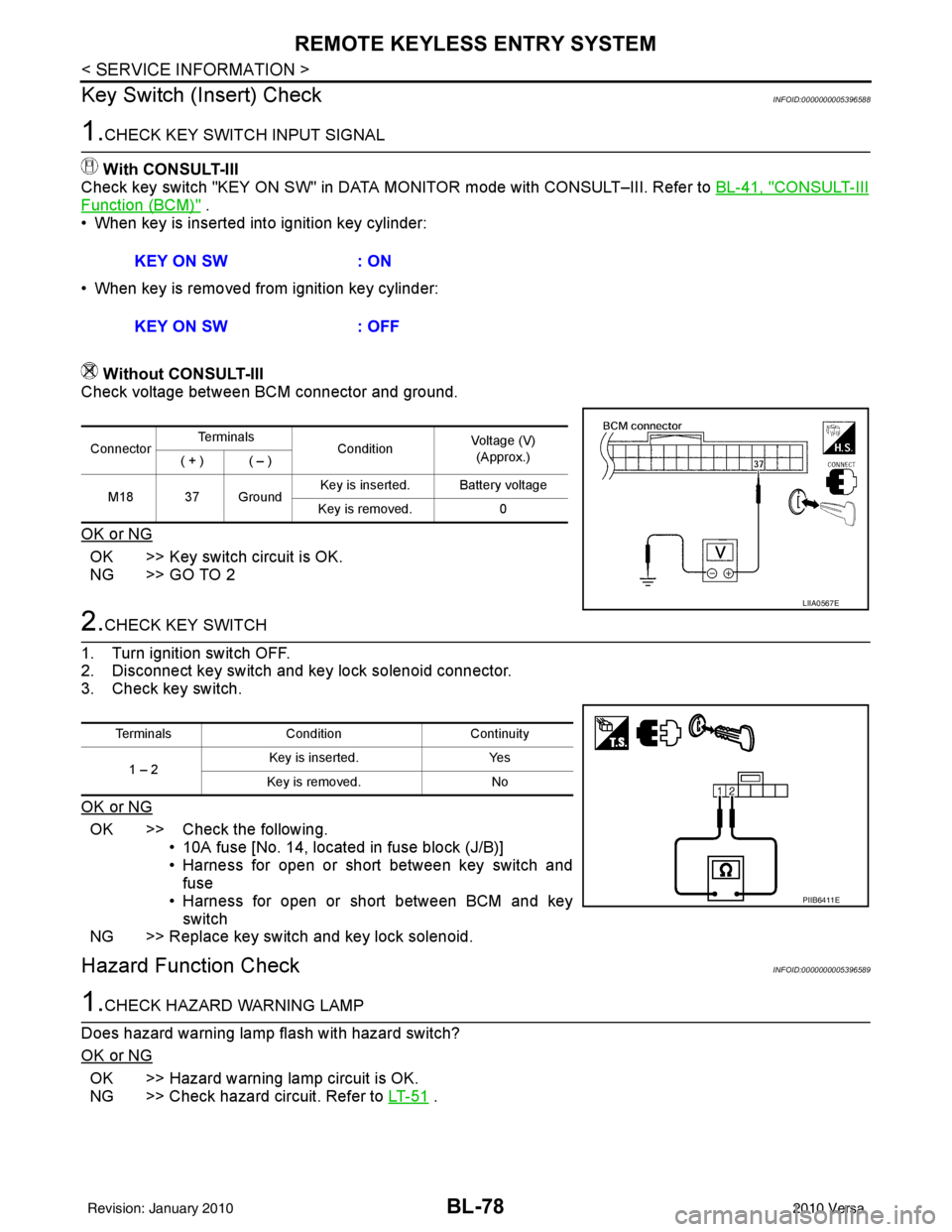
Check voltage between BCM connector and ground.
OK or NG
OK >> Key switch circuit is OK.
NG >> GO TO 2
2.CHECK KEY SWITCH
1. Turn ignition switch OFF.
2. Disconnect key switch and key lock solenoid connector.
3. Check key switch.
OK or NG
OK >> Check the following. • 10A fuse [No. 14, located in fuse block (J/B)]
• Harness for open or short between key switch andfuse
• Harness for open or short between BCM and key switch
NG >> Replace key switch and key lock solenoid.
Hazard Function CheckINFOID:0000000005396589
1.CHECK HAZARD WARNING LAMP
Does hazard warning lamp flash with hazard switch?
OK or NG
OK >> Hazard warning lamp circuit is OK.
NG >> Check hazard circuit. Refer to LT- 5 1
.
KEY ON SW
: ON
KEY ON SW : OFF
ConnectorTe r m i n a l s
ConditionVoltage (V)
(Approx.)
( + ) ( – )
M18 37 Ground Key is inserted. Battery voltage
Key is removed. 0
LIIA0567E
TerminalsCondition Continuity
1 – 2 Key is inserted.
Yes
Key is removed. No
PIIB6411E
Revision: January 20102010 Versa