2010 NISSAN LATIO Lan system
[x] Cancel search: Lan systemPage 2991 of 3745
![NISSAN LATIO 2010 Service Repair Manual LAN-182
< SERVICE INFORMATION >[CAN SYSTEM (TYPE 14)]
ABS BRANCH LINE CIRCUIT
ABS BRANCH LINE CIRCUIT
Diagnosis ProcedureINFOID:0000000005531966
1.CHECK CONNECTOR
1. Turn the ignition switch OFF.
2. D NISSAN LATIO 2010 Service Repair Manual LAN-182
< SERVICE INFORMATION >[CAN SYSTEM (TYPE 14)]
ABS BRANCH LINE CIRCUIT
ABS BRANCH LINE CIRCUIT
Diagnosis ProcedureINFOID:0000000005531966
1.CHECK CONNECTOR
1. Turn the ignition switch OFF.
2. D](/manual-img/5/57358/w960_57358-2990.png)
LAN-182
< SERVICE INFORMATION >[CAN SYSTEM (TYPE 14)]
ABS BRANCH LINE CIRCUIT
ABS BRANCH LINE CIRCUIT
Diagnosis ProcedureINFOID:0000000005531966
1.CHECK CONNECTOR
1. Turn the ignition switch OFF.
2. Disconnect the battery cable from the negative terminal.
3. Check the terminals and connectors of the ABS actuator and electric unit (control unit) for damage, bend and loose connection (unit side and connector side).
Is the inspection result normal?
YES >> GO TO 2.
NO >> Repair the terminal and connector.
2.CHECK HARNESS FOR OPEN CIRCUIT
1. Disconnect the connector of ABS actuat or and electric unit (control unit).
2. Check the resistance between the ABS actuator and electric unit (control unit) harness connector termi-
nals.
Is the measurement value within the specification?
YES >> GO TO 3.
NO >> Repair the ABS actuator and electric unit (control unit) branch line.
3.CHECK POWER SUPPLY AND GROUND CIRCUIT
Check the power supply and the ground circuit of the ABS ac tuator and electric unit (control unit). Refer to the
following.
• Models with ABS: BRC-29, "
ABS Control Unit Power and Ground Systems Inspection"
• Models with VDC: BRC-75, "ABS/TCS/VDC Control Unit Power and Ground Systems Inspection"
Is the inspection result normal?
YES (Present error)>>Replace the ABS actuator and electric unit (control unit). Refer to the following.
• Models with ABS: BRC-37, "
Removal and Installation"
• Models with VDC: BRC-89, "Removal and Installation"
YES (Past error)>>Error was detected in the ABS actuator and electric unit (control unit) branch line.
NO >> Repair the power supply and the ground circuit.
ABS actuator and electric unit (control unit) harness connector
Resistance (Ω)
Connector No. Terminal No.
E33 2615Approx. 54 – 66
Revision: January 20102010 Versa
Page 2992 of 3745
![NISSAN LATIO 2010 Service Repair Manual TCM BRANCH LINE CIRCUITLAN-183
< SERVICE INFORMATION > [CAN SYSTEM (TYPE 14)]
C
D
E
F
G H
I
J
L
M A
B
LAN
N
O P
TCM BRANCH LINE CIRCUIT
Diagnosis ProcedureINFOID:0000000005531967
1.CHECK CONNECTOR
1. NISSAN LATIO 2010 Service Repair Manual TCM BRANCH LINE CIRCUITLAN-183
< SERVICE INFORMATION > [CAN SYSTEM (TYPE 14)]
C
D
E
F
G H
I
J
L
M A
B
LAN
N
O P
TCM BRANCH LINE CIRCUIT
Diagnosis ProcedureINFOID:0000000005531967
1.CHECK CONNECTOR
1.](/manual-img/5/57358/w960_57358-2991.png)
TCM BRANCH LINE CIRCUITLAN-183
< SERVICE INFORMATION > [CAN SYSTEM (TYPE 14)]
C
D
E
F
G H
I
J
L
M A
B
LAN
N
O P
TCM BRANCH LINE CIRCUIT
Diagnosis ProcedureINFOID:0000000005531967
1.CHECK CONNECTOR
1. Turn the ignition switch OFF.
2. Disconnect the battery cabl e from the negative terminal.
3. Check the terminals and connector of the TCM for damage, bend and loose connection (unit side and connector side).
Is the inspection result normal?
YES >> GO TO 2.
NO >> Repair the terminal and connector.
2.CHECK HARNESS FOR OPEN CIRCUIT
1. Disconnect the connector of TCM.
2. Check the resistance between the TCM harness connector terminals.
Is the measurement value within the specification?
YES >> GO TO 3.
NO >> Repair the TCM branch line.
3.CHECK POWER SUPPLY AND GROUND CIRCUIT
Check the power supply and the ground circuit of the TCM. Refer to the following.
• A/T models: AT-169, "
Diagnosis Procedure"
• CVT models: CVT-115, "Diagnosis Procedure"
Is the inspection result normal?
YES (Present error)>>Replace the TCM. Refer to the following.
• A/T models: AT-212, "
Removal and Installation"
• CVT models: CVT-159, "Removal and Installation"
YES (Past error)>>Error was detected in the TCM branch line.
NO >> Repair the power supply and the ground circuit.
TCM harness connector
Resistance (Ω)
Connector No. Terminal No.
E31 5 6 Approx. 54 – 66
Revision: January 20102010 Versa
Page 2993 of 3745
![NISSAN LATIO 2010 Service Repair Manual LAN-184
< SERVICE INFORMATION >[CAN SYSTEM (TYPE 14)]
IPDM-E BRANCH LINE CIRCUIT
IPDM-E BRANCH LINE CIRCUIT
Diagnosis ProcedureINFOID:0000000005531968
1.CHECK CONNECTOR
1. Turn the ignition switch OFF NISSAN LATIO 2010 Service Repair Manual LAN-184
< SERVICE INFORMATION >[CAN SYSTEM (TYPE 14)]
IPDM-E BRANCH LINE CIRCUIT
IPDM-E BRANCH LINE CIRCUIT
Diagnosis ProcedureINFOID:0000000005531968
1.CHECK CONNECTOR
1. Turn the ignition switch OFF](/manual-img/5/57358/w960_57358-2992.png)
LAN-184
< SERVICE INFORMATION >[CAN SYSTEM (TYPE 14)]
IPDM-E BRANCH LINE CIRCUIT
IPDM-E BRANCH LINE CIRCUIT
Diagnosis ProcedureINFOID:0000000005531968
1.CHECK CONNECTOR
1. Turn the ignition switch OFF.
2. Disconnect the battery cable from the negative terminal.
3. Check the following terminals and connectors fo r damage, bend and loose connection (unit side and con-
nector side).
- IPDM E/R
- Harness connector E7 (M/T models without ABS)
- Harness connector M69 (M /T models without ABS)
Is the inspection result normal?
YES >> GO TO 2.
NO >> Repair the terminal and connector.
2.CHECK HARNESS FOR OPEN CIRCUIT
1. Disconnect the connector of IPDM E/R.
2. Check the resistance between the IPDM E/R harness connector terminals.
Is the measurement value within the specification?
YES >> GO TO 3.
NO >> Repair the IPDM E/R branch line.
3.CHECK POWER SUPPLY AND GROUND CIRCUIT
Check the power supply and the ground circ uit of the IPDM E/R. Refer to PG-27, "
IPDM E/R Power/Ground
Circuit Inspection".
Is the inspection result normal?
YES (Present error)>>Replace the IPDM E/R. Refer to PG-28, "Removal and Installation of IPDM E/R".
YES (Past error)>>Error was detected in the IPDM E/R branch line.
NO >> Repair the power supply and the ground circuit.
IPDM E/R harness connector Resistance (Ω)
Connector No. Terminal No.
E46 4140Approx. 108 – 132
Revision: January 20102010 Versa
Page 2994 of 3745
![NISSAN LATIO 2010 Service Repair Manual CAN COMMUNICATION CIRCUITLAN-185
< SERVICE INFORMATION > [CAN SYSTEM (TYPE 14)]
C
D
E
F
G H
I
J
L
M A
B
LAN
N
O P
CAN COMMUNICATION CIRCUIT
Diagnosis ProcedureINFOID:0000000005531969
1.CONNECTOR INSPE NISSAN LATIO 2010 Service Repair Manual CAN COMMUNICATION CIRCUITLAN-185
< SERVICE INFORMATION > [CAN SYSTEM (TYPE 14)]
C
D
E
F
G H
I
J
L
M A
B
LAN
N
O P
CAN COMMUNICATION CIRCUIT
Diagnosis ProcedureINFOID:0000000005531969
1.CONNECTOR INSPE](/manual-img/5/57358/w960_57358-2993.png)
CAN COMMUNICATION CIRCUITLAN-185
< SERVICE INFORMATION > [CAN SYSTEM (TYPE 14)]
C
D
E
F
G H
I
J
L
M A
B
LAN
N
O P
CAN COMMUNICATION CIRCUIT
Diagnosis ProcedureINFOID:0000000005531969
1.CONNECTOR INSPECTION
1. Turn the ignition switch OFF.
2. Disconnect the battery cabl e from the negative terminal.
3. Disconnect all the unit connectors on CAN communication system.
4. Check terminals and connectors for damage, bend and loose connection.
Is the inspection result normal?
YES >> GO TO 2.
NO >> Repair the terminal and connector.
2.CHECK HARNESS CONTINUI TY (SHORT CIRCUIT)
Check the continuity between the data link connector terminals.
Is the inspection result normal?
YES >> GO TO 3.
NO >> Check the harness and repair the root cause.
3.CHECK HARNESS CONTINUI TY (SHORT CIRCUIT)
Check the continuity between the data link connector and the ground.
Is the inspection result normal?
YES >> GO TO 4.
NO >> Check the harness and repair the root cause.
4.CHECK ECM AND IPDM E/R TERMINATION CIRCUIT
1. Remove the ECM and the IPDM E/R.
2. Check the resistance between the ECM terminals.
3. Check the resistance between the IPDM E/R terminals.
Is the measurement value within the specification?
YES >> GO TO 5.
NO >> Replace the ECM and/or the IPDM E/R.
5.CHECK SYMPTOM
Connect all the connectors. Check if the symptoms descr ibed in the “Symptom (Results from interview with
customer)” are reproduced.
Data link connector Continuity
Connector No. Terminal No.
M22 6 14 Not existed
Data link connector
GroundContinuity
Connector No. Terminal No.
M22 6
Not existed
14 Not existed
ECM
Resistance (Ω)
Te r m i n a l N o .
84 83 Approx. 108 – 132
IPDM E/R Resistance (Ω)
Te r m i n a l N o .
41 40Approx. 108 – 132
LKIA0037E
Revision: January 20102010 Versa
Page 2995 of 3745
![NISSAN LATIO 2010 Service Repair Manual LAN-186
< SERVICE INFORMATION >[CAN SYSTEM (TYPE 14)]
CAN COMMUNICATION CIRCUIT
Inspection result
Reproduced>>GO TO 6.
Non-reproduced>>Start the diagnosis again. Follow
the trouble diagnosis procedur NISSAN LATIO 2010 Service Repair Manual LAN-186
< SERVICE INFORMATION >[CAN SYSTEM (TYPE 14)]
CAN COMMUNICATION CIRCUIT
Inspection result
Reproduced>>GO TO 6.
Non-reproduced>>Start the diagnosis again. Follow
the trouble diagnosis procedur](/manual-img/5/57358/w960_57358-2994.png)
LAN-186
< SERVICE INFORMATION >[CAN SYSTEM (TYPE 14)]
CAN COMMUNICATION CIRCUIT
Inspection result
Reproduced>>GO TO 6.
Non-reproduced>>Start the diagnosis again. Follow
the trouble diagnosis procedure when past error is
detected.
6.CHECK UNIT REPRODUCTION
Perform the reproduction test as per the following procedure for each unit.
1. Turn the ignition switch OFF.
2. Disconnect the battery cable from the negative terminal.
3. Disconnect one of the unit connectors of CAN communication system. NOTE:
ECM and IPDM E/R have a termination circuit. Check other units first.
4. Connect the battery cable to the negative terminal. Check if the symptoms described in the “Symptom
(Results from interview with customer)” are reproduced.
NOTE:
Although unit-related error symptoms occur, do not confuse them with other symptoms.
Inspection result
Reproduced>>Connect the connector. Check other units as per the above procedure.
Non-reproduced>>Replace the unit whose connector was disconnected.
Revision: January 20102010 Versa
Page 3002 of 3745

HEADLAMP (FOR USA)LT-7
< SERVICE INFORMATION >
C
DE
F
G H
I
J
L
M A
B
LT
N
O P
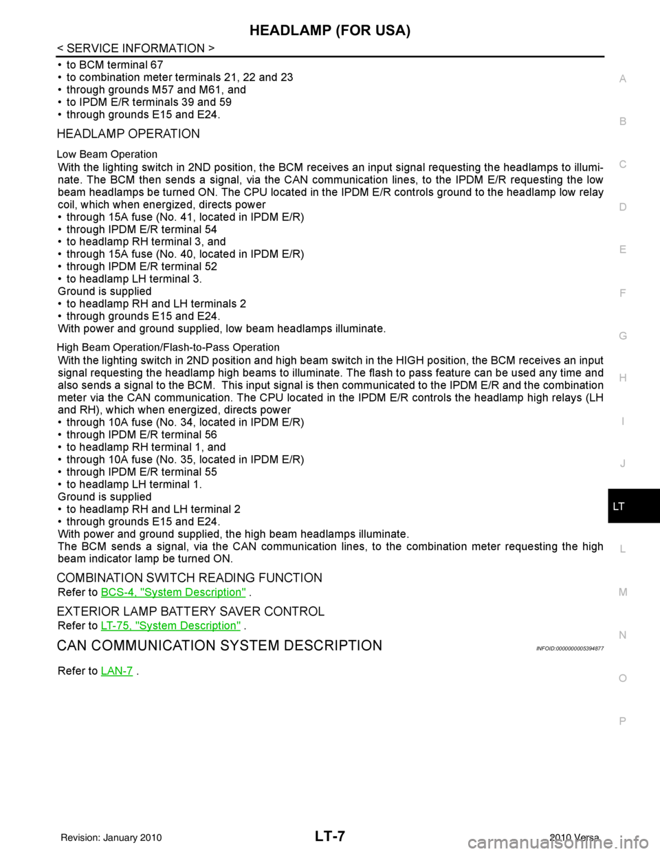
• to BCM terminal 67
• to combination meter terminals 21, 22 and 23
• through grounds M57 and M61, and
• to IPDM E/R terminals 39 and 59
• through grounds E15 and E24.
HEADLAMP OPERATION
Low Beam Operation
With the lighting switch in 2ND position, the BCM re ceives an input signal requesting the headlamps to illumi-
nate. The BCM then sends a signal, via the CAN comm unication lines, to the IPDM E/R requesting the low
beam headlamps be turned ON. The CPU located in the IPDM E/R controls ground to the headlamp low relay
coil, which when energized, directs power
• through 15A fuse (No. 41, located in IPDM E/R)
• through IPDM E/R terminal 54
• to headlamp RH terminal 3, and
• through 15A fuse (No. 40, located in IPDM E/R)
• through IPDM E/R terminal 52
• to headlamp LH terminal 3.
Ground is supplied
• to headlamp RH and LH terminals 2
• through grounds E15 and E24.
With power and ground supplied, low beam headlamps illuminate.
High Beam Operation/Flash-to-Pass Operation
With the lighting switch in 2ND position and high beam switch in the HIGH position, the BCM receives an input
signal requesting the headlamp high beams to illuminate. The flash to pass feature can be used any time and
also sends a signal to the BCM. This input signal is then communicated to the IPDM E/R and the combination
meter via the CAN communication. The CPU located in the IPDM E/R controls the headlamp high relays (LH
and RH), which when energized, directs power
• through 10A fuse (No. 34, located in IPDM E/R)
• through IPDM E/R terminal 56
• to headlamp RH terminal 1, and
• through 10A fuse (No. 35, located in IPDM E/R)
• through IPDM E/R terminal 55
• to headlamp LH terminal 1.
Ground is supplied
• to headlamp RH and LH terminal 2
• through grounds E15 and E24.
With power and ground supplied, the high beam headlamps illuminate.
The BCM sends a signal, via the CAN communication lines, to the combination meter requesting the high
beam indicator lamp be turned ON.
COMBINATION SWITCH READING FUNCTION
Refer to BCS-4, "System Description" .
EXTERIOR LAMP BATTERY SAVER CONTROL
Refer to LT-75, "System Description" .
CAN COMMUNICATION SYSTEM DESCRIPTIONINFOID:0000000005394877
Refer to LAN-7 .
Revision: January 20102010 Versa
Page 3014 of 3745

HEADLAMP (FOR USA)LT-19
< SERVICE INFORMATION >
C
DE
F
G H
I
J
L
M A
B
LT
N
O P
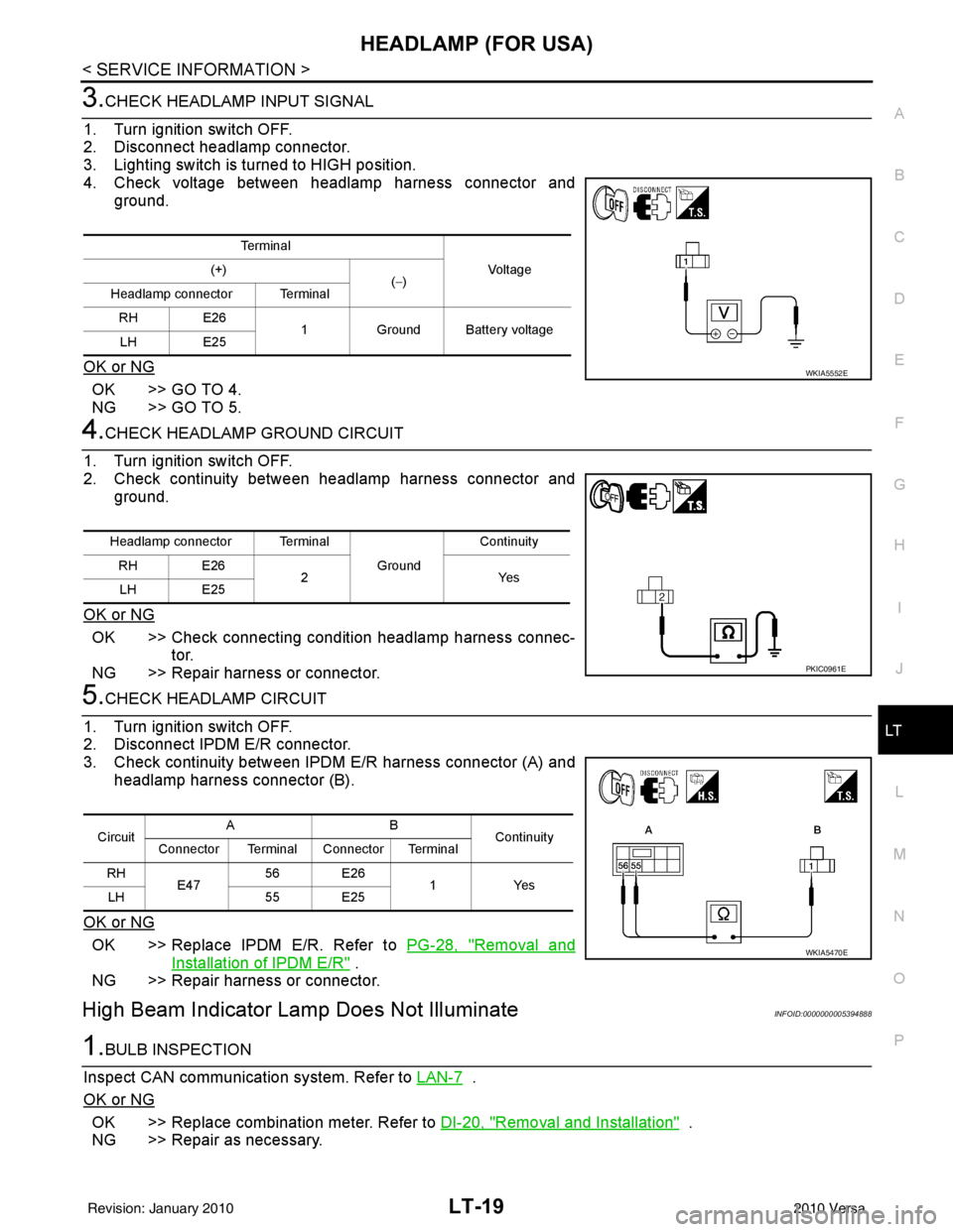
3.CHECK HEADLAMP INPUT SIGNAL
1. Turn ignition switch OFF.
2. Disconnect headlamp connector.
3. Lighting switch is turned to HIGH position.
4. Check voltage between headlamp harness connector and ground.
OK or NG
OK >> GO TO 4.
NG >> GO TO 5.
4.CHECK HEADLAMP GROUND CIRCUIT
1. Turn ignition switch OFF.
2. Check continuity between headlamp harness connector and ground.
OK or NG
OK >> Check connecting condition headlamp harness connec- tor.
NG >> Repair harness or connector.
5.CHECK HEADLAMP CIRCUIT
1. Turn ignition switch OFF.
2. Disconnect IPDM E/R connector.
3. Check continuity between IPDM E/R harness connector (A) and headlamp harness connector (B).
OK or NG
OK >> Replace IPDM E/R. Refer to PG-28, "Removal and
Installation of IPDM E/R" .
NG >> Repair harness or connector.
High Beam Indicator Lamp Does Not IlluminateINFOID:0000000005394888
1.BULB INSPECTION
Inspect CAN communication system. Refer to LAN-7
.
OK or NG
OK >> Replace combination meter. Refer to DI-20, "Removal and Installation" .
NG >> Repair as necessary.
Te r m i n a l
Vo l ta g e
(+)
(−)
Headlamp connector Terminal
RH E26 1Ground Battery voltage
LH E25
WKIA5552E
Headlamp connector Terminal
Ground Continuity
RH E26 2Y es
LH E25
PKIC0961E
Circuit AB
Continuity
Connector Terminal Connector Terminal
RH E47 56 E26
1Yes
LH 55 E25
WKIA5470E
Revision: January 20102010 Versa
Page 3018 of 3745

HEADLAMP (FOR USA)LT-23
< SERVICE INFORMATION >
C
DE
F
G H
I
J
L
M A
B
LT
N
O P
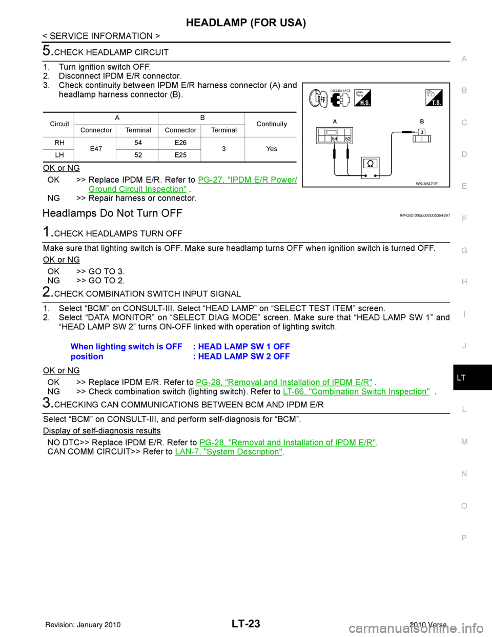
5.CHECK HEADLAMP CIRCUIT
1. Turn ignition switch OFF.
2. Disconnect IPDM E/R connector.
3. Check continuity between IPDM E/R harness connector (A) and headlamp harness connector (B).
OK or NG
OK >> Replace IPDM E/R. Refer to PG-27, "IPDM E/R Power/
Ground Circuit Inspection" .
NG >> Repair harness or connector.
Headlamps Do Not Turn OFFINFOID:0000000005394891
1.CHECK HEADLAMPS TURN OFF
Make sure that lighting switch is OFF. Make sure headlamp turns OFF when ignition switch is turned OFF.
OK or NG
OK >> GO TO 3.
NG >> GO TO 2.
2.CHECK COMBINATION SWITCH INPUT SIGNAL
1. Select “BCM” on CONSULT-III. Select “HEAD LAMP” on “SELECT TEST ITEM” screen.
2. Select “DATA MONITOR” on “SELECT DIAG MODE” screen. Make sure that “HEAD LAMP SW 1” and
“HEAD LAMP SW 2” turns ON-OFF li nked with operation of lighting switch.
OK or NG
OK >> Replace IPDM E/R. Refer to PG-28, "Removal and Installation of IPDM E/R" .
NG >> Check combination switch (lighting switch). Refer to LT-66, "
Combination Switch Inspection" .
3.CHECKING CAN COMMUNICATIONS BETWEEN BCM AND IPDM E/R
Select “BCM” on CONSULT-III, and perform self-diagnosis for “BCM”.
Display of self
-diagnosis results
NO DTC>> Replace IPDM E/R. Refer to PG-28, "Removal and Installation of IPDM E/R".
CAN COMM CIRCUIT>> Refer to LAN-7, "
System Description".
CircuitAB
Continuity
Connector Terminal Connector Terminal
RH E47 54 E26
3Yes
LH 52 E25
WKIA5471E
When lighting switch is OFF
position : HEAD LAMP SW 1 OFF
: HEAD LAMP SW 2 OFF
Revision: January 20102010 Versa