Page 3025 of 3745
LT-30
< SERVICE INFORMATION >
HEADLAMP (FOR CANADA) - DAYTIME LIGHT SYSTEM -
• to IPDM E/R terminal 56,
• through 10A fuse (No. 34, located in IPDM E/R) and
• through both de-energized headlamp high relays
• to 10A fuse (No. 35, located in IPDM E/R),
• through IPDM E/R terminal 55
• to front combination lamp LH terminal high beam 1.
Ground is supplied
• to front combination lamp LH terminal 2
• through grounds E15 and E24,
• to daytime light relay 1 terminal 1
• through IPDM E/R terminal 6.
With power and ground supplied, high beam headlamps illuminate at reduced intensity.
COMBINATION SWITCH READING FUNCTION
Refer to BCS-4, "System Description" .
EXTERIOR LAMP BATTERY SAVER CONTROL
Refer to LT-75, "System Description" .
CAN Communication System DescriptionINFOID:0000000005394898
Refer to LAN-7, "System Description" .
Revision: January 20102010 Versa
Page 3032 of 3745

HEADLAMP (FOR CANADA) - DAYTIME LIGHT SYSTEM -
LT-37
< SERVICE INFORMATION >
C
D E
F
G H
I
J
L
M A
B
LT
N
O P
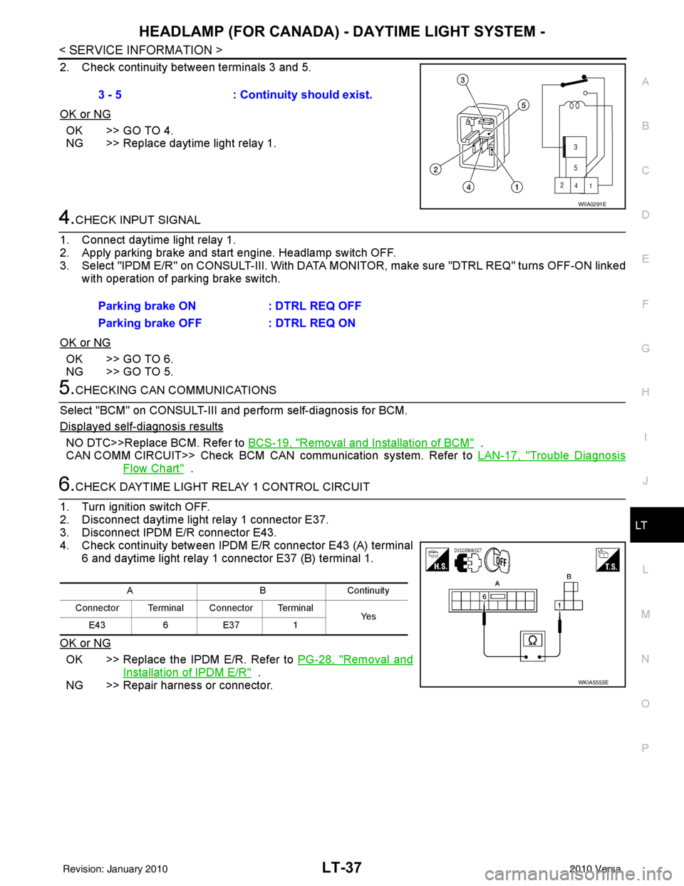
2. Check continuity between terminals 3 and 5.
OK or NG
OK >> GO TO 4.
NG >> Replace daytime light relay 1.
4.CHECK INPUT SIGNAL
1. Connect daytime light relay 1.
2. Apply parking brake and start engine. Headlamp switch OFF.
3. Select "IPDM E/R" on CONSULT-II I. With DATA MONITOR, make sure "DTRL REQ" turns OFF-ON linked
with operation of parking brake switch.
OK or NG
OK >> GO TO 6.
NG >> GO TO 5.
5.CHECKING CAN COMMUNICATIONS
Select "BCM" on CONSULT-III and perform self-diagnosis for BCM.
Displayed self-diagnosis results
NO DTC>>Replace BCM. Refer to BCS-19, "Removal and Installation of BCM" .
CAN COMM CIRCUIT>> Check BCM CAN communication system. Refer to LAN-17, "
Trouble Diagnosis
Flow Chart" .
6.CHECK DAYTIME LIGHT RELAY 1 CONTROL CIRCUIT
1. Turn ignition switch OFF.
2. Disconnect daytime light relay 1 connector E37.
3. Disconnect IPDM E/R connector E43.
4. Check continuity between IPDM E/R connector E43 (A) terminal 6 and daytime light relay 1 connector E37 (B) terminal 1.
OK or NG
OK >> Replace the IPDM E/R. Refer to PG-28, "Removal and
Installation of IPDM E/R" .
NG >> Repair harness or connector. 3 - 5
: Continuity should exist.
WIIA0291E
Parking brake ON : DTRL REQ OFF
Parking brake OFF : DTRL REQ ON
ABC ontin u it y
Connector Terminal Connector Terminal Ye s
E43 6E37 1
WKIA5553E
Revision: January 20102010 Versa
Page 3033 of 3745
LT-38
< SERVICE INFORMATION >
HEADLAMP (FOR CANADA) - DAYTIME LIGHT SYSTEM -
Aiming Adjustment
INFOID:0000000005394908
PREPARATION BEFORE ADJUSTING
Before performing aiming adjustment, check the following.
1. Keep all tires inflated to correct pressures.
2. Place vehicle on level surface.
3. Set that there is no-load in vehicle other than the driv er (or equivalent weight placed in driver's position).
Coolant, engine oil filled up to correct level and full fuel tank, spare tire, jack and tools are properly
stowed.
LOW BEAM AND HIGH BEAM
1. Turn headlamp low beam ON.
2. Use adjusting screw to perform aiming adjustment.
3. Insert the tool through the adjusting screw access hole to avoid damage to the adjusting screw.
ADJUSTMENT USING AN ADJUSTMENT SCREEN (LIGHT/DARK BORDERLINE)
1. Headlamp A. Inner and outer adjustment B. Adjusting screw access hole
C. Adjusting screw
LKIA0930E
Revision: January 20102010 Versa
Page 3038 of 3745
FRONT FOG LAMPLT-43
< SERVICE INFORMATION >
C
DE
F
G H
I
J
L
M A
B
LT
N
O P
• through IPDM E/R terminal 50
• to front fog lamp LH terminal 1, and
• through IPDM E/R terminal 51
• to front fog lamp RH terminal 1.
Ground is supplied
• to front fog lamp terminal 2,
• through grounds E15 and E24.
With power and grounds supplied, front fog lamps illuminate.
COMBINATION SWITCH READING FUNCTION
Refer to BCS-4, "System Description" .
EXTERIOR LAMP BATTERY SAVER CONTROL
Refer to LT-75, "System Description" .
CAN Communication System DescriptionINFOID:0000000005394914
Refer to LAN-7, "System Description" .
Revision: January 20102010 Versa
Page 3048 of 3745

TURN SIGNAL AND HAZARD WARNING LAMPSLT-53
< SERVICE INFORMATION >
C
DE
F
G H
I
J
L
M A
B
LT
N
O P
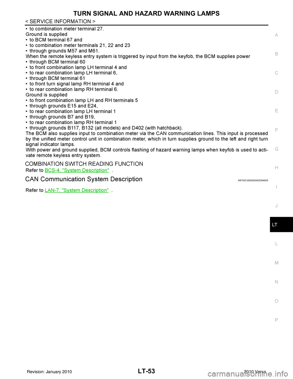
• to combination meter terminal 27.
Ground is supplied
• to BCM terminal 67 and
• to combination meter terminals 21, 22 and 23
• through grounds M57 and M61.
When the remote keyless entry system is triggered by input from the keyfob, the BCM supplies power
• through BCM terminal 60
• to front combination lamp LH terminal 4 and
• to rear combination lamp LH terminal 6,
• through BCM terminal 61
• to front turn signal lamp RH terminal 4 and
• to rear combination lamp RH terminal 6.
Ground is supplied
• to front combination lamp LH and RH terminals 5
• through grounds E15 and E24,
• to rear combination lamp LH terminal 1
• through grounds B7 and B19,
• to rear combination lamp RH terminal 1
• through grounds B117, B132 (all models) and D402 (with hatchback).
The BCM also supplies input to combination meter via the CAN communication lines. This input is processed
by the unified meter control unit in combination meter, which in turn supplies ground to the left and right turn
signal indicator lamps.
With power and ground supplied, BCM controls flashing of hazard warning lamps when keyfob is used to acti-
vate remote keyless entry system.
COMBINATION SWITCH READING FUNCTION
Refer to BCS-4, "System Description" .
CAN Communication System DescriptionINFOID:0000000005394929
Refer to LAN-7, "System Description" .
Revision: January 20102010 Versa
Page 3057 of 3745

LT-62
< SERVICE INFORMATION >
TURN SIGNAL AND HAZARD WARNING LAMPS
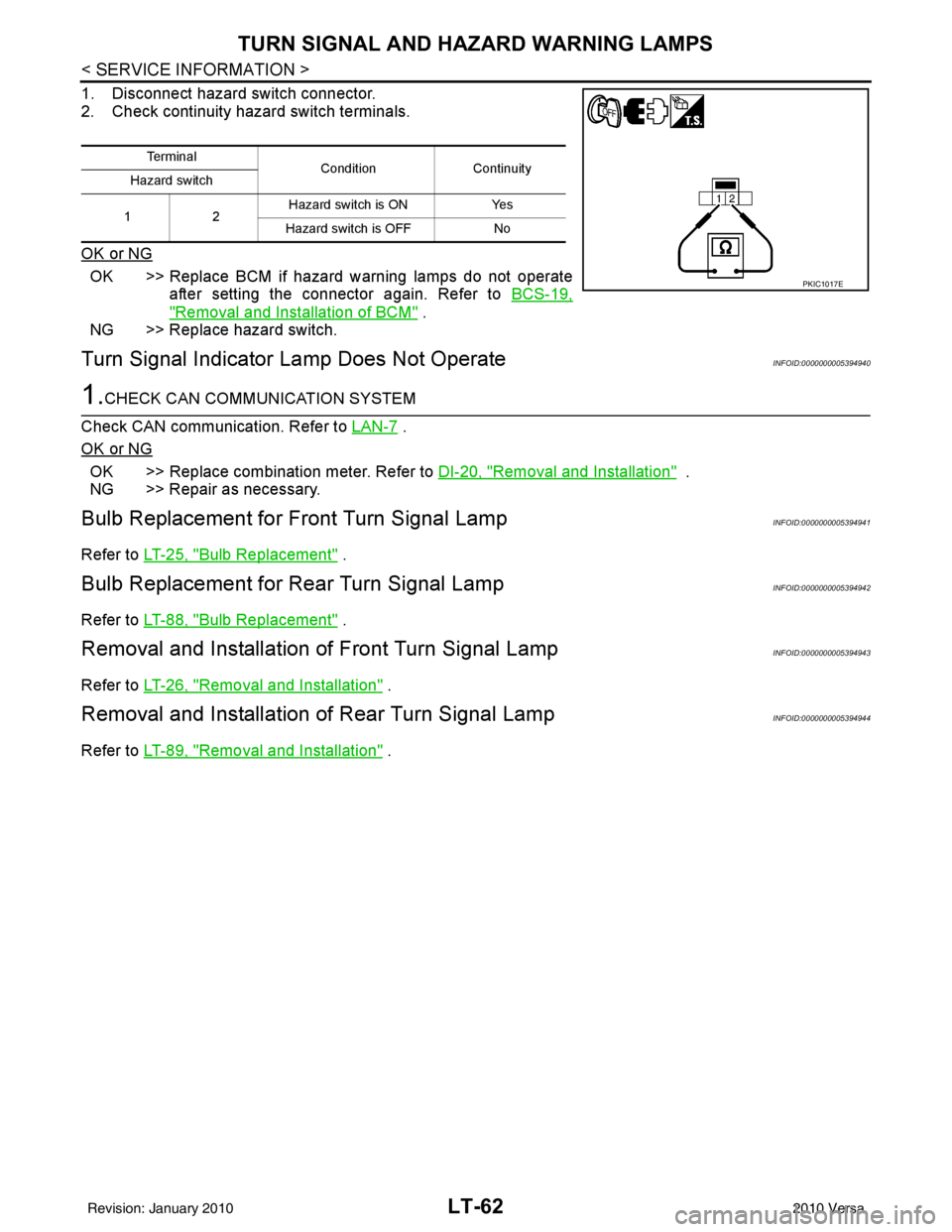
1. Disconnect hazard switch connector.
2. Check continuity hazard switch terminals.
OK or NG
OK >> Replace BCM if hazard warning lamps do not operateafter setting the connector again. Refer to BCS-19,
"Removal and Installation of BCM" .
NG >> Replace hazard switch.
Turn Signal Indicator Lamp Does Not OperateINFOID:0000000005394940
1.CHECK CAN COMMUNICATION SYSTEM
Check CAN communication. Refer to LAN-7
.
OK or NG
OK >> Replace combination meter. Refer to DI-20, "Removal and Installation" .
NG >> Repair as necessary.
Bulb Replacement for Front Turn Signal LampINFOID:0000000005394941
Refer to LT-25, "Bulb Replacement" .
Bulb Replacement for Rear Turn Signal LampINFOID:0000000005394942
Refer to LT-88, "Bulb Replacement" .
Removal and Installation of Front Turn Signal LampINFOID:0000000005394943
Refer to LT-26, "Removal and Installation" .
Removal and Installation of Rear Turn Signal LampINFOID:0000000005394944
Refer to LT-89, "Removal and Installation" .
Te r m i n a l
Condition Continuity
Hazard switch
12 Hazard switch is ON
Yes
Hazard switch is OFF No
PKIC1017E
Revision: January 20102010 Versa
Page 3071 of 3745

LT-76
< SERVICE INFORMATION >
PARKING, LICENSE PLATE AND TAIL LAMPS
• to front combination lamp RH terminal 6,
• through IPDM E/R terminal 28
• to rear combination lamp LH terminal 4 and
• to license plate lamp LH and RH terminal 1,
• through IPDM E/R terminal 29
• to rear combination lamp RH terminal 4.
Ground is supplied
• to front combination lamp LH and RH terminal 7
• through grounds E15 and E24,
• to rear combination lamp LH terminal 1 and
• to license plate lamp LH and RH terminal 2
• through grounds B7 and B19, and
• to rear combination lamp RH terminal 1
• through grounds B117, B132 (all models) and D402 (with hatchback).
With power and ground supplied, parking, license plate and tail lamps illuminate.
COMBINATION SWITCH READING FUNCTION
Refer to BCS-4, "System Description" .
EXTERIOR LAMP BATTERY SAVER CONTROL
When the combination switch (lighting switch) is in the 1ST (or 2ND) position and the ignition switch is turned
from ON or ACC to OFF, the battery saver control feature is activated.
Under this condition, the parking, license and tail la mps remain illuminated for 5 minutes, then the parking,
license plate and tail lamps are turned off.
Exterior lamp battery saver control mode can be changed by the function setting of CONSULT-III.
CAN Communication System DescriptionINFOID:0000000005394965
Refer to LAN-7, "System Description" .
Revision: January 20102010 Versa
Page 3106 of 3745
ILLUMINATIONLT-111
< SERVICE INFORMATION >
C
DE
F
G H
I
J
L
M A
B
LT
N
O P
• to hazard switch terminal 4
• to combination meter terminal 13
• to door mirror remote control switch terminal 15
• to combination switch (spiral cable) terminal 27 (with steering wheel audio control switches)
• to steering wheel audio control switches through combinat ion switch (spiral cable) terminal 21 (with steering
wheel audio control switches).
With power and ground supplied, illumination lamps illuminate.
EXTERIOR LAMP BATTERY SAVER CONTROL
Refer to LT-75, "System Description".
CAN Communication System DescriptionINFOID:0000000005394999
Refer to LAN-7, "System Description" .
Revision: January 20102010 Versa