2010 NISSAN LATIO ESP
[x] Cancel search: ESPPage 361 of 3745
AT-344
< SERVICE INFORMATION >
ASSEMBLY
ASSEMBLY
Assembly (1)INFOID:0000000005397449
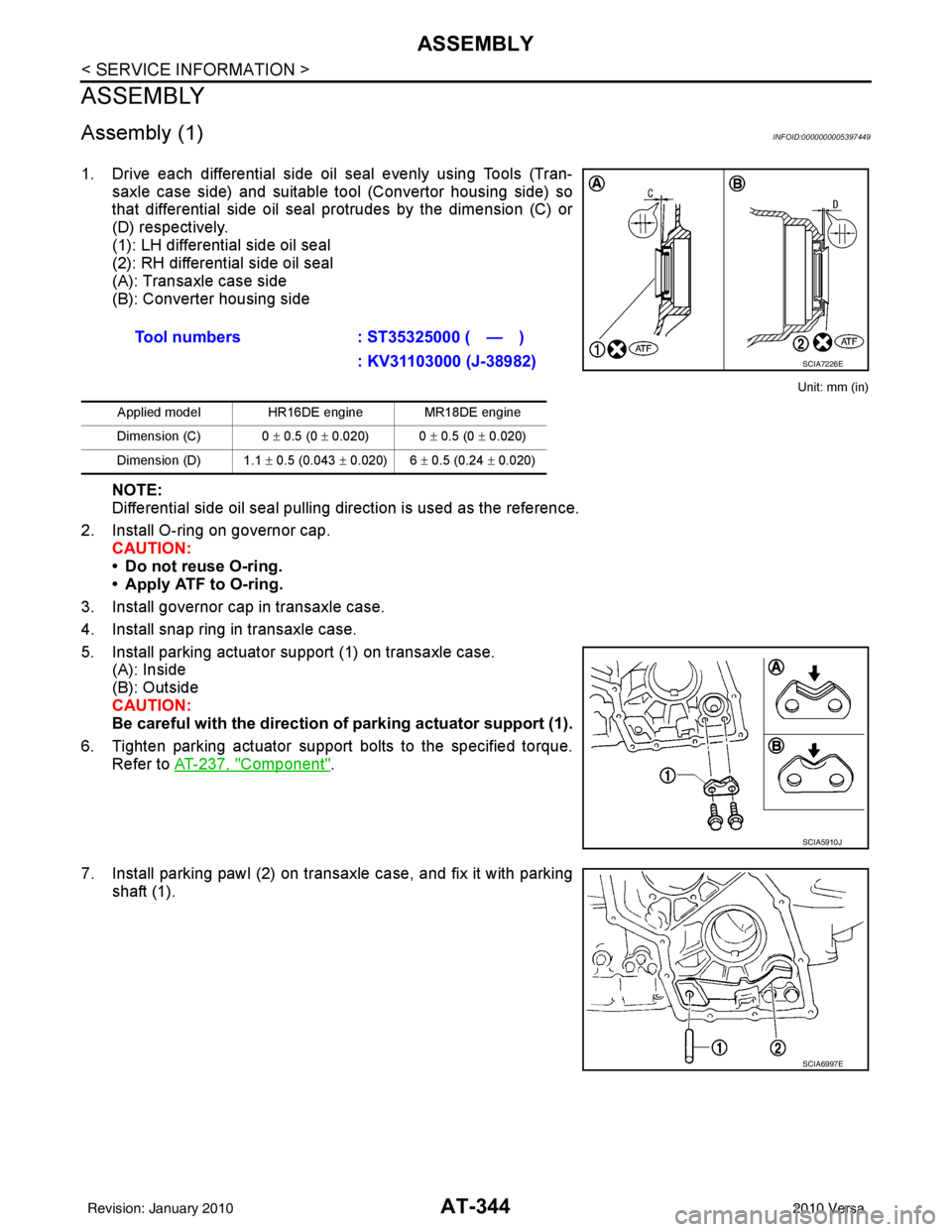
1. Drive each differential side oil seal evenly using Tools (Tran-saxle case side) and suitable tool (Convertor housing side) so
that differential side oil seal protrudes by the dimension (C) or
(D) respectively.
(1): LH differential side oil seal
(2): RH differential side oil seal
(A): Transaxle case side
(B): Converter housing side
Unit: mm (in)
NOTE:
Differential side oil seal pulling direction is used as the reference.
2. Install O-ring on governor cap. CAUTION:
• Do not reuse O-ring.
• Apply ATF to O-ring.
3. Install governor cap in transaxle case.
4. Install snap ring in transaxle case.
5. Install parking actuator support (1) on transaxle case. (A): Inside
(B): Outside
CAUTION:
Be careful with the direction of parking actuator support (1).
6. Tighten parking actuator support bolts to the specified torque. Refer to AT-237, "
Component".
7. Install parking pawl (2) on transaxle case, and fix it with parking shaft (1).Tool numbers
: ST35325000 ( — )
: KV31103000 (J-38982)
Applied model HR16DE engine MR18DE engine
Dimension (C) 0 ± 0.5 (0 ± 0.020) 0 ± 0.5 (0 ± 0.020)
Dimension (D) 1.1 ± 0.5 (0.043 ± 0.020) 6 ± 0.5 (0.24 ± 0.020)
SCIA7226E
SCIA5910J
SCIA6997E
Revision: January 20102010 Versa
Page 418 of 3745
![NISSAN LATIO 2010 Service Repair Manual AUDIOAV-21
< SERVICE INFORMATION > [AUDIO WITHOUT NAVIGATION]
C
D
E
F
G H
I
J
L
M A
B
AV
N
O P
NOTE:
Noise resulting from variations in field strength, such as fading noise and multi-path noise, or e NISSAN LATIO 2010 Service Repair Manual AUDIOAV-21
< SERVICE INFORMATION > [AUDIO WITHOUT NAVIGATION]
C
D
E
F
G H
I
J
L
M A
B
AV
N
O P
NOTE:
Noise resulting from variations in field strength, such as fading noise and multi-path noise, or e](/manual-img/5/57358/w960_57358-417.png)
AUDIOAV-21
< SERVICE INFORMATION > [AUDIO WITHOUT NAVIGATION]
C
D
E
F
G H
I
J
L
M A
B
AV
N
O P
NOTE:
Noise resulting from variations in field strength, such as fading noise and multi-path noise, or external noise
from trains and other sources. It is not a malfunction.
• Fading noise: This noise occurs because of variations in the field strength in a narrow range due to moun-
tains or buildings blocking the signal.
• Multi-path noise: This noise results from the waves sent directly from the broadcast station arriving at the antenna at a different time from the waves t hat reflect off of mountains or buildings.
Noise InspectionINFOID:0000000005395318
The vehicle itself can be a source of noise if noise prevention parts or electrical equipment is malfunctioning.
Check if noise is caused and/or changed by engine speed, ignition switch turned to each position, and opera-
tion of each piece of electrical equipment, and determine the cause.
NOTE:
The source of the noise can be found easily by listening to the noise while removing the fuses of electrical
components, one by one.
TYPE OF NOISE AND POSSIBLE CAUSE
No sound can be heard from one or several speakers. • Open or short in audio signal circuit between audio unit and front
speaker. Refer to AV- 2 4 , "
Sound Is Not Heard from Front Door
Speaker (Base System)" or AV- 2 6 , "Sound Is Not Heard from
Front Door Speaker or Tweeter (Premium System)" .
• Front speaker. Refer to AV- 2 4 , "
Sound Is Not Heard from Front
Door Speaker (Base System)" or AV- 2 6 , "Sound Is Not Heard
from Front Door Speaker or Tweeter (Premium System)" .
• Open or short in audio signal circuit between audio unit and rear
speaker. Refer to AV- 2 5 , "
Sound Is Not Heard from Rear Door
Speaker (Base System)" or AV- 2 7 , "Sound Is Not Heard from
Rear Door Speaker (Premium System)" .
• Rear speaker. Refer to AV- 2 5 , "
Sound Is Not Heard from Rear
Door Speaker (Base System)" or AV- 2 7 , "Sound Is Not Heard
from Rear Door Speaker (Premium System)" .
• Tweeter (mid level and premium system) AV- 2 6 , "
Sound Is Not
Heard from Front Door Speaker or Tweeter (Premium System)"
or AV- 2 7 , "
Sound Is Not Heard from Rear Door Speaker (Premi-
um System)" .
• Audio unit. Refer to AV- 2 9 , "
Removal and Installation" .
No sound can be heard from radio or noise is heard. • Antenna feeder. Refer to
AV- 3 3
.
• Antenna. Refer to AV- 3 3
.
• Audio unit. Refer to AV- 2 9 , "
Removal and Installation" .
Symptom
Check item
Occurrence condition Possible cause
Occurs only when engine is ON. A continuous growling noise occurs. The speed of
the noise varies with changes in the engine speed.
Ignition components
A whistling noise occurs while the engine speed is
high. A booming noise occurs while the engine is
running and the lighting switch is ON. Generator
Noise only occurs when various
electrical components are oper-
ating. A cracking or snapping sound occurs with the op-
eration of various switches.
Relay malfunction, radio malfunction
The noise occurs when various motors are operat-
ing. • Motor case ground
•Motor
The noise occurs constantly, not just under certain conditions. • Rear defogger coil malfunction
• Open circuit in printed heater
A cracking or snapping sound occurs while the vehicle is being driven, especially when
it is vibrating excessively. • Ground wire of body parts.
• Ground due to improper part installation
• Wiring connections or a short circuit
Revision: January 20102010 Versa
Page 459 of 3745
![NISSAN LATIO 2010 Service Repair Manual AV-62
< SERVICE INFORMATION >[AUDIO WITH NAVIGATION]
AUDIO
On-Board Diagnosis
INFOID:0000000005988546
METHOD OF STARTING
1. Start the engine.
2. Turn OFF audio.
3. While pressing the “SET UP” s wi NISSAN LATIO 2010 Service Repair Manual AV-62
< SERVICE INFORMATION >[AUDIO WITH NAVIGATION]
AUDIO
On-Board Diagnosis
INFOID:0000000005988546
METHOD OF STARTING
1. Start the engine.
2. Turn OFF audio.
3. While pressing the “SET UP” s wi](/manual-img/5/57358/w960_57358-458.png)
AV-62
< SERVICE INFORMATION >[AUDIO WITH NAVIGATION]
AUDIO
On-Board Diagnosis
INFOID:0000000005988546
METHOD OF STARTING
1. Start the engine.
2. Turn OFF audio.
3. While pressing the “SET UP” s witch, turn the MENU dial coun-
terclockwise 3 clicks or more first, then clockwise and counter-
clockwise 3 clicks or more, respectively. (After the diagnosis
mode starts, the initial screen of the diagnosis mode appears.)
• On-board diagnosis can be performed in the service test mode.
• On-board diagnosis checks that the system can be operated normally.
Service test mode
46 (L) — AUX sound
signal LH—— —
——
47 (W) — USB D- — — —— —
48 (GR) — AUX sound
signal RH—— —
——
49 (G) — USB D+ — — —— —
50 (BR) — AUX sound
signal
ground—— —
——
51 (R) — USB V BUS
signal—— —
——
53 (GR) — SHIELD — — —— —
54 — Satellite an-
tenna signal
—— —
——
55 — GPS anten-
na signal—— —
——
56 — SHIELD — — —— —
57 — Antenna on
signal—— —
——
58 — Main anten-
na signal
—— —
——
Te r m i n a l
(Wire color) ItemSignal
input/
output Condition
Reference value
(Approx.) Example of symp-
tom
+– Ignition
switch Operation
JSNIA2456ZZ
Mode
ItemContent
Service version —The version data of the parts is shown
displayed.
Revision: January 20102010 Versa
Page 461 of 3745
![NISSAN LATIO 2010 Service Repair Manual AV-64
< SERVICE INFORMATION >[AUDIO WITH NAVIGATION]
AUDIO
System stateRunning system status
• SD card slot Access
• Power Supply
• Speed Signal
• Direction Signal
• Illumination Signal
• NISSAN LATIO 2010 Service Repair Manual AV-64
< SERVICE INFORMATION >[AUDIO WITH NAVIGATION]
AUDIO
System stateRunning system status
• SD card slot Access
• Power Supply
• Speed Signal
• Direction Signal
• Illumination Signal
•](/manual-img/5/57358/w960_57358-460.png)
AV-64
< SERVICE INFORMATION >[AUDIO WITH NAVIGATION]
AUDIO
System stateRunning system status
• SD card slot Access
• Power Supply
• Speed Signal
• Direction Signal
• Illumination Signal
• GPS Antenna
• EXT. Phone Sig
• Microphone Current
• Radio Antenna
• USB Device
•iPod
® firmware version
• Steering wheel X11C The current system status is dis-
played.
System history •Bluetooth
® Module - Sub-Unit
Connection Malfunction
• SD-card Slot - Sub-Unit Connec- tion Malfunction
• Programming Error
• Radio-Antenna Circuit Malfunc- tion
• FM-Antenna 1 Connection Mal- function
• Satellite Antenna Connection
Failure
• GPS Antenna Circuit Malfunc- tion
• CD-Drive Mechanical Malfunc- tion
• CD Read Malfunction
• Power Supply voltage: Lower
Limit Exceeded
• Power Supply voltage: Upper
Limit Exceeded
• Reduced system Functionality due to over temperature
• Display switched OFF due to over temperature
• SD card removed without being de-mounted
• Code plug missing The history of the system status is re-
ported in the report memory, dis-
played.
Speaker test 100Hz —This activates a sequence of test tone
outputs to the four speaker lines one
after the other for 1 second.
The frequency can be chosen by user
selection (100Hz and 4KHz).
Speaker test 4KHz
Display test —This provides a test sequence where
test displays (plain colored display:
e.g. white, black, red, blue, green) are
shown one after the other.
The respective color is shown for an
indicated period of time (parameter).
After the display test, the design of the
display previously available is stored.
While the screen shows a plain col-
ored display, a pixel malfunction may
be detected.
Mode
ItemContent
Revision: January 20102010 Versa
Page 493 of 3745
BCS-4
< SERVICE INFORMATION >
BCM (BODY CONTROL MODULE)
BCM (BODY CONTROL MODULE)
System DescriptionINFOID:0000000005395103
BCM (body control module) controls the operation of various electrical units installed on the vehicle.
BCM FUNCTION
BCM has a combination switch reading function for reading the operation of combination switches (light, wiper,
washer, turn signal) in addition to the function for cont rolling the operation of various electrical components.
Also, it functions as an interface that receives signal s from the front air control, and sends signals to ECM
using CAN communication.
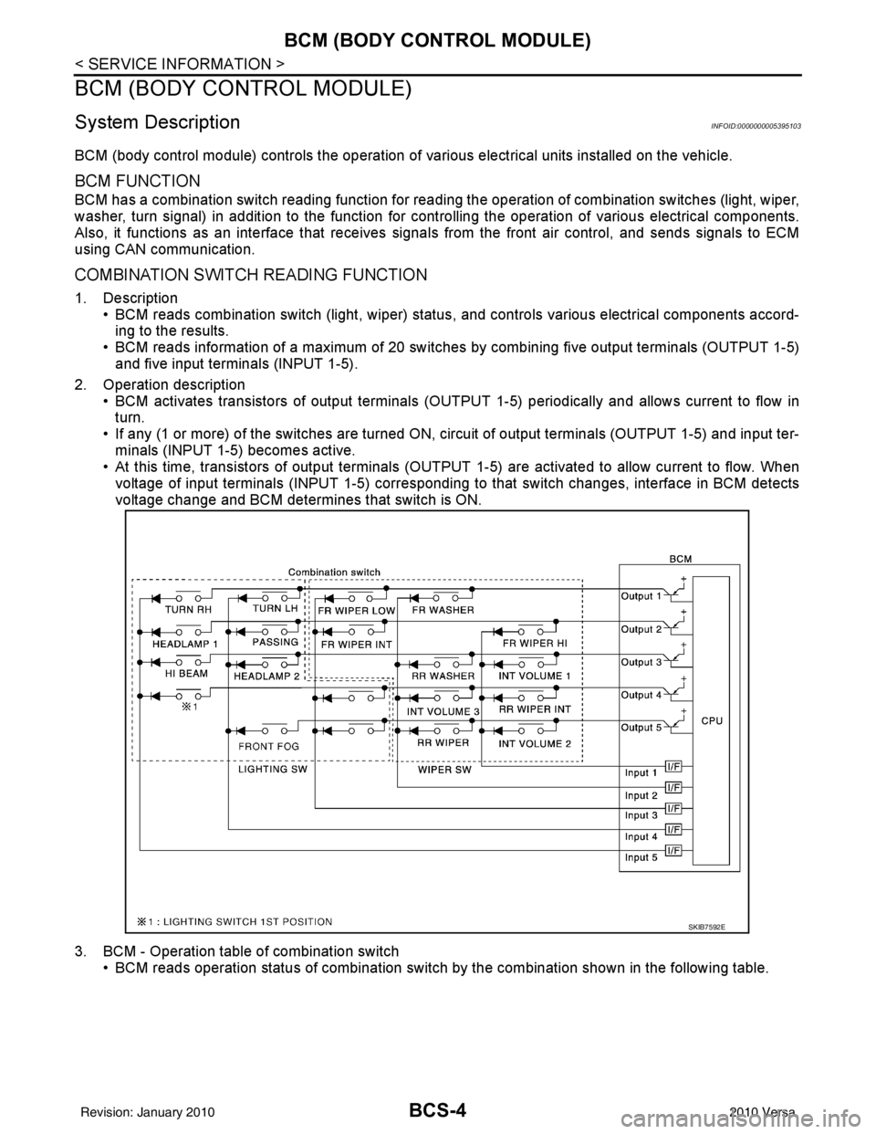
COMBINATION SWITCH READING FUNCTION
1. Description • BCM reads combination switch (light, wiper) status, and controls various electrical components accord-
ing to the results.
• BCM reads information of a maximum of 20 switches by combining five output terminals (OUTPUT 1-5)
and five input terminals (INPUT 1-5).
2. Operation description • BCM activates transistors of output terminals (OUTPU T 1-5) periodically and allows current to flow in
turn.
• If any (1 or more) of the switches are turned ON, circuit of output terminals (OUTPUT 1-5) and input ter- minals (INPUT 1-5) becomes active.
• At this time, transistors of output terminals (OUTPUT 1-5) are activated to allow current to flow. When
voltage of input terminals (INPUT 1-5) corresponding to that switch changes, interface in BCM detects
voltage change and BCM determines that switch is ON.
3. BCM - Operation table of combination switch • BCM reads operation status of combination switch by the combination shown in the following table.
SKIB7592E
Revision: January 20102010 Versa
Page 516 of 3745
SQUEAK AND RATTLE TROUBLE DIAGNOSESBL-7
< SERVICE INFORMATION >
C
DE
F
G H
J
K L
M A
B
BL
N
O P
SQUEAK AND RATTLE TROUBLE DIAGNOSES
Work FlowINFOID:0000000005396544
CUSTOMER INTERVIEW
Interview the customer if possible, to determine the conditions that exist when the noise occurs. Use the Diag-
nostic Worksheet during the interv iew to document the facts and conditions when the noise occurs and any
customer's comments; refer to BL-11, "
Diagnostic Worksheet". This information is necessary to duplicate the
conditions that exist when the noise occurs.
• The customer may not be able to provide a detailed descr iption or the location of the noise. Attempt to obtain
all the facts and conditions that exist when the noise occurs (or does not occur).
• If there is more than one noise in the vehicle, be sure to diagnose and repair the noise that the customer is
concerned about. This can be accomplished by test driving the vehicle with the customer.
• After identifying the type of noise, isolate the noise in terms of its characteristics. The noise characteristics
are provided so the customer, service adviser and technician are all speaking the same language when
defining the noise.
• Squeak —(Like tennis shoes on a clean floor)
Squeak characteristics include the light contact/fast movement/brought on by road conditions/hard surfaces
= higher pitch noise/softer surfaces = lower pitch noises/edge to surface = chirping.
• Creak—(Like walking on an old wooden floor)
Creak characteristics include firm contact/slow mo vement/twisting with a rotational movement/pitch depen-
dent on materials/often brought on by activity.
• Rattle—(Like shaking a baby rattle)
Rattle characteristics include the fast repeated contac t/vibration or similar movement/loose parts/missing
clip or fastener/incorrect clearance.
• Knock —(Like a knock on a door)
Knock characteristics include hollow sounding/someti mes repeating/often brought on by driver action.
• Tick—(Like a clock second hand) Tick characteristics include gentle contacting of li ght materials/loose components/can be caused by driver
action or road conditions.
• Thump—(Heavy, muffled knock noise) Thump characteristics include softer k nock/dead sound often brought on by activity.
• Buzz—(Like a bumble bee)
Buzz characteristics include high frequency rattle/firm contact.
• Often the degree of acceptable noise level will vary depending upon the person. A noise that you may judge as acceptable may be very irritating to the customer.
• Weather conditions, especially humidity and temperature, may have a great effect on noise level.
DUPLICATE THE NOISE AND TEST DRIVE
If possible, drive the vehicle with the customer until the noise is duplicated. Note any additional information on
the Diagnostic Worksheet regarding the conditions or lo cation of the noise. This information can be used to
duplicate the same conditions when you confirm the repair.
SBT842
Revision: January 20102010 Versa
Page 582 of 3745
REMOTE KEYLESS ENTRY SYSTEMBL-73
< SERVICE INFORMATION >
C
DE
F
G H
J
K L
M A
B
BL
N
O P
With CONSULT-III
Check keyfob function in “DATA MONITOR” mode with CONSULT-III. When pushing each button of keyfob,
the corresponding monitor item should be turned as follows.
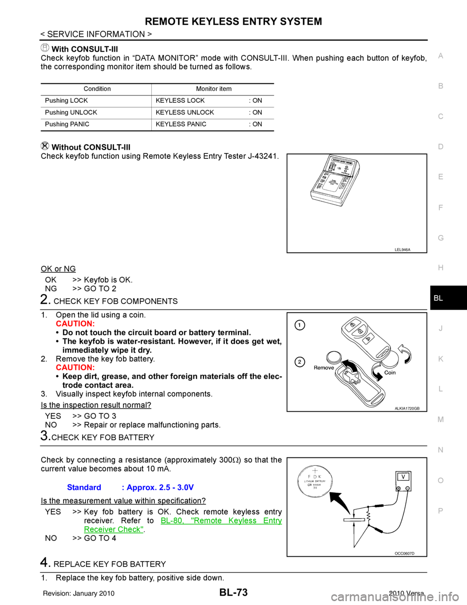
Without CONSULT-III
Check keyfob function using Remote Keyless Entry Tester J-43241.
OK or NG
OK >> Keyfob is OK.
NG >> GO TO 2
2. CHECK KEY FOB COMPONENTS
1. Open the lid using a coin. CAUTION:
• Do not touch the circuit board or battery terminal.
• The keyfob is water-resistant. However, if it does get wet,immediately wipe it dry.
2. Remove the key fob battery. CAUTION:
• Keep dirt, grease, and other fo reign materials off the elec-
trode contact area.
3. Visually inspect keyfob internal components.
Is the inspection result normal?
YES >> GO TO 3
NO >> Repair or replace malfunctioning parts.
3.CHECK KEY FOB BATTERY
Check by connecting a resistance (approximately 300 Ω) so that the
current value becomes about 10 mA.
Is the measurement val ue within specification?
YES >> Key fob battery is OK. Check remote keyless entry
receiver. Refer to BL-80, "
Remote Keyless Entry
Receiver Check".
NO >> GO TO 4
4. REPLACE KEY FOB BATTERY
1. Replace the key fob battery, positive side down.
Condition Monitor item
Pushing LOCK KEYLESS LOCK: ON
Pushing UNLOCK KEYLESS UNLOCK: ON
Pushing PANIC KEYLESS PANIC: ON
LEL946A
ALKIA1720GB
Standard : Approx. 2.5 - 3.0V
OCC0607D
Revision: January 20102010 Versa
Page 591 of 3745
BL-82
< SERVICE INFORMATION >
REMOTE KEYLESS ENTRY SYSTEM
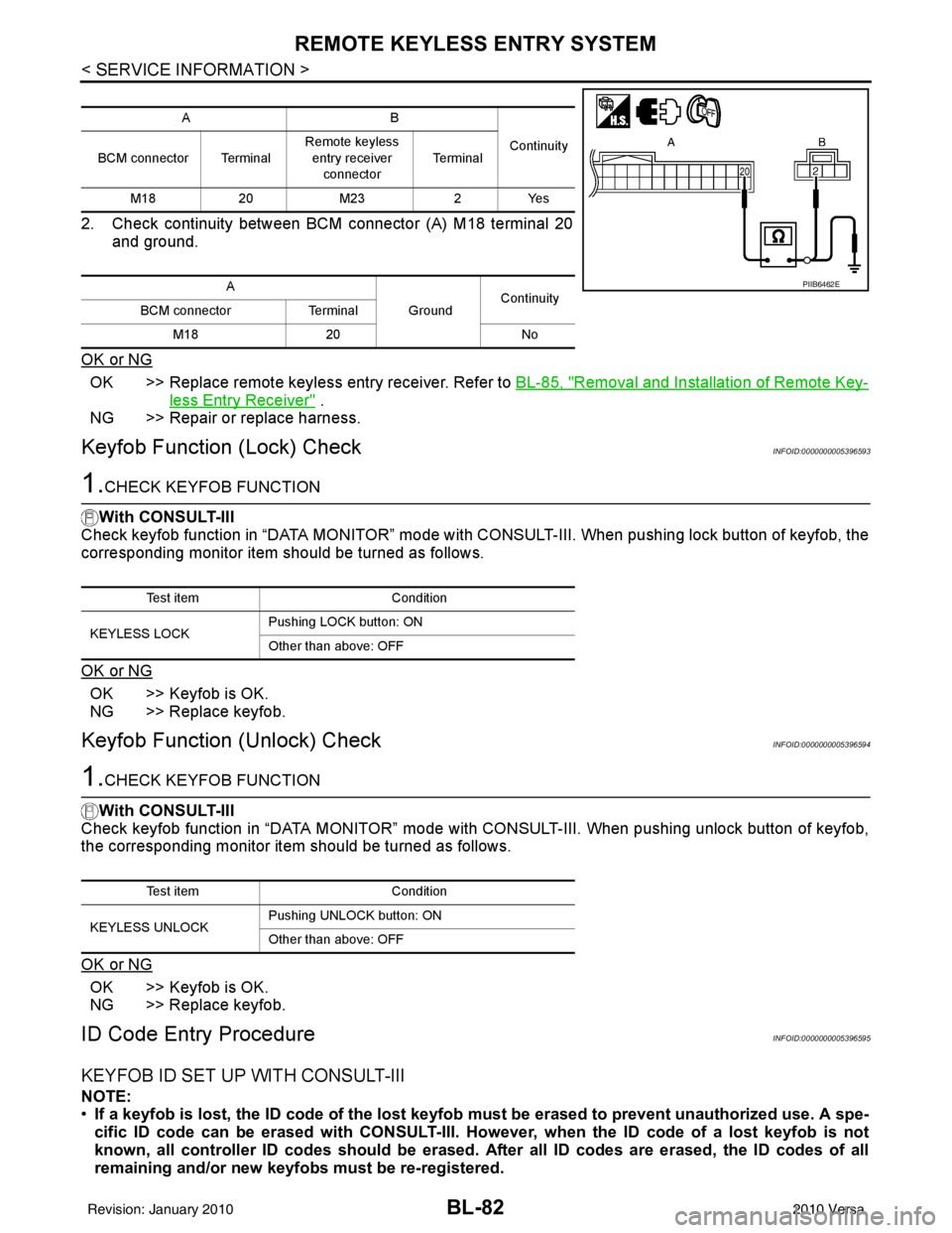
2. Check continuity between BCM connector (A) M18 terminal 20and ground.
OK or NG
OK >> Replace remote keyless entry receiver. Refer to BL-85, "Removal and Installation of Remote Key-
less Entry Receiver" .
NG >> Repair or replace harness.
Keyfob Function (Lock) CheckINFOID:0000000005396593
1.CHECK KEYFOB FUNCTION
With CONSULT-III
Check keyfob function in “DATA MONITOR” mode with CO NSULT-III. When pushing lock button of keyfob, the
corresponding monitor item should be turned as follows.
OK or NG
OK >> Keyfob is OK.
NG >> Replace keyfob.
Keyfob Function (Unlock) CheckINFOID:0000000005396594
1.CHECK KEYFOB FUNCTION
With CONSULT-III
Check keyfob function in “DATA MONITOR” mode with CONSULT-III. When pushing unlock button of keyfob,
the corresponding monitor item should be turned as follows.
OK or NG
OK >> Keyfob is OK.
NG >> Replace keyfob.
ID Code Entry ProcedureINFOID:0000000005396595
KEYFOB ID SET UP WITH CONSULT-III
NOTE:
• If a keyfob is lost, the ID code of the lost keyfob must be erased to prevent unauthorized use. A spe-
cific ID code can be erased with CONSULT-III. Ho wever, when the ID code of a lost keyfob is not
known, all controller ID codes should be erased. After all ID codes are erased, the ID codes of all
remaining and/or new keyfobs must be re-registered.
AB
Continuity
BCM connector Terminal Remote keyless
entry receiver
connector Te r m i n a l
M18 20M23 2Yes
A GroundContinuity
BCM connector Terminal
M18 20 No
PIIB6462E
Test item Condition
KEYLESS LOCK Pushing LOCK button: ON
Other than above: OFF
Test item
Condition
KEYLESS UNLOCK Pushing UNLOCK button: ON
Other than above: OFF
Revision: January 20102010 Versa