2010 NISSAN LATIO ESP
[x] Cancel search: ESPPage 140 of 3745

P0740 TORQUE CONVERTERAT-123
< SERVICE INFORMATION >
DE
F
G H
I
J
K L
M A
B
AT
N
O P
P0740 TORQUE CONVERTER
DescriptionINFOID:0000000005397310
• The torque converter clutch solenoid valve is activated, with the gear in D4 and D3, by the TCM in response
to signals sent from the output speed sensor and t he ECM (throttle opening). Lock-up piston operation will
then be controlled.
• Lock-up operation, however, is prohibited when A/T fluid temperature is too low.
• When the accelerator pedal is depressed (less than 2/8) on lock-up condition, the engine speed should not
change abruptly. If there is an abrupt change in engine speed, there is no lock-up.
CONSULT-III Reference Val ue in Data Monitor ModeINFOID:0000000005397311
Remarks: Specification data are reference values.
On Board Diagnosis LogicINFOID:0000000005397312
• This is an OBD-II self-diagnostic item.
• Diagnostic trouble code “P0740 T/C CLUTCH SOL” with CO NSULT-III or 7th judgement flicker without CON-
SULT-III is detected when TCM detects an improper vo ltage drop while it tries to operate solenoid valve.
Possible CauseINFOID:0000000005397313
• Torque converter clutch solenoid valve
• Harness or connector
(The solenoid circuit is open or shorted.)
DTC Confirmation ProcedureINFOID:0000000005397314
CAUTION:
• Always drive vehicle at a safe speed.
• If performing this “DTC Confirmation Procedure” again, always turn ignition switch OFF and wait at
least 10 seconds before continuing.
After the repair, perform the following procedure to confirm the malfunction is eliminated.
WITH CONSULT-III
1. Turn ignition switch ON. (Do not start engine.)
2. Select “DATA MONITOR” mode for “TRANSMISSION” with CONSULT-III and wait at least 1 second.
3. Touch “START”.
4. Start engine and maintain the following conditions for at least 5 consecutive seconds. VEHICLE SPEED: 80 km/h (50 MPH) or more
THROTTLE POSI: 0.5/8 - 1.0/8
SLCT LVR POSI: “D” position
Driving location: Driving the vehic le uphill (increased engine load) will help maintain the driving
conditions required for this test.
5. If the check result is NG, go to AT-125, "
Diagnosis Procedure".
WITH GST
Follow the procedure “WITH CONSULT-III”.
WITHOUT CONSULT-III
1. Start engine.
2. Drive vehicle in D
1→ D2→ D3→ D4→ D4 lock-up position.
3. Perform self-diagnosis. Refer to AT-82, "
Diagnosis Procedure without CONSULT-III" .
4. If the check result is NG, go to AT-125, "
Diagnosis Procedure" .
Item nameCondition Display value (Approx)
TCC S/V DUTY Lock-up OFF ⇔ Lock-up ON 4% ⇔ 94%
Revision: January 20102010 Versa
Page 150 of 3745

P0745 PRESSURE CONTROL SOLENOID AAT-133
< SERVICE INFORMATION >
DE
F
G H
I
J
K L
M A
B
AT
N
O P
P0745 PRESSURE CONTROL SOLENOID A
DescriptionINFOID:0000000005397324
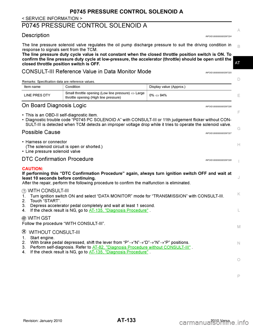
The line pressure solenoid valve regulates the oil pum p discharge pressure to suit the driving condition in
response to signals sent from the TCM.
The line pressure duty cycle value is not constant when the closed throttle po sition switch is ON. To
confirm the line pressure duty cycle at low-pressure, the accelerator (throttle) sh ould be open until the
closed throttle position switch is OFF.
CONSULT-III Reference Val ue in Data Monitor ModeINFOID:0000000005397325
Remarks: Specification data are reference values.
On Board Diagnosis LogicINFOID:0000000005397326
• This is an OBD-II self-diagnostic item.
• Diagnostic trouble code “P0745 PC SOLENOID A” with CO NSULT-III or 11th judgement flicker without CON-
SULT-III is detected when TCM detects an improper volt age drop while it tries to operate the solenoid valve.
Possible CauseINFOID:0000000005397327
• Harness or connector
(The solenoid circuit is open or shorted.)
• Line pressure solenoid valve
DTC Confirmation ProcedureINFOID:0000000005397328
CAUTION:
If performing this “DTC Confirmati on Procedure” again, always turn ignition switch OFF and wait at
least 10 seconds before continuing.
After the repair, perform the following procedure to confirm the malfunction is eliminated.
WITH CONSULT-III
1. Turn ignition switch ON and select “DATA MO NITOR” mode for “TRANSMISSION” with CONSULT-III.
2. Touch “START”.
3. Depress accelerator pedal completely and wait at least 1 second.
4. If the check result is NG, go to AT-135, "
Diagnosis Procedure" .
WITH GST
Follow the procedure “WITH CONSULT-III”.
WITHOUT CONSULT-III
1. Start engine.
2. With brake pedal depressed, shift the lever from “P” →“N” →“D” →“N” →“P” positions.
3. Perform self-diagnosis. Refer to AT-82, "
Diagnosis Procedure without CONSULT-III" .
4. If the check result is NG, go to AT-135, "
Diagnosis Procedure" .
Item nameCondition Display value (Approx.)
LINE PRES DTY Small throttle opening (Low line pressure)
⇔ Large
throttle opening (High line pressure) 0%
⇔ 94%
Revision: January 20102010 Versa
Page 155 of 3745

AT-138
< SERVICE INFORMATION >
P0750 SHIFT SOLENOID A
P0750 SHIFT SOLENOID A
DescriptionINFOID:0000000005397332
Shift solenoid valves A and B are turned ON or OFF by the TCM in response to signals sent from the transmis-
sion range switch, vehicle speed and ECM (throttle opening) . Gears will then be shifted to the optimum posi-
tion.
CONSULT-III Reference Value in Data Monitor ModeINFOID:0000000005397333
On Board Diagn osis LogicINFOID:0000000005397334
• This is an OBD-II self-diagnostic item.
• Diagnostic trouble code “P0750 SHIFT SOLENOID A” wi th CONSULT-III or 4th judgement flicker without
CONSULT-III is detected when TCM detects an improper voltage drop when it tries to operate the solenoid
valve.
Possible CauseINFOID:0000000005397335
• Harness or connector (The solenoid circuit is open or shorted.)
• Shift solenoid valve A
DTC Confirmation ProcedureINFOID:0000000005397336
CAUTION:
• Always drive vehicle at a safe speed.
• If performing this “DTC Confirmation Procedure” again, always turn ignition switch OFF and wait at
least 10 seconds before continuing.
After the repair, perform the following proc edure to confirm the malfunction is eliminated.
WITH CONSULT-III
1. Turn ignition switch ON and select “DATA MONI TOR” mode for “TRANSMISSION” with CONSULT-III.
2. Touch “START”.
3. Start engine.
4. Drive vehicle in “D” position and allow the transaxle to shift 1 → 2 (“GEAR”).
5. If the check result is NG, go to AT-140, "
Diagnosis Procedure" .
WITH GST
Follow the procedure “WITH CONSULT-III”.
WITHOUT CONSULT-III
1. Start engine.
2. Drive vehicle in D
1→ D2 position.
3. Perform self-diagnosis. Refer to AT-82, "
Diagnosis Procedure without CONSULT-III" .
4. If the check result is NG, go to AT-140, "
Diagnosis Procedure" .
Gea r p osit io n1234
Shift solenoid valve A ON (Closed)OFF (Open)OFF (Open)ON (Closed)
Shift solenoid valve B ON (Closed)ON (Closed) OFF (Open)OFF (Open)
Item name Condition Display value
SHIFT S/V A When shift solenoid valve A operates.
(When driving in “D
1 ” or “D4 ”.)
ON
When shift solenoid valve A does not operate.
(When driving in “D
2 ” or “D3 ”.) OFF
Revision: January 20102010 Versa
Page 160 of 3745

P0755 SHIFT SOLENOID BAT-143
< SERVICE INFORMATION >
DE
F
G H
I
J
K L
M A
B
AT
N
O P
P0755 SHIFT SOLENOID B
DescriptionINFOID:0000000005397340
Shift solenoid valves A and B are turned ON or OFF by the TCM in response to signals sent from the transmis-
sion range switch, vehicle speed and ECM (throttle openi ng). Gears will then be shifted to the optimum posi-
tion.
CONSULT-III Reference Val ue in Data Monitor ModeINFOID:0000000005397341
On Board Diagnosis LogicINFOID:0000000005397342
• This is an OBD-II self-diagnostic item.
• Diagnostic trouble code “P0755 SHIFT SOLENOID B” with CONSULT-III or 5th judgement flicker without
CONSULT-III is detected when TCM detects an improper voltage drop when it tries to operate the solenoid
valve.
Possible CauseINFOID:0000000005397343
• Harness or connector
(The solenoid circuit is open or shorted.)
• Shift solenoid valve B
DTC Confirmation ProcedureINFOID:0000000005397344
CAUTION:
• Always drive vehicle at a safe speed.
• If performing this “DTC Confirmation Procedure” again, always turn ignition switch OFF and wait at
least 10 seconds before continuing.
After the repair, perform the following procedure to confirm the malfunction is eliminated.
WITH CONSULT-III
1. Turn ignition switch ON and select “DATA MO NITOR” mode for “TRANSMISSION” with CONSULT-III.
2. Touch “START”.
3. Start engine.
4. Drive vehicle in D position and allow the transaxle to shift 1 → 2 → 3 (“GEAR”).
5. If the check result is NG, go to AT-145, "
Diagnosis Procedure" .
WITH GST
Follow the procedure “WITH CONSULT-III”.
WITHOUT CONSULT-III
1. Start engine.
2. Drive vehicle in D
1→ D2→ D3 position.
3. Perform self-diagnosis. Refer to AT-82, "
Diagnosis Procedure without CONSULT-III" .
4. If the check result is NG, go to AT-145, "
Diagnosis Procedure" .
Gear position 123 4
Shift solenoid valve A ON (Closed)OFF (Open)OFF (Open)ON (Closed)
Shift solenoid valve B ON (Closed)ON (Closed) OFF (Open)OFF (Open)
Item name Condition Display value
SHIFT S/V B When shift solenoid valve B operates.
(When driving in “D
1 ” or “D2 ”.)
ON
When shift solenoid valve B does not operate.
(When driving in “D
3 ” or “D4 ”.) OFF
Revision: January 20102010 Versa
Page 165 of 3745

AT-148
< SERVICE INFORMATION >
P1760 OVERRUN CLUTCH SOLENOID
P1760 OVERRUN CLUTCH SOLENOID
DescriptionINFOID:0000000005397348
The overrun clutch solenoid valve is activated by the TCM in response to signals sent from the transmission
range switch, overdrive control switch, vehicle speed and ECM (throttle opening). The overrun clutch opera-
tion will then be controlled.
CONSULT-III Reference Value in Data Monitor ModeINFOID:0000000005397349
On Board Diagn osis LogicINFOID:0000000005397350
• This is an OBD-II self-diagnostic item.
• Diagnostic trouble code “P1760 OVER CLUTCH SOLENOID ” with CONSULT-III or 6th judgement flicker
without CONSULT-III is detected when TCM detects an improper voltage drop when it tries to operate sole-
noid valve.
Possible CauseINFOID:0000000005397351
• Harness or connector
(The solenoid circuit is open or shorted.)
• Overrun clutch solenoid valve
DTC Confirmation ProcedureINFOID:0000000005397352
CAUTION:
• Always drive vehicle at a safe speed.
• If performing this “DTC Confirmation Procedure” again, always turn ignition switch OFF and wait at
least 10 seconds before continuing.
After the repair, perform the following proc edure to confirm the malfunction is eliminated.
WITH CONSULT-III
1. Turn ignition switch ON and select “DATA MONI TOR” mode for “TRANSMISSION” with CONSULT-III.
2. Touch “START”.
3. Start engine.
4. Accelerate vehicle to a speed of more t han 10 km/h (6 MPH) with “D” position (OD ON).
5. Release accelerator pedal completely with “D” position (OD OFF).
6. If the check result is NG, go to AT-150, "
Diagnosis Procedure".
WITH GST
Follow the procedure “WITH CONSULT-III”.
WITHOUT CONSULT-III
1. Start engine.
2. Drive vehicle under the following conditions:
Selector lever position: “D” position (OD ON)
Vehicle speed: Higher than 10 km/h (6 MPH)
3. Perform self-diagnosis. Refer to AT-82, "
Diagnosis Procedure without CONSULT-III" .
4. If the check result is NG, go to AT-150, "
Diagnosis Procedure" .
Item nameCondition Display value
OVERRUN/C S/V When overrun clutch solenoid valve operates. (When
overrun clutch disengaged. Refer to
AT- 2 2
.)ON
When overrun clutch solenoid valve does not operate.
(When overrun clutch engaged. Refer to AT- 2 2
.)OFF
Revision: January 20102010 Versa
Page 223 of 3745

AT-206
< SERVICE INFORMATION >
A/T SHIFT LOCK SYSTEM
A/T SHIFT LOCK SYSTEM
DescriptionINFOID:0000000005397413
WITH INTELLIGENT KEY
• The mechanical key interlock mechanism also operates as a shift lock:With the ignition knob switch turned to ON, selector lever cannot be shifted from “P” position to any other
position unless brake pedal is depressed.
With the ignition knob switch turned to OFF, selector lever cannot be shifted from “P” position to any other
position.
• The shift lock and key interlock mechanisms are contro lled by the ON-OFF operation of the shift lock sole-
noid and by the operation of the i gnition knob switch, respectively.
WITHOUT INTELLIGENT KEY
• The mechanical key interlock mechanism also operates as a shift lock:
With the ignition switch turned to ON, selector lever cannot be shifted from “P” position to any other position
unless brake pedal is depressed.
With the key removed, selector lever cannot be shifted from “P” position to any other position.
The key cannot be removed unless selector lever is placed in “P” position.
• The shift lock and key interlock mechanisms are contro lled by the ON-OFF operation of the shift lock sole-
noid and by the operation of the rotator and slider located inside key cylinder, respectively.
Revision: January 20102010 Versa
Page 247 of 3745

AT-230
< SERVICE INFORMATION >
ON-VEHICLE SERVICE
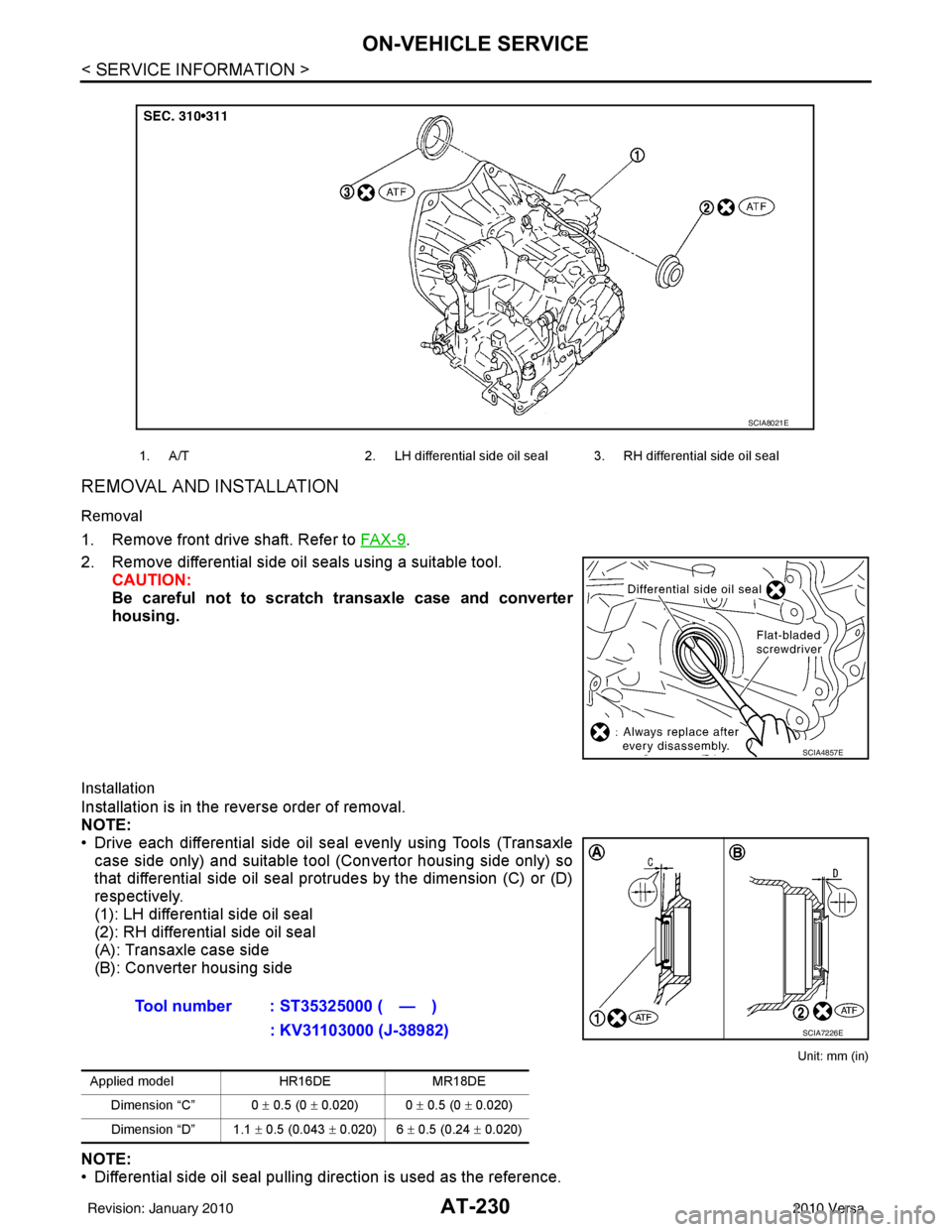
REMOVAL AND INSTALLATION
Removal
1. Remove front drive shaft. Refer to FA X - 9.
2. Remove differential side oil seals using a suitable tool. CAUTION:
Be careful not to scratch transaxle case and converter
housing.
Installation
Installation is in the reverse order of removal.
NOTE:
• Drive each differential side oil seal evenly using Tools (Transaxlecase side only) and suitable tool (Convertor housing side only) so
that differential side oil seal prot rudes by the dimension (C) or (D)
respectively.
(1): LH differential side oil seal
(2): RH differential side oil seal
(A): Transaxle case side
(B): Converter housing side
Unit: mm (in)
NOTE:
• Differential side oil seal pulling direction is used as the reference.
1. A/T 2. LH differential side oil seal 3. RH differential side oil seal
SCIA8021E
SCIA4857E
Tool number : ST35325000 ( — )
: KV31103000 (J-38982)
Applied model HR16DEMR18DE
Dimension “C” 0 ± 0.5 (0 ± 0.020) 0 ± 0.5 (0 ± 0.020)
Dimension “D” 1.1 ± 0.5 (0.043 ± 0.020) 6 ± 0.5 (0.24 ± 0.020)
SCIA7226E
Revision: January 20102010 Versa
Page 332 of 3745

REPAIR FOR COMPONENT PARTSAT-315
< SERVICE INFORMATION >
DE
F
G H
I
J
K L
M A
B
AT
N
O P
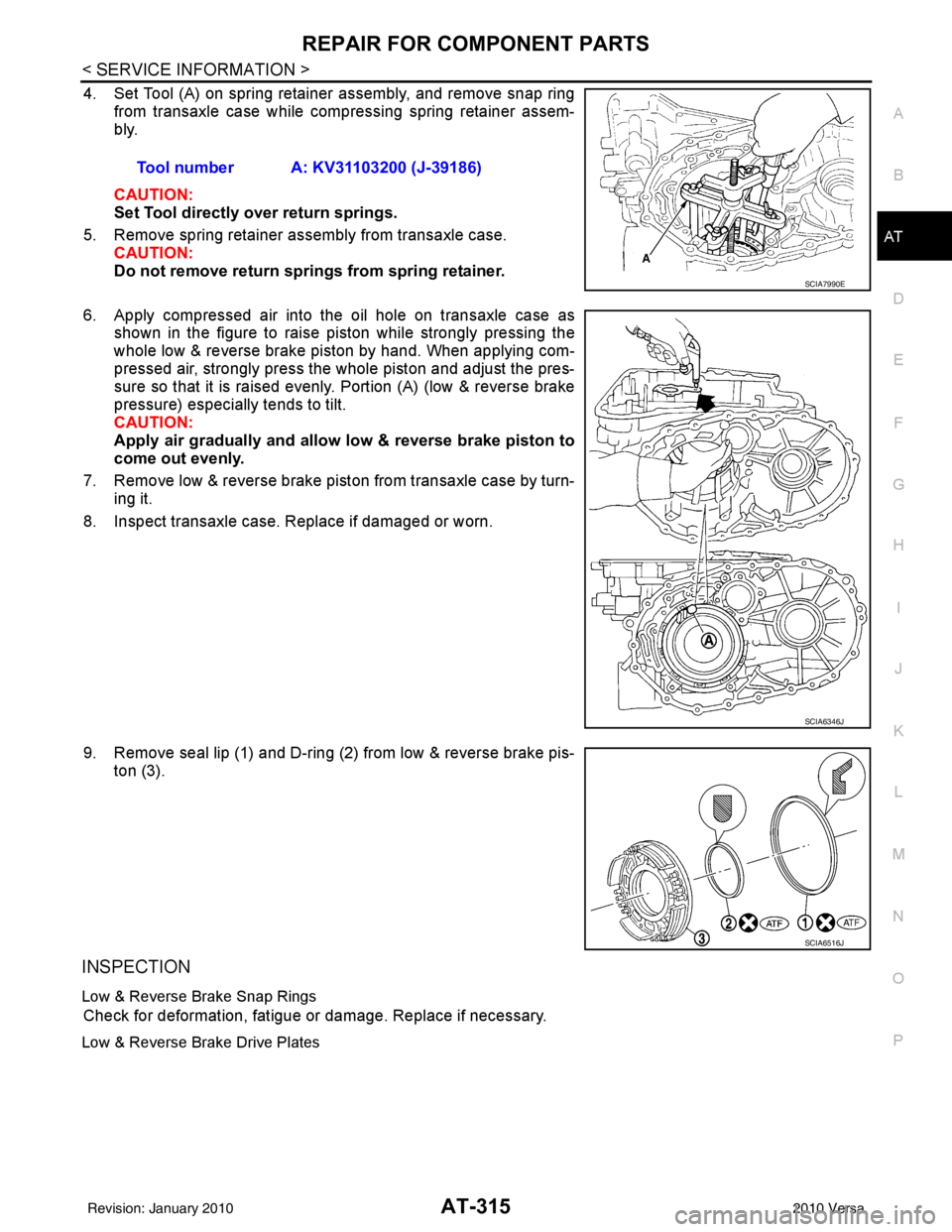
4. Set Tool (A) on spring retainer assembly, and remove snap ring from transaxle case while compressing spring retainer assem-
bly.
CAUTION:
Set Tool directly over return springs.
5. Remove spring retainer assembly from transaxle case. CAUTION:
Do not remove return springs from spring retainer.
6. Apply compressed air into the oil hole on transaxle case as shown in the figure to raise piston while strongly pressing the
whole low & reverse brake piston by hand. When applying com-
pressed air, strongly press the whole piston and adjust the pres-
sure so that it is raised evenly. Portion (A) (low & reverse brake
pressure) especially tends to tilt.
CAUTION:
Apply air gradually and allow low & reverse brake piston to
come out evenly.
7. Remove low & reverse brake piston from transaxle case by turn- ing it.
8. Inspect transaxle case. Replace if damaged or worn.
9. Remove seal lip (1) and D-ring (2) from low & reverse brake pis- ton (3).
INSPECTION
Low & Reverse Brake Snap Rings
Check for deformation, fatigue or damage. Replace if necessary.
Low & Reverse Brake Drive Plates
Tool number A: KV31103200 (J-39186)
SCIA7990E
SCIA6346J
SCIA6516J
Revision: January 20102010 Versa