2010 NISSAN LATIO ESP
[x] Cancel search: ESPPage 598 of 3745

INTELLIGENT KEY SYSTEMBL-89
< SERVICE INFORMATION >
C
DE
F
G H
J
K L
M A
B
BL
N
O P
Operation Description
• When the Intelligent Key unit detects that each request sw
itch is pressed, it starts the outside key antenna
and inside key antenna corresponding to the pressed request switch and sends the request signal to the
Intelligent Key. And then, make sure that the Intelligent Key is near door.
• If the Intelligent Key is within the outside key antenna detection area, it receives the request signal and sends the key ID signal to the Intelligent Key unit.
• Intelligent Key unit receives the key ID signal and compares it with the registered key ID.
• If the key ID check result is OK, the Intelligent Ke y unit sends the door lock/unlock request signal to BCM
(Body control module) via CAN communication line.
• Intelligent Key unit sends the door lock/unlock signal and sounds Intelligent Key warning buzzer (lock: 2 times, unlock: 1 time) at the same time.
• When BCM receives the door lock/unlock signal, it oper ates door lock actuator and flashes the hazard warn-
ing lamp (lock: 2 times, unlock: 1 time) at the same time as reminder.
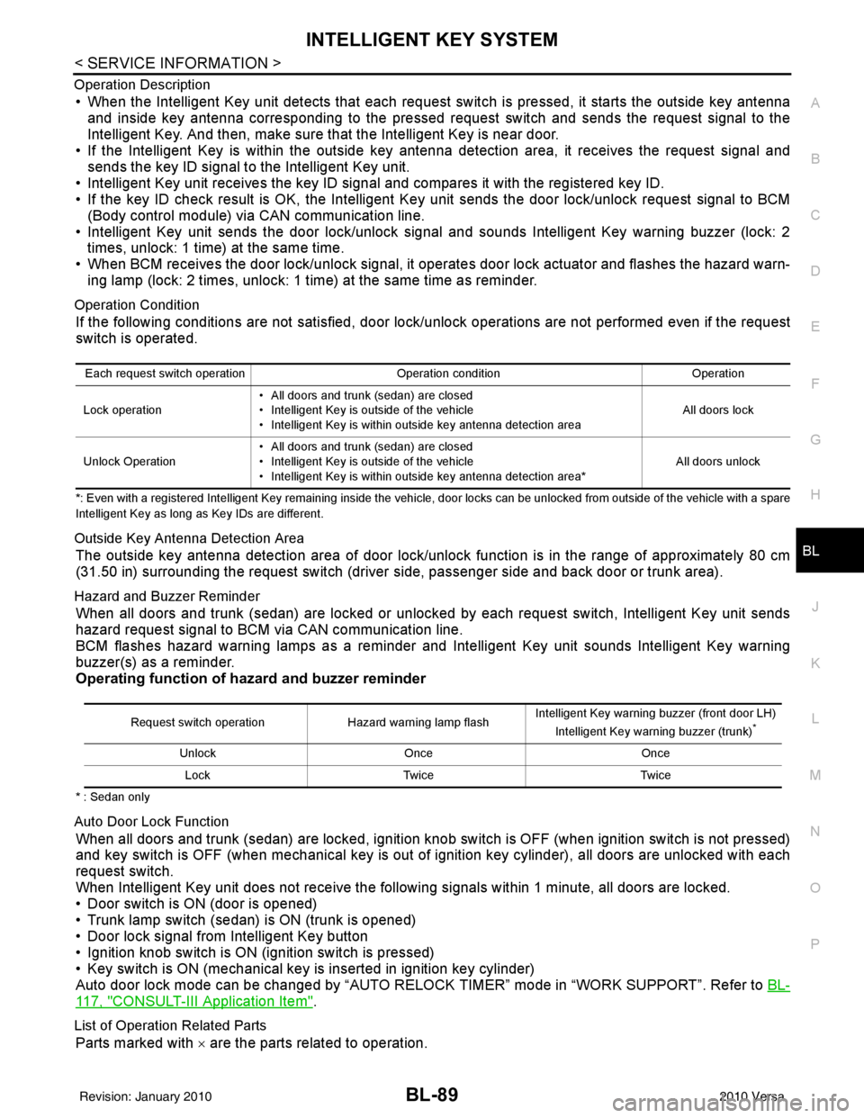
Operation Condition
If the following conditions are not satisfied, door lock/unlock operations are not performed even if the request
switch is operated.
*: Even with a registered Intelligent Key remaining inside the vehicle, door locks can be unlocked from outside of the vehicle with a spare
Intelligent Key as long as Key IDs are different.
Outside Key Antenna Detection Area
The outside key antenna detection area of door lock/unloc k function is in the range of approximately 80 cm
(31.50 in) surrounding the request switch (driver side, passenger side and back door or trunk area).
Hazard and Buzzer Reminder
When all doors and trunk (sedan) are locked or unlocked by each request switch, Intelligent Key\
unit sends
hazard request signal to BCM via CAN communication line.
BCM flashes hazard warning lamps as a reminder and Intelligent Key unit sounds Intelligent Key warning
buzzer(s) as a reminder.
Operating function of hazard and buzzer reminder
* : Sedan only
Auto Door Lock Function
When all doors and trunk (sedan) are locked, ignition knob sw itch is OFF (when ignition switch is not pressed)
and key switch is OFF (when mechanical key is out of ignition key cylinder), all doors are unlocked with each
request switch.
When Intelligent Key unit does not receive the following signals within 1 minute, all doors are locked.
• Door switch is ON (door is opened)
• Trunk lamp switch (sedan) is ON (trunk is opened)
• Door lock signal from Intelligent Key button
• Ignition knob switch is ON (ignition switch is pressed)
• Key switch is ON (mechanical key is inserted in ignition key cylinder)
Auto door lock mode can be changed by “AUTO RELOCK TIMER” mode in “WORK SUPPORT”. Refer to BL-
117, "CONSULT-III Application Item".
List of Operation Related Parts
Parts marked with × are the parts related to operation.
Each request switch operation Operation conditionOperation
Lock operation • All doors and trunk (sedan) are closed
• Intelligent Key is outside of the vehicle
• Intelligent Key is within outside key antenna detection area All doors lock
Unlock Operation • All doors and trunk (sedan) are closed
• Intelligent Key is outside of the vehicle
• Intelligent Key is within outside key antenna detection area*
All doors unlock
Request switch operation
Hazard warning lamp flashIntelligent Key warning buzzer (front door LH)
Intelligent Key warning buzzer (trunk)*
Unlock Once Once
Lock Twice Twice
Revision: January 20102010 Versa
Page 625 of 3745

BL-116
< SERVICE INFORMATION >
INTELLIGENT KEY SYSTEM
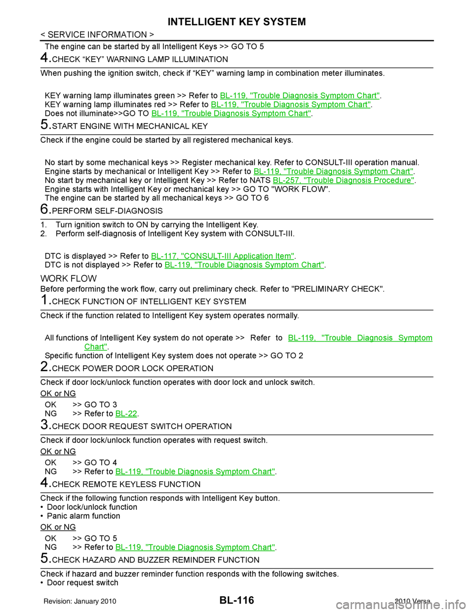
The engine can be started by all Intelligent Keys >> GO TO 5
4.CHECK “KEY” WARNING LAMP ILLUMINATION
When pushing the ignition switch, check if “KEY” warning lamp in combination meter illuminates.
KEY warning lamp illuminates green >> Refer to BL-119, "
Trouble Diagnosis Symptom Chart".
KEY warning lamp illuminates red >> Refer to BL-119, "
Trouble Diagnosis Symptom Chart".
Does not illuminate>>GO TO BL-119, "
Trouble Diagnosis Symptom Chart".
5.START ENGINE WITH MECHANICAL KEY
Check if the engine could be started by all registered mechanical keys.
No start by some mechanical keys >> Register mechanical key. Refer to CONSULT-III operation manual.
Engine starts by mechanical or Intelligent Key >> Refer to BL-119, "
Trouble Diagnosis Symptom Chart".
No start by mechanical key or Intelligent Key >> Refer to NATS BL-257, "
Trouble Diagnosis Procedure".
Engine starts with Intelligent Key or mechanical key >> GO TO "WORK FLOW".
The engine can be started by all mechanical keys >> GO TO 6
6.PERFORM SELF-DIAGNOSIS
1. Turn ignition switch to ON by carrying the Intelligent Key.
2. Perform self-diagnosis of Intel ligent Key system with CONSULT-III.
DTC is displayed >> Refer to BL-117, "
CONSULT-III Application Item".
DTC is not displayed >> Refer to BL-119, "
Trouble Diagnosis Symptom Chart".
WORK FLOW
Before performing the work flow, carry out prel iminary check. Refer to "PRELIMINARY CHECK".
1.CHECK FUNCTION OF INTELLIGENT KEY SYSTEM
Check if the function related to Intelligent Key system operates normally.
All functions of Intelligent Key system do not operate >> Refer to BL-119, "
Trouble Diagnosis Symptom
Chart".
Specific function of Intelligent Ke y system does not operate >> GO TO 2
2.CHECK POWER DOOR LOCK OPERATION
Check if door lock/unlock function operates with door lock and unlock switch.
OK or NG
OK >> GO TO 3
NG >> Refer to BL-22
.
3.CHECK DOOR REQUEST SWITCH OPERATION
Check if door lock/unlock function operates with request switch.
OK or NG
OK >> GO TO 4
NG >> Refer to BL-119, "
Trouble Diagnosis Symptom Chart".
4.CHECK REMOTE K EYLESS FUNCTION
Check if the following function responds with Intelligent Key button.
• Door lock/unlock function
• Panic alarm function
OK or NG
OK >> GO TO 5
NG >> Refer to BL-119, "
Trouble Diagnosis Symptom Chart".
5.CHECK HAZARD AND BUZZ ER REMINDER FUNCTION
Check if hazard and buzzer reminder function responds with the following switches.
• Door request switch
Revision: January 20102010 Versa
Page 652 of 3745

INTELLIGENT KEY SYSTEMBL-143
< SERVICE INFORMATION >
C
DE
F
G H
J
K L
M A
B
BL
N
O P
OK or NG
OK >> Intelligent Key warning buzzer is OK.
NG >> Replace inoperative Intelligent Key warning buzzer.
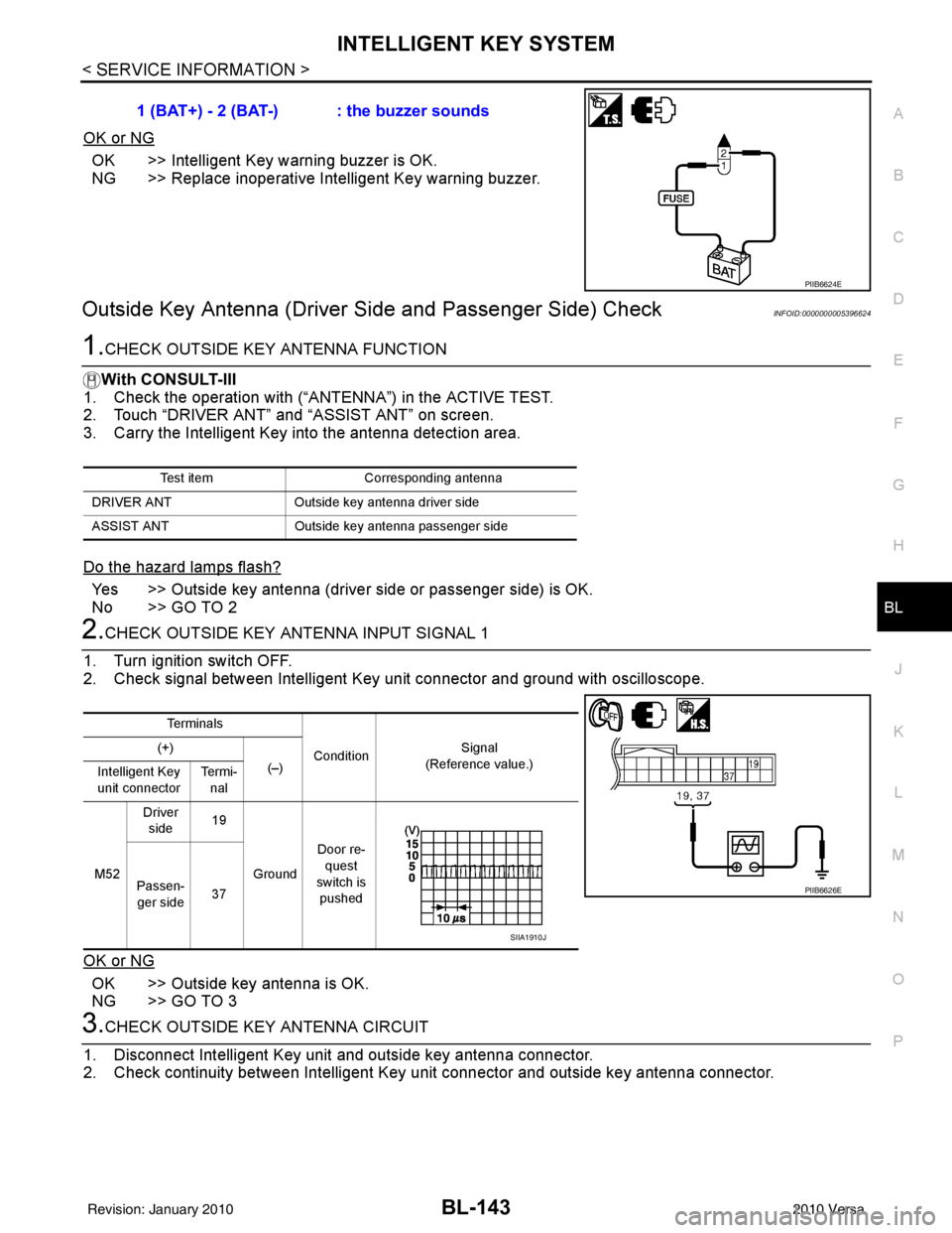
Outside Key Antenna (Driver Si de and Passenger Side) CheckINFOID:0000000005396624
1.CHECK OUTSIDE KEY ANTENNA FUNCTION
With CONSULT-III
1. Check the operation with (“ANT ENNA”) in the ACTIVE TEST.
2. Touch “DRIVER ANT” and “ASSIST ANT” on screen.
3. Carry the Intelligent Key into the antenna detection area.
Do the hazard lamps flash?
Yes >> Outside key antenna (driver side or passenger side) is OK.
No >> GO TO 2
2.CHECK OUTSIDE KEY ANTENNA INPUT SIGNAL 1
1. Turn ignition switch OFF.
2. Check signal between Intelligent Key unit connector and ground with oscilloscope.
OK or NG
OK >> Outside key antenna is OK.
NG >> GO TO 3
3.CHECK OUTSIDE KEY ANTENNA CIRCUIT
1. Disconnect Intelligent Key unit and outside key antenna connector.
2. Check continuity between Intelligent Key unit connector and outside key antenna connector. 1 (BAT+) - 2 (BAT-) : the buzzer sounds
PIIB6624E
Test item
Corresponding antenna
DRIVER ANT Outside key antenna driver side
ASSIST ANT Outside key antenna pass enger side
Te r m i n a l s
Condition Signal
(Reference value.)
(+)
(–)
Intelligent Key
unit connector Te r m i -
nal
M52 Driver
side 19
Ground Door re-
quest
switch is pushed
Passen-
ger side 37
PIIB6626E
SIIA1910J
Revision: January 20102010 Versa
Page 654 of 3745

INTELLIGENT KEY SYSTEMBL-145
< SERVICE INFORMATION >
C
DE
F
G H
J
K L
M A
B
BL
N
O P
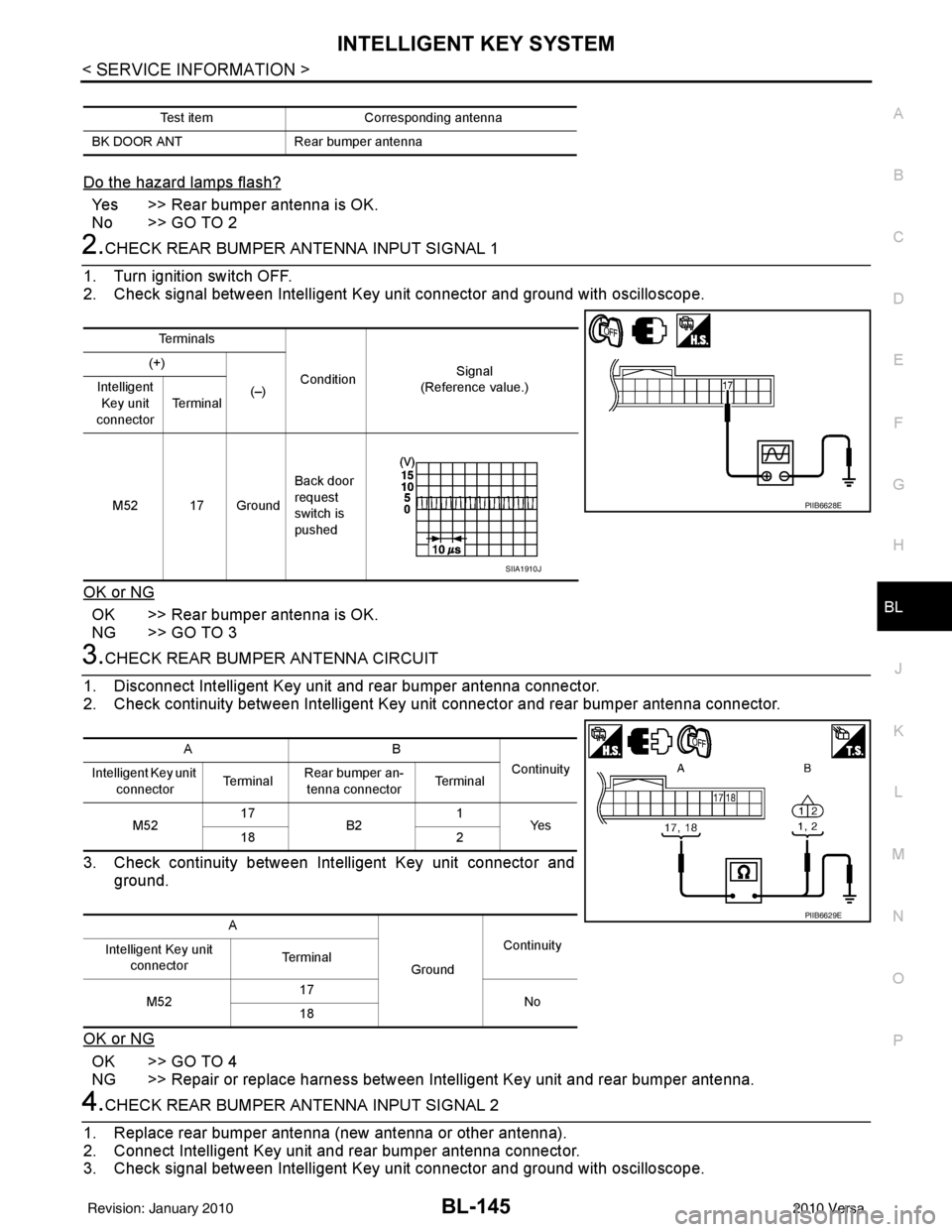
Do the hazard lamps flash?
Yes >> Rear bumper antenna is OK.
No >> GO TO 2
2.CHECK REAR BUMPER ANTENNA INPUT SIGNAL 1
1. Turn ignition switch OFF.
2. Check signal between Intelligent Key unit connector and ground with oscilloscope.
OK or NG
OK >> Rear bumper antenna is OK.
NG >> GO TO 3
3.CHECK REAR BUMPER ANTENNA CIRCUIT
1. Disconnect Intelligent Key unit and rear bumper antenna connector.
2. Check continuity between Intelligent Key unit connector and rear bumper antenna connector.
3. Check continuity between Intelligent Key unit connector and ground.
OK or NG
OK >> GO TO 4
NG >> Repair or replace harness between Intelligent Key unit and rear bumper antenna.
4.CHECK REAR BUMPER ANTENNA INPUT SIGNAL 2
1. Replace rear bumper antenna (new antenna or other antenna).
2. Connect Intelligent Key unit and rear bumper antenna connector.
3. Check signal between Intelligent Key unit connector and ground with oscilloscope.
Test item Corresponding antenna
BK DOOR ANT Rear bumper antenna
Te r m i n a l s
Condition Signal
(Reference value.)
(+)
(–)
Intelligent
Key unit
connector Te r m i n a l
M52 17 Ground Back door
request
switch is
pushed
PIIB6628E
SIIA1910J
AB
Continuity
Intelligent Key unit
connector Te r m i n a l
Rear bumper an-
tenna connector Te r m i n a l
M52 17
B2 1
Ye s
18 2
A GroundContinuity
Intelligent Key unit
connector Te r m i n a l
M52 17
No
18
PIIB6629E
Revision: January 20102010 Versa
Page 900 of 3745
![NISSAN LATIO 2010 Service Repair Manual BRC-10
< SERVICE INFORMATION >[ABS]
TROUBLE DIAGNOSIS
TROUBLE DIAGNOSIS
How to Perform Trouble Diagnosis
for Quick and Accurate RepairINFOID:0000000005397032
INTRODUCTION
The ABS system has an electr NISSAN LATIO 2010 Service Repair Manual BRC-10
< SERVICE INFORMATION >[ABS]
TROUBLE DIAGNOSIS
TROUBLE DIAGNOSIS
How to Perform Trouble Diagnosis
for Quick and Accurate RepairINFOID:0000000005397032
INTRODUCTION
The ABS system has an electr](/manual-img/5/57358/w960_57358-899.png)
BRC-10
< SERVICE INFORMATION >[ABS]
TROUBLE DIAGNOSIS
TROUBLE DIAGNOSIS
How to Perform Trouble Diagnosis
for Quick and Accurate RepairINFOID:0000000005397032
INTRODUCTION
The ABS system has an electronic control unit to control major func-
tions. The control unit accepts input signals from sensors and con-
trols actuator operation. It is also important to check for air leaks in
the booster or brake and vacuum lines, lack of brake fluid, or other
malfunctions in the brake system.
It is much more difficult to diagnose a malfunction that occurs inter-
mittently rather than continuously. Most intermittent conditions are
caused by poor electrical connections or damaged wiring. In this
case, careful checking of suspicious circuits may help prevent the
replacement of good parts.
A visual check only may not find t he cause of the malfunction, so a
road test should be performed.
Before undertaking actual checks, take just a few minutes to talk with
a customer who approaches with an ABS complaint. The customer
is a very good source of informati on, especially for intermittent condi-
tions. Through the talks with the customer, find out what symptoms
are present and under what conditions they occur.
Start your diagnosis by looking for “conventional” malfunctions first.
This is one of the best ways to troubleshoot brake malfunctions on
an ABS equipped vehicle. Also check related Service Bulletins for
information.
SEF233G
SEF234G
Revision: January 20102010 Versa
Page 937 of 3745
![NISSAN LATIO 2010 Service Repair Manual TROUBLE DIAGNOSISBRC-47
< SERVICE INFORMATION > [VDC/TCS/ABS]
C
D
E
G H
I
J
K L
M A
B
BRC
N
O P
TROUBLE DIAGNOSIS
How to Perform Trouble Diagnosis for Quick and Accurate RepairINFOID:0000000005612151
NISSAN LATIO 2010 Service Repair Manual TROUBLE DIAGNOSISBRC-47
< SERVICE INFORMATION > [VDC/TCS/ABS]
C
D
E
G H
I
J
K L
M A
B
BRC
N
O P
TROUBLE DIAGNOSIS
How to Perform Trouble Diagnosis for Quick and Accurate RepairINFOID:0000000005612151](/manual-img/5/57358/w960_57358-936.png)
TROUBLE DIAGNOSISBRC-47
< SERVICE INFORMATION > [VDC/TCS/ABS]
C
D
E
G H
I
J
K L
M A
B
BRC
N
O P
TROUBLE DIAGNOSIS
How to Perform Trouble Diagnosis for Quick and Accurate RepairINFOID:0000000005612151
INTRODUCTION
The ABS/TCS/VDC system has an el ectronic control unit to control
major functions. The control unit accepts input signals from sensors
and controls actuator operation. It is also important to check for con-
ventional malfunctions such as air leaks in the booster or lines, lack
of brake fluid, or other malfunctions with the brake system.
It is much more difficult to diagnose a malfunction that occurs inter-
mittently rather than continuously. Most intermittent malfunctions are
caused by poor electrical connections or wiring. In this case, careful
checking of suspicious circuits may help prevent the replacement of
good parts.
A visual check only may not find t he cause of the malfunction, so a
road test should be performed.
Before undertaking actual checks, take just a few minutes to talk with
a customer who approaches with an ABS/TCS/VDC complaint. The
customer is a very good source of information, especially for inter-
mittent malfunctions. Through the talks with the customer, find out
what symptoms are present and under what conditions they occur.
Start your diagnosis by looking fo r “conventional” malfunctions first.
This is one of the best ways to troubleshoot brake malfunctions on
an ABS/TCS/VDC equipped vehicle. Also check related Service Bul-
letins for information.
SEF233G
SEF234G
Revision: January 20102010 Versa
Page 947 of 3745
![NISSAN LATIO 2010 Service Repair Manual TROUBLE DIAGNOSISBRC-57
< SERVICE INFORMATION > [VDC/TCS/ABS]
C
D
E
G H
I
J
K L
M A
B
BRC
N
O P
• If there is damage to the connection flare nut or ABS actuator and electric unit (control unit) scr NISSAN LATIO 2010 Service Repair Manual TROUBLE DIAGNOSISBRC-57
< SERVICE INFORMATION > [VDC/TCS/ABS]
C
D
E
G H
I
J
K L
M A
B
BRC
N
O P
• If there is damage to the connection flare nut or ABS actuator and electric unit (control unit) scr](/manual-img/5/57358/w960_57358-946.png)
TROUBLE DIAGNOSISBRC-57
< SERVICE INFORMATION > [VDC/TCS/ABS]
C
D
E
G H
I
J
K L
M A
B
BRC
N
O P
• If there is damage to the connection flare nut or ABS actuator and electric unit (control unit) screw, replace the damaged part and recheck for leaks.
• When there is fluid leaking or seeping from a fluid connection, use a clean cloth to wipe off the fluid and
recheck for leaks. If fluid is still seeping out, replace the damaged part. If the fluid is leaking at the ABS
actuator and electric unit (control unit), replace the ABS actuator and electric unit (control unit) assem-
bly.
CAUTION:
The ABS actuator and electric unit (control unit) cannot be disassembl\
ed and must be replaced
as an assembly.
3. Check the brake pads for excessive wear.
POWER SYSTEM TERMINAL LOOSENESS AND BATTERY INSPECTION
Make sure the battery positive cable, negative cabl e and ground connection are not loose. In addition, make
sure the battery is sufficiently charged.
ABS WARNING LAMP, SLIP INDICATOR LAMP AND VDC OFF INDICATOR LAMP INSPECTION
1. Make sure ABS warning lamp, SLIP indicator lamp and VDC OFF indicator lamp (when VDC OFF switch
is off), turn on for approximately 2 seconds when the igni tion switch is turned ON. If they do not, check the
VDC OFF indicator lamp and then VDC OFF switch. Refer to BRC-79, "
Component Inspection". Check
CAN communications. If there are no errors with VDC OFF switch and CAN communication system,
check combination meter. Refer to DI-32, "
Component Inspection".
2. Make sure the lamps turn off approximately 2 seconds after the ignition switch is turned ON. If the lamp does not turn off, conduct self-diagnosis.
3. With the engine running, make sure VDC OFF indicator lamp turns on and off when VDC OFF switch is turned on and off. If the indicator lamp status does not correspond to switch operation, check the VDC
OFF switch system. Refer to BRC-79, "
Component Inspection".
4. Make sure ABS warning lamp, SLIP indicator lamp and VDC OFF indicator lamp turn off approximately 2 seconds after the engine is started. If ABS warning la mp, SLIP indicator lamp or VDC OFF indicator lamp
have not turned off 10 seconds after the engine has been started, conduct self-diagnosis of the ABS actu-
ator and electric unit (control unit).
5. After conducting the self-diagnosis, be sure to erase the error memory. Refer to BRC-60, "
CONSULT-III
Function (ABS)".
Warning Lamp and Indicator TimingINFOID:0000000005612156
×: ON –: OFF
Control Unit Input/Out put Signal StandardINFOID:0000000005612157
REFERENCE VALUE FROM CONSULT-III
CAUTION:
The display shows the control unit calculation data, so a normal value might be displayed even in the
event the output circuit (harness) is open or short circuited.
Condition ABS
warning lamp VDC OFF
indicator lamp SLIP
indicator lamp Remarks
When the ignition switch is OFF ––– –
After the ignition switch is turned
ON
For approx. 2 seconds ×××
–
Ignition switch ON
Approx. 2 seconds later ––– –
When the VDC OFF switch turns
ON (VDC function OFF). –
×––
ABS/TCS/VDC malfunction ×××
–
×× –When the ABS/TCS/VDC control
unit is malfunctioning (power sup-
ply or ground malfunction).
When the VDC is malfunctioning. –×× –
Revision: January 20102010 Versa
Page 1044 of 3745
![NISSAN LATIO 2010 Service Repair Manual PRECAUTIONSCVT-11
< SERVICE INFORMATION > [RE0F08B]
D
E
F
G H
I
J
K L
M A
B
CVT
N
O P
• When connecting or disconnecting pin connectors into or
from TCM, take care not to damage pin terminals (bend NISSAN LATIO 2010 Service Repair Manual PRECAUTIONSCVT-11
< SERVICE INFORMATION > [RE0F08B]
D
E
F
G H
I
J
K L
M A
B
CVT
N
O P
• When connecting or disconnecting pin connectors into or
from TCM, take care not to damage pin terminals (bend](/manual-img/5/57358/w960_57358-1043.png)
PRECAUTIONSCVT-11
< SERVICE INFORMATION > [RE0F08B]
D
E
F
G H
I
J
K L
M A
B
CVT
N
O P
• When connecting or disconnecting pin connectors into or
from TCM, take care not to damage pin terminals (bend or
break).
When connecting pin connectors make sure that there are not
any bends or breaks on TCM pin terminal.
• Before replacing TCM, perform TCM input/output signal
inspection and make sure whether TCM functions properly or
not. CVT-46, "
TCM Terminal and Reference Value".
• After performing each TROUBL E DIAGNOSIS, perform “DTC
Confirmation Procedure”.
If the repair is completed the DTC should not be displayed in
the “DTC Confirmation Procedure”.
• Always use the specified br and of CVT fluid. Refer to MA-14, "
Flu-
ids and Lubricants".
• Use lint-free paper, not cloth rags, during work.
• After replacing the CVT fluid, dispose of the waste oil using the methods prescribed by law, ordinance, etc.
Service Notice or PrecautionINFOID:0000000005397764
CVT FLUID COOLER SERVICE
If CVT fluid contains friction material (clutches, brakes , etc.), or if an CVT is replaced, inspect and clean the
CVT fluid cooler mounted in the radiator or replace the radiator. Flush cooler lines using cleaning solvent and
compressed air after repair. For CVT fluid cooler cleaning procedure, refer to CVT-15, "
CVT Fluid Cooler
Cleaning". For radiator replacement, refer to CO-40.
OBD-II SELF-DIAGNOSIS
• CVT self-diagnosis is performed by the TCM in combination with the ECM. The results can be read through
the blinking pattern of the malfunction indi cator lamp (MIL). Refer to the table on CVT-48, "
CONSULT-III
Function (TRANSMISSION)" for the indicator used to display each self-diagnostic result.
• The self-diagnostic results indicated by the MIL are automatically stored in both the ECM and TCM memo- ries.
Always perform the procedure on CVT-27, "
OBD-II Diagnostic Trouble Code (DTC)" to complete the
repair and avoid unnecessary blinking of the MIL.
For details of OBD-II, refer to EC-541, "
Introduction".
• Certain systems and components, especially those re lated to OBD, may use the new style slide-lock-
ing type harness connector. For description and how to disconnect, refer to PG-66
.
ATFTEMP COUNT Conversion Table INFOID:0000000005709762
SEF291H
MEF040DA
SEF217U
Revision: January 20102010 Versa