2010 NISSAN LATIO warning
[x] Cancel search: warningPage 753 of 3745
BL-244
< SERVICE INFORMATION >
VEHICLE SECURITY (THEFT WARNING) SYSTEM
OK >> GO TO 3
NG >> Repair or replace harness.
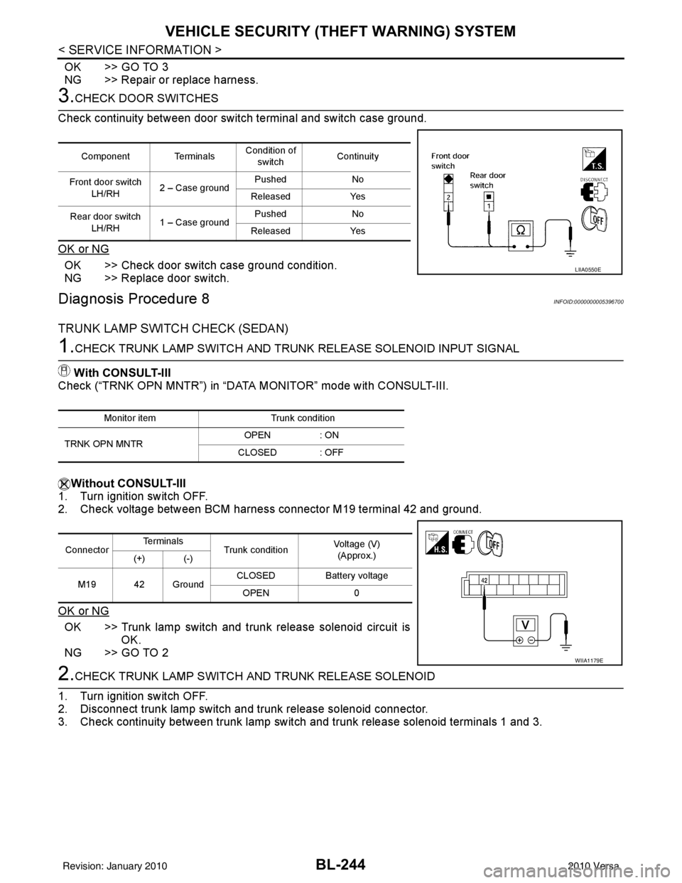
3.CHECK DOOR SWITCHES
Check continuity between door switch terminal and switch case ground.
OK or NG
OK >> Check door switch case ground condition.
NG >> Replace door switch.
Diagnosis Procedure 8INFOID:0000000005396700
TRUNK LAMP SWITCH CHECK (SEDAN)
1.CHECK TRUNK LAMP SWITCH AND TRUNK RELEASE SOLENOID INPUT SIGNAL
With CONSULT-III
Check (“TRNK OPN MNTR”) in “DATA MONITOR” mode with CONSULT-III.
Without CONSULT-III
1. Turn ignition switch OFF.
2. Check voltage between BCM harness connector M19 terminal 42 and ground.
OK or NG
OK >> Trunk lamp switch and trunk release solenoid circuit is
OK.
NG >> GO TO 2
2.CHECK TRUNK LAMP SWITCH A ND TRUNK RELEASE SOLENOID
1. Turn ignition switch OFF.
2. Disconnect trunk lamp switch and trunk release solenoid connector.
3. Check continuity between trunk lamp switch and trunk release solenoid terminals 1 and 3.
Component TerminalsCondition of
switch Continuity
Front door switch LH/RH 2 – Case ground Pushed
No
Released Yes
Rear door switch LH/RH 1 – Case ground Pushed
No
Released Yes
LIIA0550E
Monitor item Trunk condition
TRNK OPN MNTR OPEN
: ON
CLOSED : OFF
Connector Te r m i n a l s
Trunk condition Voltage (V)
(Approx.)
(+) (-)
M19 42 Ground CLOSED
Battery voltage
OPEN 0
WIIA1179E
Revision: January 20102010 Versa
Page 754 of 3745
VEHICLE SECURITY (THEFT WARNING) SYSTEMBL-245
< SERVICE INFORMATION >
C
DE
F
G H
J
K L
M A
B
BL
N
O P
OK or NG
OK >> GO TO 3
NG >> Replace trunk lamp switch and trunk release solenoid.
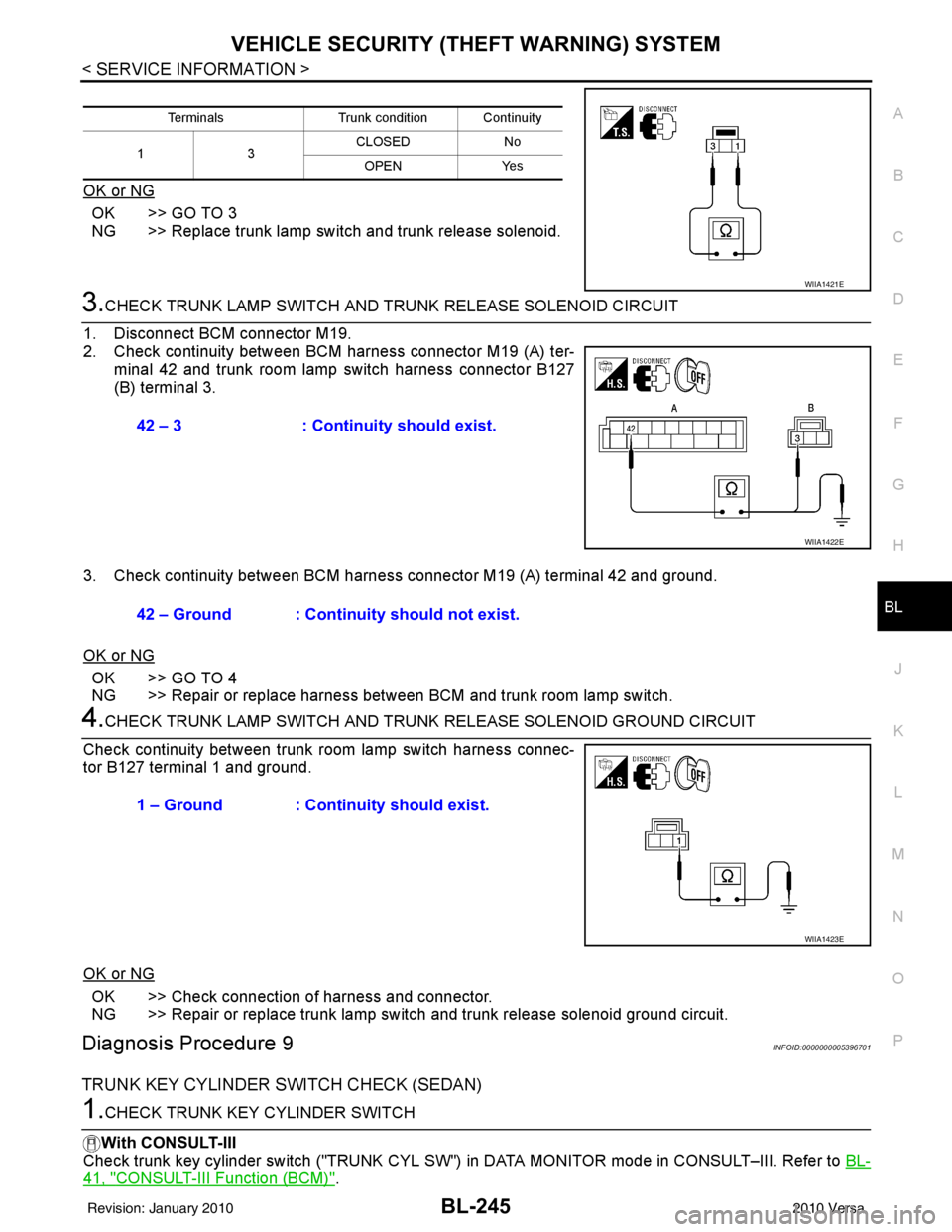
3.CHECK TRUNK LAMP SWITCH AND T RUNK RELEASE SOLENOID CIRCUIT
1. Disconnect BCM connector M19.
2. Check continuity between BCM harness connector M19 (A) ter- minal 42 and trunk room lamp switch harness connector B127
(B) terminal 3.
3. Check continuity between BCM harness connector M19 (A) terminal 42 and ground.
OK or NG
OK >> GO TO 4
NG >> Repair or replace harness between BCM and trunk room lamp switch.
4.CHECK TRUNK LAMP SWITCH AND TRUNK RELEASE SOLENOID GROUND CIRCUIT
Check continuity between trunk room lamp switch harness connec-
tor B127 terminal 1 and ground.
OK or NG
OK >> Check connection of harness and connector.
NG >> Repair or replace trunk lamp switch and trunk release solenoid ground circuit.
Diagnosis Procedure 9INFOID:0000000005396701
TRUNK KEY CYLINDER SWITCH CHECK (SEDAN)
1.CHECK TRUNK KEY CYLINDER SWITCH
With CONSULT-III
Check trunk key cylinder switch ("TRUNK CYL SW") in DATA MONITOR mode in CONSULT–III. Refer to BL-
41, "CONSULT-III Function (BCM)".
TerminalsTrunk condition Continuity
13 CLOSED
No
OPEN Yes
WIIA1421E
42 – 3: Continuity should exist.
WIIA1422E
42 – Ground : Continuity should not exist.
1 – Ground : Continuity should exist.
WIIA1423E
Revision: January 20102010 Versa
Page 755 of 3745
BL-246
< SERVICE INFORMATION >
VEHICLE SECURITY (THEFT WARNING) SYSTEM
• When key inserted in trunk key cylinder is turned to FULL STROKE:
• When key is removed from the trunk key cylinder:
Without CONSULT-III
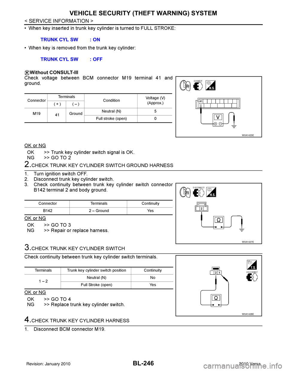
Check voltage between BCM connector M19 terminal 41 and
ground.
OK or NG
OK >> Trunk key cylinder switch signal is OK.
NG >> GO TO 2
2.CHECK TRUNK KEY CYLINDE R SWITCH GROUND HARNESS
1. Turn ignition switch OFF.
2. Disconnect trunk key cylinder switch.
3. Check continuity between trunk key cylinder switch connector B142 terminal 2 and body ground.
OK or NG
OK >> GO TO 3
NG >> Repair or replace harness.
3.CHECK TRUNK KEY CYLINDER SWITCH
Check continuity between trunk key cylinder switch terminals.
OK or NG
OK >> GO TO 4
NG >> Replace trunk key cylinder switch.
4.CHECK TRUNK KEY CYLINDER HARNESS
1. Disconnect BCM connector M19. TRUNK CYL SW : ON
TRUNK CYL SW : OFF
Connector
Te r m i n a l s
ConditionVoltage (V)
(Approx.)
( + ) ( – )
M19 41Ground Neutral (N)
5
Full stroke (open) 0
WIIA1425E
ConnectorTerminalsContinuity
B142 2 – Ground Yes
WIIA1427E
Terminals Trunk key cylinder switch position Continuity
1 – 2 Neutral (N)
No
Full Stroke (open) Yes
WIIA1428E
Revision: January 20102010 Versa
Page 756 of 3745
VEHICLE SECURITY (THEFT WARNING) SYSTEMBL-247
< SERVICE INFORMATION >
C
DE
F
G H
J
K L
M A
B
BL
N
O P
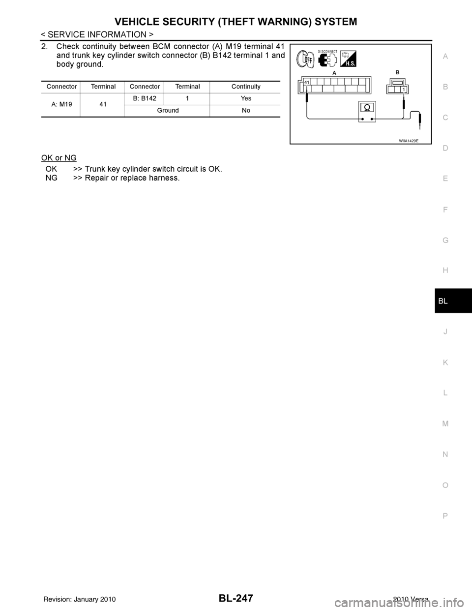
2. Check continuity between BCM connector (A) M19 terminal 41 and trunk key cylinder switch connector (B) B142 terminal 1 and
body ground.
OK or NG
OK >> Trunk key cylinder switch circuit is OK.
NG >> Repair or replace harness.
Connector Terminal Connector Terminal Continuity A: M19 41 B: B142 1
Yes
Ground No
WIIA1429E
Revision: January 20102010 Versa
Page 762 of 3745
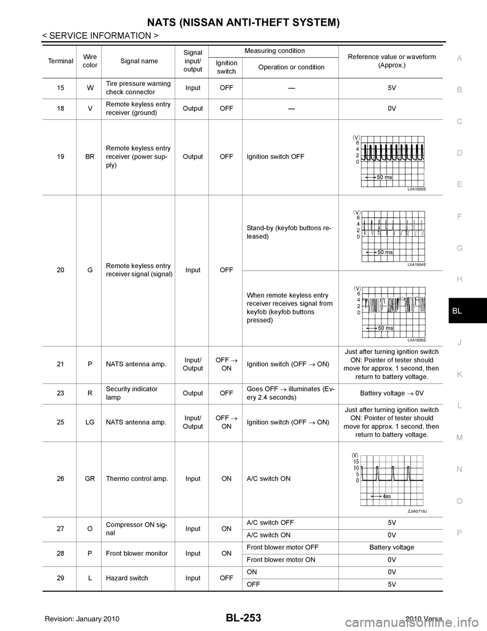
NATS (NISSAN ANTI-THEFT SYSTEM)BL-253
< SERVICE INFORMATION >
C
DE
F
G H
J
K L
M A
B
BL
N
O P
15 W Tire pressure warning
check connector
Input OFF
—5V
18 V Remote keyless entry
receiver (ground) Output OFF
—0V
19 BR Remote keyless entry
receiver (power sup-
ply) Output OFF Ignition switch OFF
20 G Remote keyless entry
receiver signal (signal)
Input OFFStand-by (keyfob buttons re-
leased)
When remote keyless entry
receiver receives signal from
keyfob (keyfob buttons
pressed)
21 P NATS antenna amp. Input/
Output OFF
→
ON Ignition switch (OFF → ON) Just after turning ignition switch
ON: Pointer of tester should
move for approx. 1 second, then
return to battery voltage.
23 R Security indicator
lamp Output OFF
Goes OFF
→ illuminates (Ev-
ery 2.4 seconds) Battery voltage
→ 0V
25 LG NATS antenna amp. Input/
Output OFF
→
ON Ignition switch (OFF → ON) Just after turning ignition switch
ON: Pointer of tester should
move for approx. 1 second, then return to battery voltage.
26 GR Thermo control amp. Input ON A/C switch ON
27 O Compressor ON sig-
nal Input ONA/C switch OFF
5V
A/C switch ON 0V
28 P Front blower monitor Input ON Front blower motor OFF
Battery voltage
Front blower motor ON 0V
29 L Hazard switch Input OFFON
0V
OFF 5V
Te r m i n a l
Wire
color Signal name Signal
input/
output Measuring condition
Reference value or waveform
(Approx.)
Ignition
switch Operation or condition
LIIA1893E
LIIA1894E
LIIA1895E
ZJIA0719J
Revision: January 20102010 Versa
Page 766 of 3745
NATS (NISSAN ANTI-THEFT SYSTEM)BL-257
< SERVICE INFORMATION >
C
DE
F
G H
J
K L
M A
B
BL
N
O P
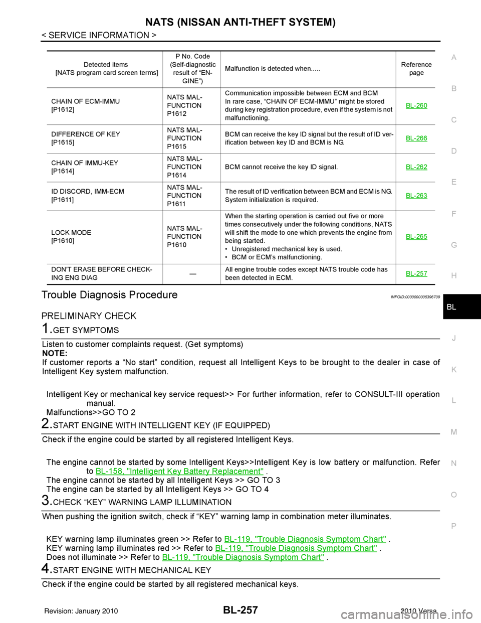
Trouble Diagnosis ProcedureINFOID:0000000005396709
PRELIMINARY CHECK
1.GET SYMPTOMS
Listen to customer complain ts request. (Get symptoms)
NOTE:
If customer reports a “No start” condition, request all Intelligent Keys to be brought to the dealer in case of
Intelligent Key system malfunction.
Intelligent Key or mechanical key service request>> Fo r further information, refer to CONSULT-III operation
manual.
Malfunctions>>GO TO 2
2.START ENGINE WITH INTELLIGENT KEY (IF EQUIPPED)
Check if the engine could be started by all registered Intelligent Keys.
The engine cannot be started by some Intelligent Keys>>Int elligent Key is low battery or malfunction. Refer
to BL-158, "
Intelligent Key Battery Replacement" .
The engine cannot be started by all Intelligent Keys >> GO TO 3
The engine can be started by all Intelligent Keys >> GO TO 4
3.CHECK “KEY” WARNING LAMP ILLUMINATION
When pushing the ignition switch, check if “KEY” warning lamp in combination meter illuminates.
KEY warning lamp illuminates green >> Refer to BL-119, "
Trouble Diagnosis Symptom Chart" .
KEY warning lamp illuminates red >> Refer to BL-119, "
Trouble Diagnosis Symptom Chart" .
Does not illuminate >> Refer to BL-119, "
Trouble Diagnosis Symptom Chart" .
4.START ENGINE WITH MECHANICAL KEY
Check if the engine could be started by all registered mechanical keys.
Detected items
[NATS program card screen terms] P No. Code
(Self-diagnostic result of “EN-
GINE”) Malfunction is detected when.....
Reference
page
CHAIN OF ECM-IMMU
[P1612] NATS MAL-
FUNCTION
P1612Communication impossible between ECM and BCM
In rare case, “CHAIN OF ECM-IMMU” might be stored
during key registration procedure, even if the system is not
malfunctioning.
BL-260
DIFFERENCE OF KEY
[P1615]NATS MAL-
FUNCTION
P1615BCM can receive the key ID signal but the result of ID ver-
ification between key ID and BCM is NG.
BL-266
CHAIN OF IMMU-KEY
[P1614]NATS MAL-
FUNCTION
P1614
BCM cannot receive the key ID signal.
BL-262
ID DISCORD, IMM-ECM
[P1611]NATS MAL-
FUNCTION
P1611The result of ID verification between BCM and ECM is NG.
System initialization is required.
BL-263
LOCK MODE
[P1610]NATS MAL-
FUNCTION
P1610When the starting operation is carried out five or more
times consecutively under the following conditions, NATS
will shift the mode to one which prevents the engine from
being started.
• Unregistered mechanical key is used.
• BCM or ECM’s malfunctioning.
BL-265
DON'T ERASE BEFORE CHECK-
ING ENG DIAG
—All engine trouble codes except NATS trouble code has
been detected in ECM.
BL-257
Revision: January 20102010 Versa
Page 823 of 3745

BL-314
< SERVICE INFORMATION >
BODY REPAIR
This section is prepared for technicians who have attained a high level of skill and experience in repairing col-
lision-damaged vehicles and also use modern service tools and equipment. Persons unfamiliar with body
repair techniques should not attempt to repair collision-damaged vehicles by using this section.
Technicians are also encouraged to read Body Repair M anual (Fundamentals) in order to ensure that the orig-
inal functions and quality of the vehicle can be mainta ined. The Body Repair Manual (Fundamentals) contains
additional information, including cautions and warnings, that are not including in this manual. Technicians
should refer to both manuals to ensure proper repairs.
Please note that this information is prepared for worldwide usage, and as such, certain procedures may not
apply in some regions or countries.
Revision: January 20102010 Versa
Page 850 of 3745

BR-2
< SERVICE INFORMATION >
PRECAUTIONS
SERVICE INFORMATION
PRECAUTIONS
Precaution for Supplemental Restraint System (SRS) "AIR BAG" and "SEAT BELT
PRE-TENSIONER"
INFOID:0000000005396972
The Supplemental Restraint System such as “A IR BAG” and “SEAT BELT PRE-TENSIONER”, used along
with a front seat belt, helps to reduce the risk or severity of injury to the driver and front passenger for certain
types of collision. This system includes seat belt switch inputs and dual stage front air bag modules. The SRS
system uses the seat belt switches to determine the front air bag deployment, and may only deploy one front
air bag, depending on the severity of a collision and w hether the front occupants are belted or unbelted.
Information necessary to service the system safely is included in the SRS and SB section of this Service Man-
ual.
WARNING:
• To avoid rendering the SRS inopera tive, which could increase the risk of personal injury or death in
the event of a collision which would result in air bag inflation, all maintenance must be performed by
an authorized NISSAN/INFINITI dealer.
• Improper maintenance, including incorrect removal and installation of the SRS can lead to personal
injury caused by unintent ional activation of the system. For re moval of Spiral Cable and Air Bag
Module, see the SRS section.
• Do not use electrical test equipmen t on any circuit related to the SRS unless instructed to in this
Service Manual. SRS wiring harn esses can be identified by yellow and/or orange harnesses or har-
ness connectors.
PRECAUTIONS WHEN USING POWER TOOLS (AIR OR ELECTRIC) AND HAMMERS
WARNING:
• When working near the Airbag Diagnosis Sensor Unit or other Airbag System sensors with the Igni-
tion ON or engine running, DO NOT use air or electri c power tools or strike near the sensor(s) with a
hammer. Heavy vibration could activate the sensor( s) and deploy the air bag(s), possibly causing
serious injury.
• When using air or electric power tools or hammers , always switch the Ignition OFF, disconnect the
battery, and wait at least 3 minu tes before performing any service.
Precaution Necessary for Steering W heel Rotation After Battery Disconnect
INFOID:0000000005396973
NOTE:
• This Procedure is applied only to models with Intelligent Key system and NATS (NISSAN ANTI-THEFT SYS-
TEM).
• Remove and install all control units after disconnecting both battery cables with the ignition knob in the
″LOCK ″ position.
• Always use CONSULT-III to perform self-diagnosis as a part of each function inspection after finishing work.
If DTC is detected, perform trouble diagnosis according to self-diagnostic results.
For models equipped with the Intelligent Key system and NATS, an electrically controlled steering lock mech-
anism is adopted on the key cylinder.
For this reason, if the battery is disconnected or if the battery is discharged, the steering wheel will lock and
steering wheel rotation will become impossible.
If steering wheel rotation is required when battery pow er is interrupted, follow the procedure below before
starting the repair operation.
OPERATION PROCEDURE
1. Connect both battery cables. NOTE:
Supply power using jumper cables if battery is discharged.
2. Use the Intelligent Key or mechanical key to turn the ignition switch to the ″ACC ″ position. At this time, the
steering lock will be released.
3. Disconnect both battery cables. The steering lock will remain released and the steering wheel can be rotated.
4. Perform the necessary repair operation.
Revision: January 20102010 Versa