2010 NISSAN LATIO flat tire
[x] Cancel search: flat tirePage 916 of 3745
![NISSAN LATIO 2010 Service Repair Manual BRC-26
< SERVICE INFORMATION >[ABS]
TROUBLE DIAGNOSIS FOR
SELF-DIAGNOSTIC ITEMS
TROUBLE DIAGNOSIS FOR SELF-DIAGNOSTIC ITEMS
Wheel Sensor SystemINFOID:0000000005397040
INSPECTION PROCEDURE
1.CONNECTOR NISSAN LATIO 2010 Service Repair Manual BRC-26
< SERVICE INFORMATION >[ABS]
TROUBLE DIAGNOSIS FOR
SELF-DIAGNOSTIC ITEMS
TROUBLE DIAGNOSIS FOR SELF-DIAGNOSTIC ITEMS
Wheel Sensor SystemINFOID:0000000005397040
INSPECTION PROCEDURE
1.CONNECTOR](/manual-img/5/57358/w960_57358-915.png)
BRC-26
< SERVICE INFORMATION >[ABS]
TROUBLE DIAGNOSIS FOR
SELF-DIAGNOSTIC ITEMS
TROUBLE DIAGNOSIS FOR SELF-DIAGNOSTIC ITEMS
Wheel Sensor SystemINFOID:0000000005397040
INSPECTION PROCEDURE
1.CONNECTOR INSPECTION
Disconnect the ABS actuator and electric unit (control unit) connector E33 and wheel sensor of malfunctioning
code.
Check the terminals for deformation, disconnection, looseness or damage.
OK or NG
OK >> GO TO 2.
NG >> Repair or replace as necessary.
2.CHECK WHEEL SENSOR OUTPUT SIGNAL
1. Connect ABS active wheel sensor tester (J-45741) to wheel sensor using appropriate adapter.
2. Turn on the ABS active wheel sensor tester power switch. NOTE:
The green POWER indicator should illuminate. If the POWER indicator does not illuminate, replace the
battery in the ABS active wheel sensor tester before proceeding.
3. Spin the wheel of the vehicle by hand and observe the red SENSOR indicator on the ABS active wheel
sensor tester. The red SENSOR indicator should flash on and off to indicate an output signal.
NOTE:
If the red SENSOR indicator illuminates but does not flash, reverse the polarity of the tester leads and
retest.
Does the ABS active wheel sensor tester detect a signal?
YES >> GO TO 3.
NO >> Replace the wheel sensor. Refer to BRC-34, "
Removal and Installation".
3.CHECK TIRES
Check for inflation pressure, wear and size of each tire. Refer to WT-28
.
Are tire pressure and size correct and is tire wear within specifications?
YES >> GO TO 4.
NO >> Adjust tire pressure or replace tire(s).
4.CHECK WHEEL BEARINGS
Check wheel bearing axial end play. Refer to FAX-6, "
On-Vehicle Inspection and Service" or RAX-6, "On-Vehi-
cle Inspection and Service".
OK or NG
OK >> GO TO 5.
NG >> Repair or replace as necessary. Refer to FA X - 6 , "
Removal and Installation" or RAX-6, "Removal
and Installation".
5.CHECK WIRING HARNESS FOR SHORT CIRCUIT
1. Turn ignition switch OFF.
2. Disconnect ABS actuator and elec tric unit (control unit) connec-
tor and wheel sensor connector of malfunction code No.
3. Check continuity between wheel sensor harness connector ter- minals and ground.
OK or NG
OK >> GO TO 6.
NG >> Repair the circuit.
6.CHECK WIRING HARNESS FOR OPEN CIRCUIT Continuity should not exist.
WFIA0498E
Revision: January 20102010 Versa
Page 957 of 3745
![NISSAN LATIO 2010 Service Repair Manual TROUBLE DIAGNOSIS FOR SELF-DIAGNOSTIC ITEMS
BRC-67
< SERVICE INFORMATION > [VDC/TCS/ABS]
C
D
E
G H
I
J
K L
M A
B
BRC
N
O P
TROUBLE DIAGNOSIS FOR SELF-DIAGNOSTIC ITEMS
Wheel Sensor System InspectionIN NISSAN LATIO 2010 Service Repair Manual TROUBLE DIAGNOSIS FOR SELF-DIAGNOSTIC ITEMS
BRC-67
< SERVICE INFORMATION > [VDC/TCS/ABS]
C
D
E
G H
I
J
K L
M A
B
BRC
N
O P
TROUBLE DIAGNOSIS FOR SELF-DIAGNOSTIC ITEMS
Wheel Sensor System InspectionIN](/manual-img/5/57358/w960_57358-956.png)
TROUBLE DIAGNOSIS FOR SELF-DIAGNOSTIC ITEMS
BRC-67
< SERVICE INFORMATION > [VDC/TCS/ABS]
C
D
E
G H
I
J
K L
M A
B
BRC
N
O P
TROUBLE DIAGNOSIS FOR SELF-DIAGNOSTIC ITEMS
Wheel Sensor System InspectionINFOID:0000000005612159
INSPECTION PROCEDURE
1.CONNECTOR INSPECTION
Disconnect the ABS actuator and electric unit (control unit) connector E33 and wheel sensor of malfunctioning
code.
Check the terminals for deformation, disconnection, looseness or damage.
OK or NG
OK >> GO TO 2.
NG >> Repair or replace as necessary.
2.CHECK WHEEL SENSOR OUTPUT SIGNAL
1. Connect ABS active wheel sensor tester (J- 45741) to wheel sensor using appropriate adapter.
2. Turn on the ABS active wheel sensor tester power switch.
NOTE:
The green POWER indicator should illuminate. If the POWER indicator does not illuminate, replace the
battery in the ABS active wheel sensor tester before proceeding.
3. Spin the wheel of the vehicle by hand and observe the red SENSOR indicator on the ABS active wheel
sensor tester. The red SENSOR indicator should flash on and off to indicate an output signal.
NOTE:
If the red SENSOR indicator illuminates but does not flash, reverse the polarity of the tester leads and
retest.
Does the ABS active wheel s ensor tester detect a signal?
YES >> GO TO 3.
NO >> Replace the wheel sensor. Refer to BRC-86, "
Removal and Installation".
3.CHECK TIRES
Check for inflation pressure, wear and size of each tire. Refer to WT-28, "
Tire".
Are tire pressure and size correct and is tire wear within specifications?
YES >> GO TO 4.
NO >> Adjust tire pressure or replace tire(s).
4.CHECK WHEEL BEARINGS
Check wheel bearing axial end play. Refer to FA X - 6 , "
On-Vehicle Inspection and Service" or RAX-6, "On-Vehi-
cle Inspection and Service".
OK or NG
OK >> GO TO 5.
NG >> Repair or replace as necessary. Refer to FAX-6, "
Removal and Installation" (front) or RAX-6,
"Removal and Installation" (rear).
5.CHECK WIRING HARNESS FOR SHORT CIRCUIT
1. Turn the ignition switch OFF.
2. Disconnect ABS actuator and electric unit (control unit) connec- tor and wheel sensor connector of malfunction code No.
3. Check continuity between wheel sensor harness connector ter- minals and ground.
OK or NG
OK >> GO TO 6.
NG >> Repair the circuit.
6.CHECK WIRING HARNESS FOR OPEN CIRCUIT Continuity should not exist.
WFIA0498E
Revision: January 20102010 Versa
Page 2654 of 3745
FRONT SUSPENSION ASSEMBLYFSU-7
< SERVICE INFORMATION >
C
DF
G H
I
J
K L
M A
B
FSU
N
O P
FRONT SUSPENSION ASSEMBLY
On-Vehicle Inspection and ServiceINFOID:0000000005397061
Make sure the mounting conditions (looseness, back lash) of each component and component conditions
(wear, damage) are normal.
INSPECTION OF LOWER BALL JOINT END PLAY
1. Set front wheels in a straight-ahead position. Do not depress brake pedal.
2. Place an iron bar or similar tool between transverse link and steering knuckle.
3. Measure axial end play by prying it up and down.
CAUTION:
Be careful not to damage ball joint boot. Do not damage the installation position by applying
excessive force.
STRUT INSPECTION
Check for oil leakage, damage and replace as necessary.
Wheel Alignment InspectionINFOID:0000000005397062
PRELIMINARY INSPECTION
WARNING:
Always adjust the alignment with the vehicle on a flat surface.
NOTE:
If alignment is out of specification, inspect and replace any damaged or worn rear suspension parts before
making any adjustments.
1. Check and adjust the wheel alignment with the vehicle under unladen conditions. “Unladen conditions”
means that the fuel, coolant, and lubricant are full; and that the spare tire, jack, hand tools and mats are in
their designated positions.
2. Check the tires for incorrect air pressure and excessive wear.
3. Check the wheels for run out and damage. Refer to WT-6, "
Inspection" .
4. Check the wheel bearing axial end play. Refer to FAX-6, "
On-Vehicle Inspection and Service" .
5. Check the shock absorbers for leaks or damage.
6. Check each mounting point of the suspension components for any excessive looseness or damage.
7. Check each link, arm, and the suspension member for any damage.
8. Check the vehicle height. Refer to FSU-19, "
Wheelarch Height (Unladen*)" .
GENERAL INFORMATION AND RECOMMENDATIONS
1. A Four-Wheel Thrust Alignment should be performed.
• This type of alignment is re commended for any NISSAN vehicle.
• The four-wheel “thrust” process helps ensure that the vehicle is properly aligned and the steering wheel
is centered.
• The alignment machine itself should be ca pable of accepting any NISSAN vehicle.
• The alignment machine should be checked to ensure that it is level.
2. Make sure the alignment machine is properly calibrated. • Your alignment machine should be regularly calibrated in order to give correct information.
• Check with the manufacturer of your specific a lignment machine for their recommended Service/Cali-
bration Schedule.
THE ALIGNMENT PROCESS
IMPORTANT: Use only the alignment specifications listed in this Service Manual. Refer to FSU-17, "Wheel
Alignment (Unladen*)" .
1. When displaying the alignment settings, many alignm ent machines use “indicators”: (Green/red, plus or
minus, Go/No Go). Do NOT use these indicators.
• The alignment specifications programmed into your alignment machine that operate these indicators may not be correct.Axial end play : 0 mm (0 in)
Revision: January 20102010 Versa
Page 3019 of 3745
LT-24
< SERVICE INFORMATION >
HEADLAMP (FOR USA)
Aiming Adjustment
INFOID:0000000005394892
PREPARATION BEFORE ADJUSTING
Before performing aiming adjustment, check the following.
1. Keep all tires inflated to correct pressures.
2. Place vehicle on level surface.
3. See that there is no-load in vehicle other than the driver (or equivalent weight placed in driver's position). Coolant, engine oil filled up to correct level and full fuel tank, spare tire, jack and tools are properly
stowed.
LOW BEAM AND HIGH BEAM
1. Turn headlamp low beam ON.
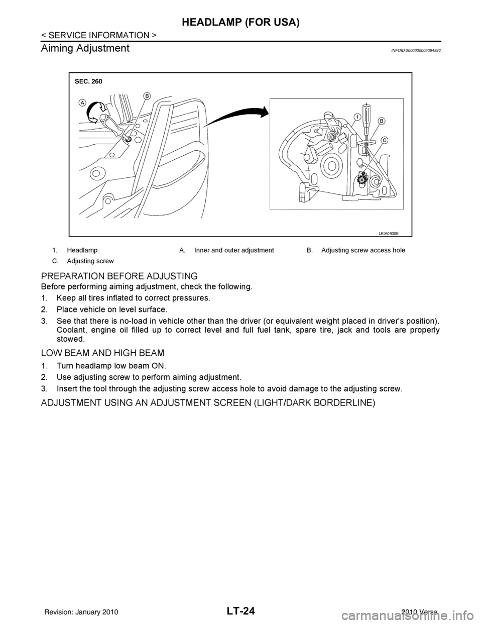
2. Use adjusting screw to perform aiming adjustment.
3. Insert the tool through the adjusting screw access hole to avoid damage to the adjusting screw.
ADJUSTMENT USING AN ADJUSTMENT SCREEN (LIGHT/DARK BORDERLINE)
1. Headlamp A. Inner and outer adjustment B. Adjusting screw access hole
C. Adjusting screw
LKIA0930E
Revision: January 20102010 Versa
Page 3033 of 3745
LT-38
< SERVICE INFORMATION >
HEADLAMP (FOR CANADA) - DAYTIME LIGHT SYSTEM -
Aiming Adjustment
INFOID:0000000005394908
PREPARATION BEFORE ADJUSTING
Before performing aiming adjustment, check the following.
1. Keep all tires inflated to correct pressures.
2. Place vehicle on level surface.
3. Set that there is no-load in vehicle other than the driv er (or equivalent weight placed in driver's position).
Coolant, engine oil filled up to correct level and full fuel tank, spare tire, jack and tools are properly
stowed.
LOW BEAM AND HIGH BEAM
1. Turn headlamp low beam ON.
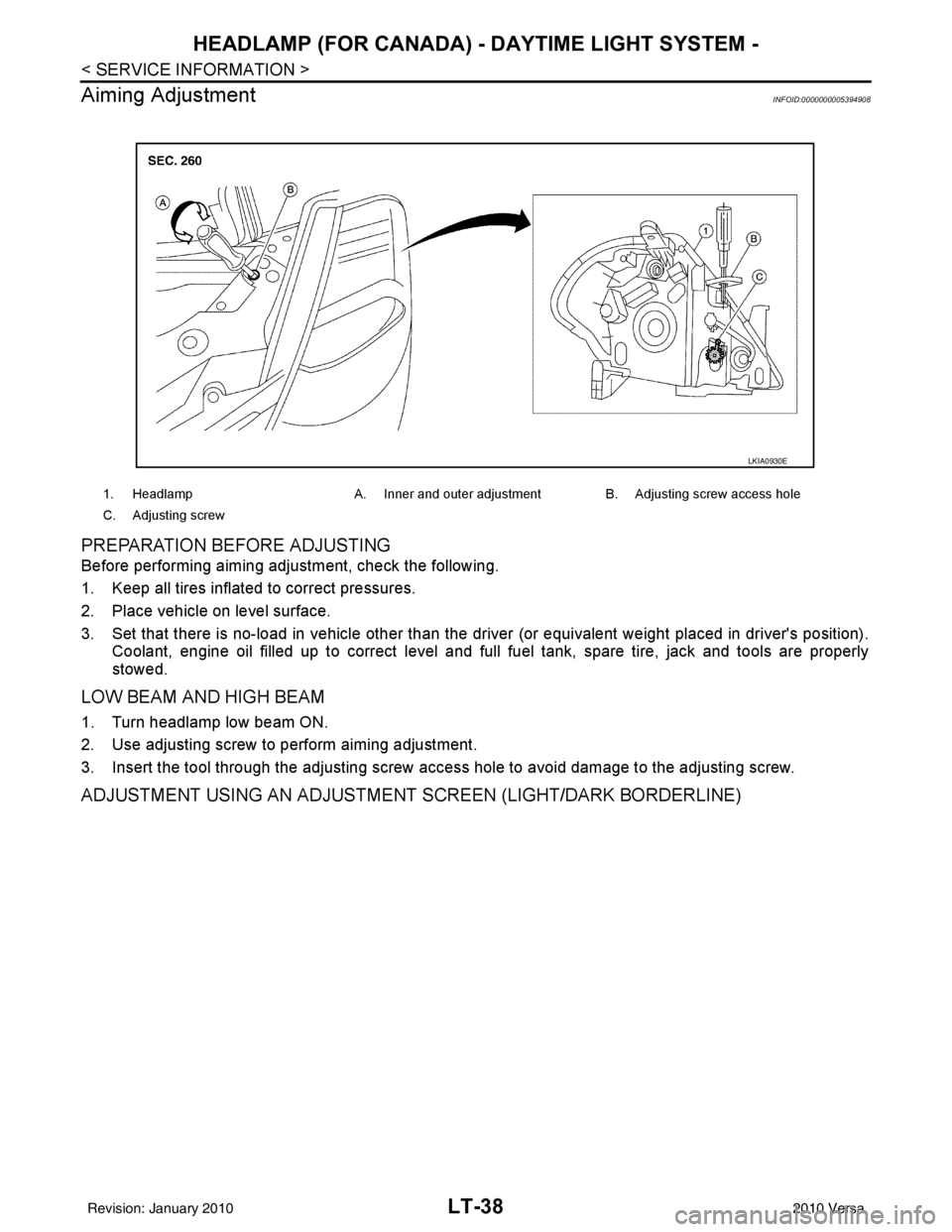
2. Use adjusting screw to perform aiming adjustment.
3. Insert the tool through the adjusting screw access hole to avoid damage to the adjusting screw.
ADJUSTMENT USING AN ADJUSTMENT SCREEN (LIGHT/DARK BORDERLINE)
1. Headlamp A. Inner and outer adjustment B. Adjusting screw access hole
C. Adjusting screw
LKIA0930E
Revision: January 20102010 Versa
Page 3044 of 3745
FRONT FOG LAMPLT-49
< SERVICE INFORMATION >
C
DE
F
G H
I
J
L
M A
B
LT
N
O P
1. Check continuity between front fog lamp harness connector and ground.
OK or NG
OK >> Replace IPDM E/R. Refer to PG-28, "Removal and
Installation of IPDM E/R" .
NG >> Repair harness or connector.
Aiming AdjustmentINFOID:0000000005394924
The front fog lamp is a semi-sealed beam type whic h uses a replaceable halogen bulb. Before performing
aiming adjustment, make sure of the following.
• Keep all tires inflated to correct pressure.
• Place vehicle on level surface.
• Set that there is no-load in vehicle other than the driver (or equivalent weight placed in driver’s position). Coolant, engine oil filled up to correct level and full fuel tank, spare tire, jack and tools are properly stowed.
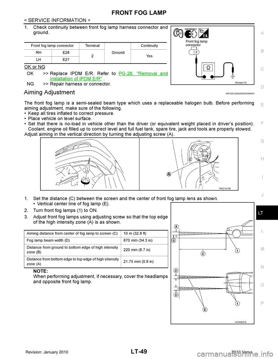
Adjust aiming in the vertical direction by turning the adjusting screw (A).
1. Set the distance (C) between the screen and the c enter of front fog lamp lens as shown.
• Vertical center line of fog lamp (E).
2. Turn front fog lamps (1) to ON.
3. Adjust front fog lamps using adjusting screw so that the top edge of the high intensity zone (A) is as shown.
NOTE:
When performing adjustment, if necessary, cover the headlamps
and opposite front fog lamp.
Front fog lamp connector Terminal
Ground Continuity
RH E28
2Y es
LH E27
PKIA6277E
PKIC1070E
Aiming distance from center of fog lamp to screen (C) 10 m (32.8 ft)
Fog lamp beam width (D) 870 mm (34.3 in)
Distance from ground to bottom edge of high intensity
zone (B) 220 mm (8.7 in)
Distance from bottom edge to top edge of high intensity
zone (A) 21.75 mm (0.9 in)
LKIA0931E
Revision: January 20102010 Versa
Page 3521 of 3745
REAR SUSPENSION ASSEMBLYRSU-7
< SERVICE INFORMATION >
C
DF
G H
I
J
K L
M A
B
RSU
N
O P
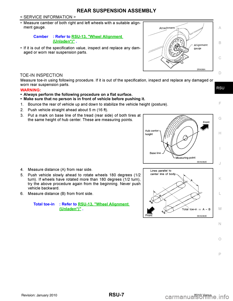
• Measure camber of both right and left wheels with a suitable align- ment gauge.
• If it is out of the specificati on value, inspect and replace any dam-
aged or worn rear suspension parts.
TOE-IN INSPECTION
Measure toe-in using following procedure. If it is out of the specification, inspect and replace any damaged or
worn rear suspension parts.
WARNING:
• Always perform the following procedure on a flat surface.
• Make sure that no person is in fron t of vehicle before pushing it.
1. Bounce the rear of vehicle up and down to stabilize the vehicle height (posture).
2. Push vehicle straight ahead about 5 m (16 ft).
3. Put a mark on base line of the tread (rear side) of both tires at the same height of hub center. These are measuring points.
4. Measure distance (A) from rear side.
5. Push vehicle slowly ahead to rotate wheels 180 degrees (1/2 turn). If wheels have rotated more than 180 degrees (1/2 turn),
try the above procedure again from the beginning. Never push
vehicle backward.
6. Measure distance (B) from front side. Camber : Refer to
RSU-13, "
Wheel Alignment
(Unladen*)" .
SRA096A
SEIA0362E
Total toe-in : Refer to RSU-13, "Wheel Alignment
(Unladen*)" .
SEIA0363E
Revision: January 20102010 Versa
Page 3523 of 3745
SHOCK ABSORBERRSU-9
< SERVICE INFORMATION >
C
DF
G H
I
J
K L
M A
B
RSU
N
O P
SHOCK ABSORBER
Removal and InstallationINFOID:0000000005397080
REMOVAL
1. Remove wheel and tire using power tool.
2. Remove wheel sensor from wheel hub and bearing assembly and rear suspension beam. Refer to BRC-
34 .
CAUTION:
Do not pull on wheel sensor harness.
3. Remove shock absorber mask from trunk side fini sher using a flat-bladed screwdriver. Refer to EI-54
.
CAUTION:
Wrap the tip of a screwdriver with cl oth to avoid damaging components.
4. Set jack under rear suspension beam.
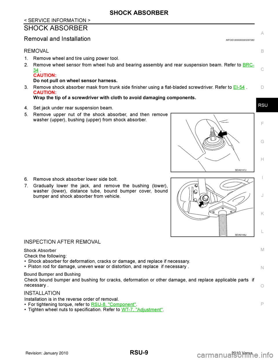
5. Remove upper nut of the shock absorber, and then remove washer (upper), bushing (upper) from shock absorber.
6. Remove shock absorber lower side bolt.
7. Gradually lower the jack, and remove the bushing (lower), washer (lower), distance tube, bound bumper cover, bound
bumper and shock absorber from vehicle.
INSPECTION AFTER REMOVAL
Shock Absorber
Check the following:
• Shock absorber for deformation, cracks or damage, and replace if necessary.
• Piston rod for damage, uneven wear or distortion, and replace if necessary .
Bound Bumper and Bushing
Check bound bumper and bushing for cracks, deformation or other damage, and replace applicable parts if
necessary .
INSTALLATION
Installation is in the reverse order of removal.
• For tightening torque, refer to RSU-8, "
Component".
• Tighten wheel nuts to specification. Refer to WT-7, "
Adjustment".
SEIA0147J
SEIA0146J
Revision: January 20102010 Versa