Page 523 of 658
6-14 For emergencies
6
5. Remove the wheel nuts with the wheel nut wrench, then
take the wheel off. 6. Clean out any mud, etc. on the hub surface (F), hub bolts
(G) or in the installation holes (H) in the wheel, and then
mount the spare tire.�
The jack should not be used for any purpose other
than to change a tire.
�
No one should be in your vehicle when using the
jack.
�
Do not start or run the engine while your vehicle is
on the jack.
�
Do not turn the raised wheel. The tires that are still
on the ground could turn and make your vehicle fall
off the jack. CAUTION
!�
Handle the wheel carefully when changing the tire,
to avoid scratching the wheel surface.WA R N I N G
!
BK0103001US.book 14 ページ 2009年8月20日 木曜日 午前10時45分
Page 525 of 658
6-16 For emergencies
6
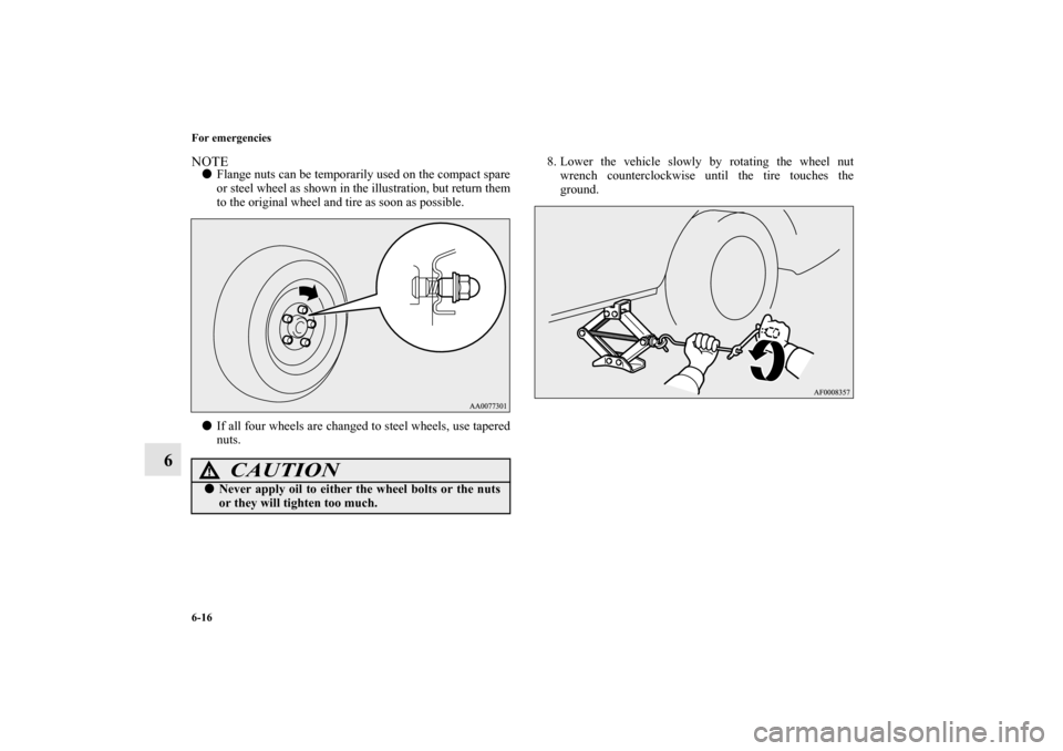
NOTE�
Flange nuts can be temporarily used on the compact spare
or steel wheel as shown in the illustration, but return them
to the original wheel and tire as soon as possible.
�
If all four wheels are changed to steel wheels, use tapered
nuts.8. Lower the vehicle slowly by rotating the wheel nut
wrench counterclockwise until the tire touches the
ground.
CAUTION
!�
Never apply oil to either the wheel bolts or the nuts
or they will tighten too much.
BK0103001US.book 16 ページ 2009年8月20日 木曜日 午前10時45分
Page 526 of 658
For emergencies
6-17
6
9. Tighten the nuts in the order shown in the illustration until
each nut has been tightened to the torque listed here.
65 to 80 ft-lb (88 to 108 Nm)
10. Lower the jack all the way and remove it.11. Check the tire inflation pressure. The recommended tire
pressure for your vehicle is listed on the tire and loading
information placard attached to the driver’s door sill as
shown in the illustration.
Refer to “Tire inflation pressures” on page 7-33.
CAUTION
!�
Never use your foot or a pipe extension to apply
added force to the wheel nut wrench when tighten-
ing the wheel nuts. If you do so, you can over-tighten
the wheel nuts and damage the wheel, wheel nuts
and hub bolts.
BK0103001US.book 17 ページ 2009年8月20日 木曜日 午前10時45分
Page 602 of 658
Vehicle care and maintenance
7-71
7
Front side-marker and parking lights (for vehi-
cles equipped with high intensity discharge head-
lights)
N00917300453
1. To create enough work space, turn the steering wheel all
the way in the direction opposite to the side you wish to
replace.
2. Remove the clips (A), and screw (B) or bolts (B) to turn
up the cover (C).Except for vehicles
with turbocharger
Vehicles with
turbocharger
BK0103001US.book 71 ページ 2009年8月20日 木曜日 午前10時45分
, hub bolts
(G) or in the installation holes (H) in")

10. Lower the jack all the")

N00917300453
1. To create enough work space, turn the stee")