Page 502 of 658

Comfort controls
5-95
5
�
In the following circumstances, moisture can form on
discs and inside the audio system, preventing normal
operation.
When there is high humidity (for example, when it is
raining).
When the temperature suddenly rises, such as right after
the heater is turned on in cold weather.
In this case, wait until the moisture has had time to dry
out.
�
When the CD player is subjected to violent vibrations,
such as during off-road driving, the tracking may not
work.
�
When storing compact discs, always store them in their
separate cases. Never place compact discs in direct sun-
light, or in any place where the temperature or humidity is
high.
�
Never touch the flat surface of the disc where there isn’t a
label. This will damage the disc surface and could affect
the sound quality. When handling a compact disc, always
hold it by the outer edge and the center hole.
�
To clean a disc, use a soft, clean, dry cloth. Wipe directly
from the center hole toward the outer edge. Do not wipe in
a circle. Never use any chemicals such as benzine, paint
thinner, a disc spray cleaner, or an anti-static agent on the
disc.
�
Do not use a ball point pen, felt pen, pencil, etc. to write
on the label surface of the disc.
BK0103001US.book 95 ページ 2009年8月20日 木曜日 午前10時45分
Page 512 of 658
 or a manual
trans")
For emergencies
6-3
6
3. You could be injured if the vehicles move. Set the parking
brake firmly on each vehicle. Put an automatic transaxle,
CVT or Twin Clutch SST in “P” (PARK) or a manual
transaxle in “N” (Neutral). Turn the ignition switch to the
“LOCK” position. NOTE�
Turn off all lights, heater, and other electrical loads. This
will avoid sparks and help save both batteries.
4. Make sure your battery electrolyte is at the proper level.
(Refer to “Checking battery electrolyte level” on page 7-
26.)5. For vehicles equipped with turbocharger, remove the air
duct and then the battery upper cover.
(Refer to “Removing and installing the battery upper
cover” on page 7-23.)
6. Connect one end of one jumper cable to the positive (+)
terminal of the discharged battery (A), and the other end
to the positive (+) terminal of the booster battery (B).
NOTE�
Open the terminal cover before connecting the jumper
cable to the positive terminal of the battery.
(Refer to “Disconnection and connection” on page 7-27.)
�
Use the proper cables suitable for the battery size.
Otherwise heat damage to the cables could result.
�
Check the jumper cables for damage and corrosion before
use.
WA R N I N G
!�
Turn the ignition switch to the “LOCK” position on
both vehicles. Make sure that the cables or your
clothes cannot be caught by the fan or drive belt.
Personal injury could result. WA R N I N G
!�
If the electrolyte fluid is not visible, or looks frozen,
DO NOT ATTEMPT JUMP STARTING!!
The battery might split open or explode if the tem-
perature is below the freezing point or if it is not
filled to the proper level.
BK0103001US.book 3 ページ 2009年8月20日 木曜日 午前10時45分
Page 543 of 658

7-12 Vehicle care and maintenance
7
To add coolant Use Mitsubishi Genuine Coolant or an equivalent.
Mitsubishi Genuine Coolant provides excellent protection
against corrosion and rust formation on all metals, including
aluminum, and prevents blockages in the radiator, heater, cyl-
inder head, engine block, etc.
If you need to add coolant often, or if the level in the reserve
tank does not drop when the engine cools, the cooling system
should be pressure-tested for leaks. Take your vehicle to an
authorized Mitsubishi Motors dealer or a repair facility of your
choice for testing.
*- Front of the vehicle
FULL
LOW Except for vehicles with turbocharger
Vehicles with turbocharger
FULL
LOW
CAUTION
!�
Do not use alcohol or methanol antifreeze or any
engine coolants that contain them. Using the wrong
antifreeze can corrode aluminum parts.
�
When you need to add coolant to the reserve tank,
use at least a 50 % concentration of ethylene-glycol
antifreeze in water. Do not overfill. Use a higher con-
centration (not over 60 %) when the outside temper-
ature is -31 °F (-35 °C) or lower. When the engine is
working very hard (for example, during mountain
driving and/or when the outside temperature is
high), use a 50 % concentration. You can check the
concentration level with a gauge from an automotive
supply store, or your authorized Mitsubishi Motors
dealer or service station can check it for you. Use
only high quality ethylene-glycol antifreeze coolant
that is made to prevent corrosion of all cooling sys-
tem metals.
BK0103001US.book 12 ページ 2009年8月20日 木曜日 午前10時45分
Page 583 of 658
7-52 Vehicle care and maintenance
7
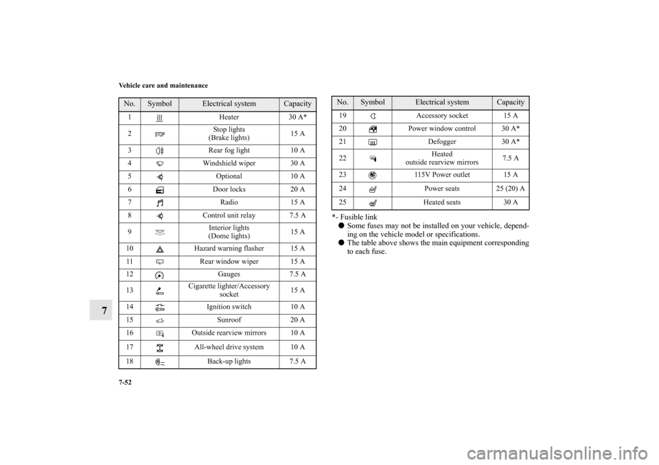
*- Fusible link�
Some fuses may not be installed on your vehicle, depend-
ing on the vehicle model or specifications.
�
The table above shows the main equipment corresponding
to each fuse.
No.
Symbol
Electrical system
Capacity
1 Heater 30 A*
2Stop lights
(Brake lights)15 A
3 Rear fog light 10 A
4 Windshield wiper 30 A
5 Optional 10 A
6 Door locks 20 A
7Radio15 A
8 Control unit relay 7.5 A
9Interior lights
(Dome lights)15 A
10 Hazard warning flasher 15 A
11 Rear window wiper 15 A
12 Gauges 7.5 A
13Cigarette lighter/Accessory
socket15 A
14 Ignition switch 10 A
15 Sunroof 20 A
16 Outside rearview mirrors 10 A
17 All-wheel drive system 10 A
18 Back-up lights 7.5 A
19 Accessory socket 15 A
20 Power window control 30 A*
21 Defogger 30 A*
22Heated
outside rearview mirrors7.5 A
23 115V Power outlet 15 A
24 Power seats 25 (20) A
25 Heated seats 30 ANo.
Symbol
Electrical system
Capacity
BK0103001US.book 52 ページ 2009年8月20日 木曜日 午前10時45分
Page 585 of 658

7-54 Vehicle care and maintenance
7
�
Some fuses may not be installed on your vehicle, depend-
ing on the vehicle model or specifications.
�
The table above shows the main equipment corresponding
to each fuse.
There are no 7.5 A, 25 A or 30 A spare fuses. If a fuse of one of
these capacities blows, replace it temporarily by borrowing one
of the fuses indicated below.
7.5 A: 10 A spare fuse
25 A: 20 A spare fuse
30 A: 30 A audio amplifier fuse
Replace the borrowed fuse with a fuse that has the correct
capacity as soon as possible.
17Headlight
(low/high beam) (right)20 A
*3
18Headlight
(low beam) (left)10 A
*4
19Headlight
(low beam) (right)10 A
*4
20
*1
ENG/POWER
10 A
*2
I/C SPRAY
21 Ignition coil 10 A
22
*1
ENG/POWER 20 A
Fuel line heater 25 A
22
*2
ENG/POWER 20 A
23 Fuel pump15 A
*1
20 A
*2
24 Starter
30 A
*5
25 — — —
26 Anti-lock braking system
40 A
*5
27 Anti-lock braking system
30 A
*5
28Air conditioning condenser fan
motor30 A
*5
29 Radiator fan motor
40 A
*5
No.
Symbol
Electrical system
Capacity
30 IOD IOD 30 A
31 Audio amplifier 30 A
32 Diesel 30 A
33 — Spare fuse 10 A
34 — Spare fuse 15 A
35 — Spare fuse 20 A
*1- Except for vehicles equipped with turbocharger
*2- Vehicles equipped with turbocharger
*3- For vehicles equipped with high intensity discharge head-
lights
*4- For vehicles without high intensity discharge headlights
*5- Fusible linkNo.
Symbol
Electrical system
Capacity
BK0103001US.book 54 ページ 2009年8月20日 木曜日 午前10時45分