Page 129 of 174

REFERENCEAT A GLANCE CONTROLS DRIVING TIPS MOBILITY
127
Replacing the bulb
1.Turn the lamp counterclockwise, arrow1,
and remove it, arrow2.
2.Push on the catch, arrow 1, and unplug the
connector, arrow2.
3.To insert the new bulb and replace the
cover, proceed in reverse order.
Turn signal indicators, parking lamps,
roadside parking lamps and fog lamps
Accessing the lamps via the wheel well
1Turn signal
2Parking/roadside parking/fog lamps
Replacing a turn signal bulb
21 watt bulb, PY 21 W
1.Turn in the wheel.2.Remove cover 1.
To do so, turn the cover counterclockwise.
3.Remove the inside cover.
To do so, turn the cover counterclockwise.
4.Screw out the bulb counterclockwise.
5.To insert the new bulb and replace the cov-
ers, proceed in reverse order.
Replacing a parking/roadside parking
lamp bulb
5watt bulb, W5W
1.Turn in the wheel.
2.Remove cover 2.
To do so, turn the cover counterclockwise.
3.Screw out the upper bulb counterclockwise.
4.To insert the new bulb and replace the
cover, proceed in reverse order.
Page 130 of 174
Replacing components
128
Replacing a fog lamp bulb
H8 bulb, 35 watts
1.Turn in the wheel.
2.Remove cover 2.
To do so, turn the cover counterclockwise.
3.Screw out the lower bulb counterclockwise.
4.To insert the new bulb and replace the
cover, proceed in reverse order.
Side turn signal indicators
5 watt bulb, W 5 W
1.Push the lamp with the ventilation grate for-
ward and remove.
2.Screw out the bulb holder counterclockwise.
3.Pull out and replace the bulb.
4.To insert the new bulb and replace the
cover, proceed in reverse order.
Tail lamps
1Brake lamp/tail lamp
21 watt/5 watt bulb, W 5 W
2Turn signal lamp
21 watt bulb, P 21 W
3Backup lamp
21 watt bulb, P 21 W
Lamp access
MINI:
Remove the cover from the sidewall of the cargo
bay.
MINI Convertible:
Move the convertible top to its uppermost posi-
tion, refer to Loading aid page95, and remove
the cover of the luggage compartment side wall.
Page 131 of 174

REFERENCEAT A GLANCE CONTROLS DRIVING TIPS MOBILITY
129
Changing
1.Screw out the desired bulb counterclock-
wise, arrows1.
Additional bulbs are located behind the
sidewall of the cargo bay, arrow 2.
2.To insert the new bulb and replace the
cover, proceed in reverse order.
Rear fog lamp*
21 watt bulb, P 21 W
Access to the lamp via the back or underside of
the bumper.
The illustration shows the fog lamp in the
bumper of the MINI Cooper.
1.Screw out the bulb holder counterclockwise.
2.Screw out and replace the bulb.
3.To insert the new bulb and bulb holder, pro-
ceed in reverse order.
License plate lamps
5 watt bulb, C 5 W1.Using a screwdriver, push the lamp to the
left in the tab of the lamp housing, arrow1.
2.Remove the lamp, arrow 2.
3.Replace the bulb.
4.Insert the lamp.
Center brake lamp
This lamp uses LED technology for operation. In
the event of a malfunction, contact your MINI
dealer or a workshop that has specially trained
personnel working in accordance with the spec-
ifications of your MINI manufacturer.
Repairing a flat tire
Safety measures in the event of a break-
down:
Park the vehicle as far as possible from moving
traffic and switch on the hazard warning flash-
ers.
Turn the steering wheel until the front wheels
are in the straight-ahead position and engage
the steering wheel lock. Engage the parking
brake and shift into 1st or reverse gear or place
the selector lever in position P.
All passengers should be outside the vehicle and
in a safe place, e.g. behind a guardrail.
Erect a warning triangle or warning flasher at the
appropriate distance if necessary. Comply with
all safety guidelines and regulations.<
In the event of a flat tire, different procedures
should be followed depending on the equip-
ment included in your vehicle:
Page 132 of 174

Replacing components
130
>MINI Mobility System, refer to the following
section
>Run-flat tires, page114
>Tire change with space-saver spare tire,
page132
MINI Mobility System with onboard
vehicle tool kit and tire change set*
Preparations
Use of the MINI Mobility System may be ineffec-
tive if the tire puncture measures approx. 1/8 in/
4 mm or more. Contact the nearest MINI dealer
if the tire cannot be made drivable with the
Mobility System.
Do not remove foreign bodies which have pen-
etrated the tire if possible.
Follow the instructions on using the Mobil-
ity System found on the compressor and
the sealant bottle.<
Remove the adhesive label for the speed limit
from the sealant bottle and affix it to the steer-
ing wheel.
The Mobility System with onboard vehicle tool
kit and tire change set
* is located under the
floor mat in the cargo bay.
1Sealant bottle
2Hexagon wrench
*
3Extractor hook*
4Vehicle jack*
5Wheel stud wrench
6Flat screwdriver/Phillips screwdriver, towing
eyelet
7Compressor
Sealant and compressor
1Sealant bottle and adhesive label with speed
limit
2Filling hose
Note the use-by date on the sealant bot-
tle.<
3Holder for the sealant bottle
4Compressor
5Plug and cable for the socket in the vehicle
interior, page88
6Connection hose to connect the compressor
and sealant bottle or the compressor and
wheel
7On/off switch
8Pressure gauge for indicating the tire infla-
tion pressure
9Release button for reducing the tire inflation
pressure
Connector, cable and connection hose are
stored in the compressor housing.
Using the Mobility System
To repair a tire puncture with the Mobility Sys-
tem, proceed as follows:
Page 133 of 174

REFERENCEAT A GLANCE CONTROLS DRIVING TIPS MOBILITY
131
>Filling the tire with sealant
>Distribute the sealant
>Correct the tire inflation pressure
Filling the tire with sealant
Proceed in the specified order; otherwise,
sealant may emerge under high pres-
sure.<
1.Shake the sealant bottle.
2.Pull the connection hose9 out of the com-
pressor housing fully and screw it onto the
connector of the sealant bottle. Make sure
that the hose is not kinked.
3.Insert the sealant bottle on the compressor
housing in an upright position.
4.Unscrew the dust cap from the valve of the
defective wheel and screw the filling hose 2
of the sealant bottle onto the valve.
5.Ensure that the compressor is switched off.
6.Insert the plug 3 into the lighter socket/
power socket in the vehicle interior,
page88.
7.With the engine running:
Switch on the compressor and let is run for
approx. 3 to 8 minutes to fill the tire with
sealant and achieve a tire inflation pressure
of approx. 26 psi/180 kPa.
When filling the tire with sealant, the
inflation pressure can briefly rise to
approx. 73 psi/500 kPa. Do not switch off
the compressor during this phase.<
Do not run the compressor for longer
than 10 minutes; otherwise, the
device will overheat and possibly be dam-
aged.<8.Switch off the compressor.
If an air pressure of 26 psi/180 kPa is not
reached:
1.Unscrew the filling hose 2 from the wheel
and drive the vehicle forward and backward
approx. 33 ft/10 m to distribute the liquid
sealant in the tire evenly.
2.Inflate the tire again with the compressor.
If an inflation pressure of 26 psi/180 kPa
still cannot be reached, the tire is too
heavily damaged. Please contact the nearest
MINI dealer.<
Stowing Mobility System
1.Unscrew filler hose2 of the sealant bottle
from the wheel.
2.Unscrew connecting hose of the
compressor9 from the sealant bottle.
3.Connect the filler hose2 of the sealant bot-
tle to the unoccupied connection on the
sealant bottle.
This prevents the rest of the sealant from
escaping from the bottle.
4.Wrap the empty sealant bottle in suitable
material to avoid dirtying the cargo bay.
5.Stow Mobility System back in the vehicle.
Distributing the sealant
Immediately drive approx. 3 mls/5 km to evenly
distribute the sealant.
Do not exceed speeds of 50 mph/
80 km/h.
If possible, do not drop below 10 mph/
20 km/h.<
Correcting the tire inflation pressure
1.After driving approx. 3 mls/5 km or ten min-
utes, stop at a suitable location.
2.Screw the connection hose 2 of the com-
pressor directly onto the tire valve.
3.Insert the plug 3 into the power socket in the
vehicle interior.
4.Correct the inflation pressure to 26 psi/
180 kPa. With the engine running:
Page 134 of 174

Replacing components
132
>To increase the inflation pressure: switch on
the compressor. To check the current infla-
tion pressure, switch off the compressor.
Do not run the compressor for longer
than 10 minutes; otherwise, the
device will overheat and possibly be dam-
aged.<
>To decrease the inflation pressure: press the
release button5.
If the tire cannot maintain the inflation
pressure, drive the vehicle again, refer to
Distributing the sealant. Then repeat steps
1to4.
If an inflation pressure of 26 psi/180 kPa still
cannot be reached, the tire is too heavily dam-
aged. Contact the nearest MINI dealer.<
Driving on
Do not exceed the permitted maximum
speed of 50 mph/80 km/h; doing so may
result in an accident.<
Replace the defective tire as soon as possible
and have the new wheel/tire assembly bal-
anced.
Have the Mobility System refilled.
Changing wheels
Space-saver spare tire*
To change a space-saver spare tire, proceed as
follows:
>Remove the space-saver spare tire,
page132
>Prepare for tire change, page133
>Jack up vehicle, page134
>Mount space-saver spare tire, page134
>Tighten lug bolts, page134
>Drive with space-saver spare tire, page133
Tire change set for a space-saver spare
tire*
On vehicles with a space-saver spare tire, the
tire change set with onboard tools is stored
under the floor mat in the cargo bay.
1Chock, folding
2Extractor hook
*
3Wheel stud wrench
4Vehicle jack
5Special wrench for removing the space-
saver spare tire
6Flat screwdriver/Phillips screwdriver
7Towing eyelet
8Lifting handle
The onboard vehicle tool kit includes a pouch
with a plastic bag in which you can place the
damaged wheel.
Removing the space-saver spare tire
The screw connection of the space-saver spare
tire is under the floor mat in the cargo bay, on
the base of the storage compartment for the tire
change set.
1.Unscrew the screw connection with the spe-
cial wrench.
2.Take out the cover panel.
Page 135 of 174

REFERENCEAT A GLANCE CONTROLS DRIVING TIPS MOBILITY
133
3.Screw the lifting handle from the onboard
vehicle tool kit onto the thread.
4.Raise the lifting handle slightly.
5.Squeeze the securing spring.
6.The space-saver spare tire is released and
must be held by the lifting handle.
7.Lower the space-saver spare tire with the
lifting handle.
8.Unscrew the lifting handle.
9.Pull the space-saver spare tire underneath
the vehicle out towards the rear.
10.Position the space-saver spare tire with the
valve facing upward.
11.Unscrew the valve extension from the valve
of the space-saver spare tire.12.Unscrew the dust cap from the extension
and place it on the valve of the space-saver
spare tire.
Due to its different dimensions, the dam-
aged wheel cannot be placed in the recess
for the space-saver spare tire.<
Driving with the space-saver spare tire
Drive cautiously and do not exceed a
speed of 50 mph/80 km/h. Changes may
occur in vehicle handling such as lower track sta-
bility during braking, longer braking distances
and changes in self-steering properties when
close to the handling limit. These properties are
more noticeable with winter tires.<
Only one space-saver spare tire may be
mounted at one time. Mount a wheel and
tire of the original size as soon as possible, to
avoid any safety risks.<
Check the tire inflation pressure at the ear-
liest opportunity and correct it if neces-
sary. Replace the defective tire as soon as possi-
ble and have the new wheel/tire assembly
balanced.<
Preparing for a tire change
Observe the safety precautions regarding
flat tires on page129.<
Additional safety measures when chang-
ing tires:
Only change the tire when parked on a surface
that is level, firm and not slippery.
The vehicle or the jack could slip sideways on
soft or slippery support surfaces, such as snow,
ice, flagstones, etc.
Do not use a wooden block or similar object as a
support base for the jack, as this would prevent
it from extending to its full support height and
reduce its load-carrying capacity.
Do not lie under the vehicle or start the engine
when the vehicle is supported by the jack; other-
wise, there is a risk of fatal injury.<
Page 136 of 174

Replacing components
134
1.Place the foldable chock* behind the front
wheel on the other side of the vehicle or in
front of the wheel if the vehicle is on an
incline. If the wheel is changed on a surface
with a more severe slope, take additional
precautions to secure the vehicle from roll-
ing.
2.Uncover the lug bolts if necessary.
3.Loosen the lug bolts by a half turn.
Jacking up the vehicle
The vehicle jack is designed for changing
wheels only. Do not attempt to raise
another vehicle model with it or to raise any load
of any kind. To do so could cause accidents and
personal injury.<
1.Place the jack at the jacking point closest to
the wheel.
The jack base must be perpendicular to the
surface beneath the jacking point.
2.During jacking up, insert the jack head in the
square recess of the jacking point.
3.Jack the vehicle up until the wheel you are
changing is raised off the ground.
Mounting the space-saver spare tire
1.Unscrew the lug bolts and remove the
wheel.
2.Remove accumulations of mud or dirt from
the mounting surfaces of the wheel and
hub. Clean the lug bolts.
3.Lift the new wheel into place.
4.Screw at least two lug bolts finger-tight into
opposite bolt holes.
5.Screw in the remaining bolts.
6.Tighten all the lug bolts firmly in a diagonal
pattern.
7.Lower the vehicle.
8.Remove the jack.
Tightening the lug bolts
Tighten the lug bolts in a diagonal pattern.
Immediately have the wheels checked
with a calibrated torque wrench to ensure
that the lug bolts are firmly seated. Otherwise,
incorrectly tightened lug bolts can present a
safety hazard.<
Tightening torque: 103.3 lb ft or 140 Nm.
Replace the defective tire as soon as possible
and have the new wheel/tire assembly bal-
anced.
Vehicle battery
Maintenance
The battery is 100 % maintenance-free, the
electrolyte will last for the life of the battery
when the vehicle is operated in a temperate cli-
mate.
Battery replacement
Only use vehicle batteries that have been
approved for your vehicle by the manu-
facturer; otherwise, the vehicle could be dam-
aged and systems or functions may not be fully
available.<
 1
1 2
2 3
3 4
4 5
5 6
6 7
7 8
8 9
9 10
10 11
11 12
12 13
13 14
14 15
15 16
16 17
17 18
18 19
19 20
20 21
21 22
22 23
23 24
24 25
25 26
26 27
27 28
28 29
29 30
30 31
31 32
32 33
33 34
34 35
35 36
36 37
37 38
38 39
39 40
40 41
41 42
42 43
43 44
44 45
45 46
46 47
47 48
48 49
49 50
50 51
51 52
52 53
53 54
54 55
55 56
56 57
57 58
58 59
59 60
60 61
61 62
62 63
63 64
64 65
65 66
66 67
67 68
68 69
69 70
70 71
71 72
72 73
73 74
74 75
75 76
76 77
77 78
78 79
79 80
80 81
81 82
82 83
83 84
84 85
85 86
86 87
87 88
88 89
89 90
90 91
91 92
92 93
93 94
94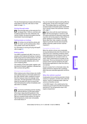 95
95 96
96 97
97 98
98 99
99 100
100 101
101 102
102 103
103 104
104 105
105 106
106 107
107 108
108 109
109 110
110 111
111 112
112 113
113 114
114 115
115 116
116 117
117 118
118 119
119 120
120 121
121 122
122 123
123 124
124 125
125 126
126 127
127 128
128 129
129 130
130 131
131 132
132 133
133 134
134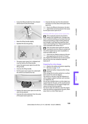 135
135 136
136 137
137 138
138 139
139 140
140 141
141 142
142 143
143 144
144 145
145 146
146 147
147 148
148 149
149 150
150 151
151 152
152 153
153 154
154 155
155 156
156 157
157 158
158 159
159 160
160 161
161 162
162 163
163 164
164 165
165 166
166 167
167 168
168 169
169 170
170 171
171 172
172 173
173