2010 MERCEDES-BENZ R320 light
[x] Cancel search: lightPage 192 of 364
Expanding cargo volume in part
Folding third-row seats
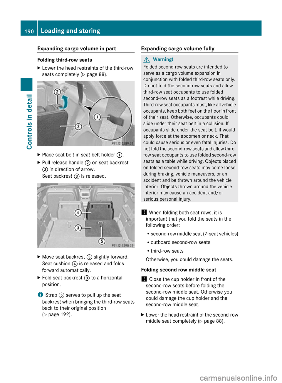
X
Lower the head restraints of the third-row
seats completely ( Y page 88).X
Place seat belt in seat belt holder :.
X Pull release handle ; on seat backrest
= in direction of arrow.
Seat backrest = is released. X
Move seat backrest = slightly forward.
Seat cushion ? is released and folds
forward automatically.
X Fold seat backrest = to a horizontal
position.
i Strap A serves to pull up the seat
backrest when bringing the third-row seats
back to their original position
(Y page 192). Expanding cargo volume fully G
Warning!
Folded second-row seats are intended to
serve as a cargo volume expansion in
conjunction with folded third-row seats only.
Do not fold the second-row seats and allow
third-row seat occupants to use folded
second-row seats as a footrest while driving.
Third-row seat occupants must, like all vehicle
occupants, keep both feet on the floor in front
of their seat. Otherwise, occupants could
slide under their seat belt in a collision. If
occupants slide under the seat belt, it would
apply force at the abdomen or neck. That
could cause serious or even fatal injuries. Do
not fold the second-row seats and allow third-
row seat occupants to use folded second-row
seats as a table while driving. Objects placed
on folded second-row seats may come loose
during braking, vehicle maneuvers, or an
accident and be thrown around the vehicle
interior. Objects thrown around the vehicle
interior may cause an accident and/or
serious personal injury.
! When folding both seat rows, it is
important that you fold the seats in the
following order:
R second-row middle seat (7-seat vehicles)
R outboard second-row seats
R third-row seats
Otherwise, you could damage the seats.
Folding second-row middle seat
! Close the cup holder in front of the
second-row seats before folding the
second-row middle seat. Otherwise you
could damage the cup holder and the
second-row middle seat.
X Lower the head restraint of the second-row
middle seat completely ( Y page 88).190
Loading and storingControls in detail
251_AKB; 4; 52, en-US
d2ureepe,
Version: 2.11.8.1 2009-03-23T09:22:52+01:00 - Seite 190
Page 200 of 364
Keep compartment lids closed. This will help
to prevent stored objects from being thrown
about and injuring vehicle occupants during
R
braking
R vehicle maneuvers
R an accident
Glove box Depending on vehicle equipment, an AUX
socket or a media interface is located in the
glove box. For information on Audio AUX
mode or on media interface, see separate
COMAND system operating instructions.
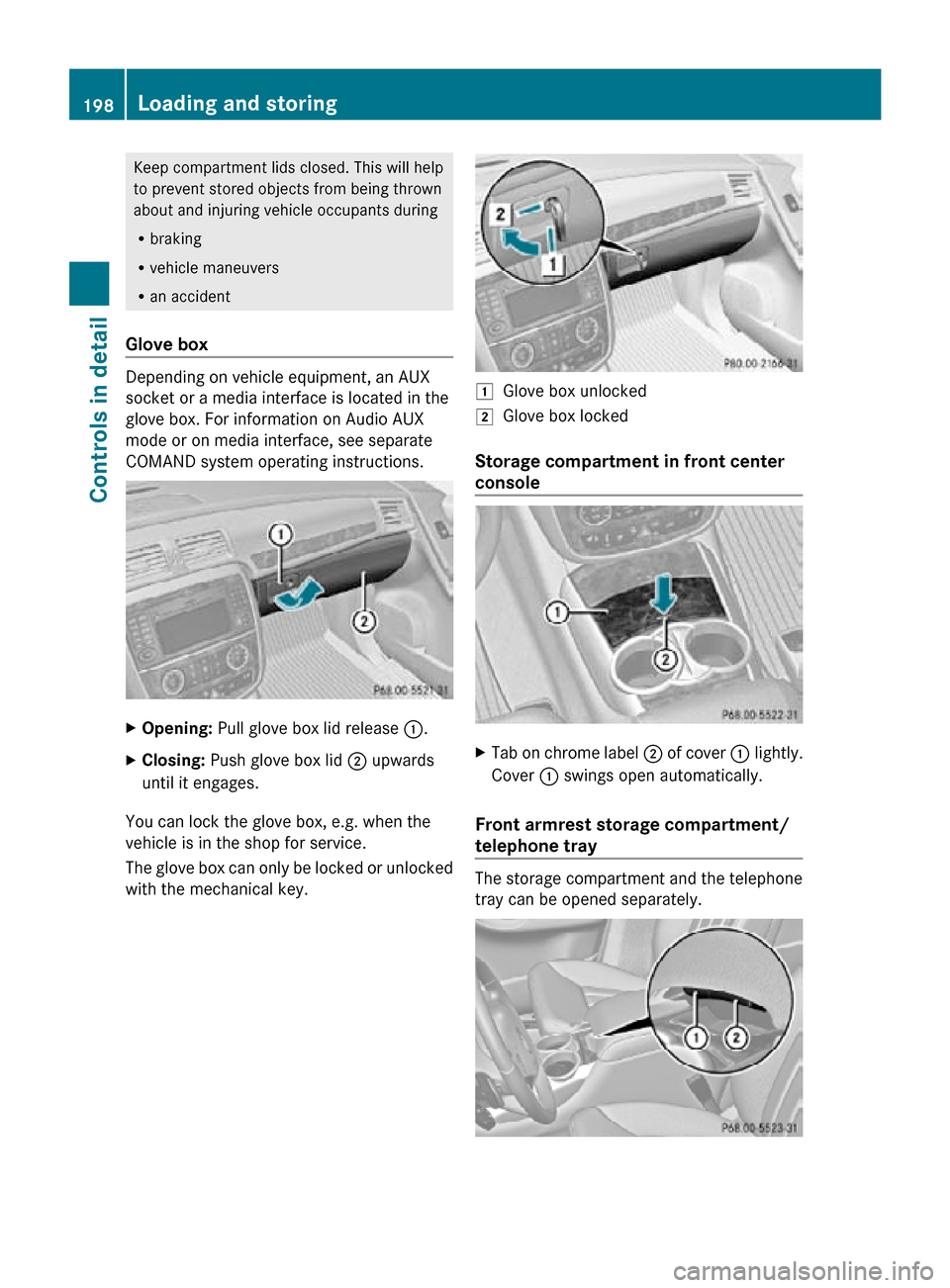
X
Opening: Pull glove box lid release :.
X Closing: Push glove box lid ; upwards
until it engages.
You can lock the glove box, e.g. when the
vehicle is in the shop for service.
The glove box can only be locked or unlocked
with the mechanical key. 1
Glove box unlocked
2 Glove box locked
Storage compartment in front center
console X
Tab on chrome label ; of cover : lightly.
Cover : swings open automatically.
Front armrest storage compartment/
telephone tray The storage compartment and the telephone
tray can be opened separately.198
Loading and storingControls in detail
251_AKB; 4; 52, en-US
d2ureepe,
Version: 2.11.8.1 2009-03-23T09:22:52+01:00 - Seite 198
Page 207 of 364
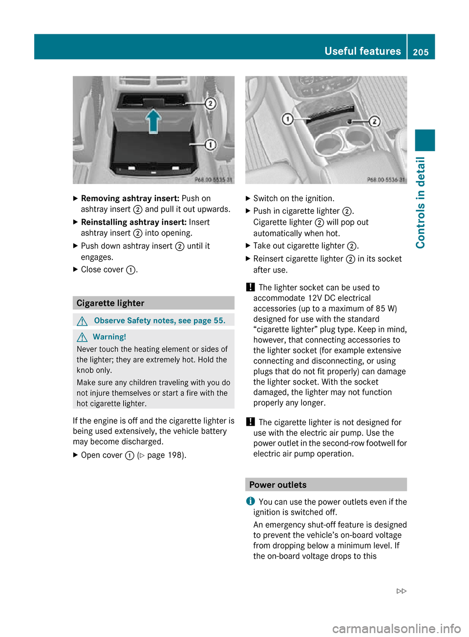
X
Removing ashtray insert: Push on
ashtray insert ; and pull it out upwards.
X Reinstalling ashtray insert: Insert
ashtray insert ; into opening.
X Push down ashtray insert ; until it
engages.
X Close cover :. Cigarette lighter
G
Observe Safety notes, see page 55. G
Warning!
Never touch the heating element or sides of
the lighter; they are extremely hot. Hold the
knob only.
Make sure any children traveling with you do
not injure themselves or start a fire with the
hot cigarette lighter.
If the engine is off and the cigarette lighter is
being used extensively, the vehicle battery
may become discharged.
X Open cover : (Y page 198). X
Switch on the ignition.
X Push in cigarette lighter ;.
Cigarette lighter ; will pop out
automatically when hot.
X Take out cigarette lighter ;.
X Reinsert cigarette lighter ; in its socket
after use.
! The lighter socket can be used to
accommodate 12V DC electrical
accessories (up to a maximum of 85 W)
designed for use with the standard
“cigarette lighter” plug type. Keep in mind,
however, that connecting accessories to
the lighter socket (for example extensive
connecting and disconnecting, or using
plugs that do not fit properly) can damage
the lighter socket. With the socket
damaged, the lighter may not function
properly any longer.
! The cigarette lighter is not designed for
use with the electric air pump. Use the
power outlet in the second-row footwell for
electric air pump operation. Power outlets
i You can use the power outlets even if the
ignition is switched off.
An emergency shut-off feature is designed
to prevent the vehicle’s on-board voltage
from dropping below a minimum level. If
the on-board voltage drops to this Useful features
205Controls in detail
251_AKB; 4; 52, en-US
d2ureepe, Version: 2.11.8.1 2009-03-23T09:22:52+01:00 - Seite 205 Z
Page 216 of 364
X
Step 4: Using both hands, simultaneously
press hand-held remote control button B
and the desired signal transmitter button
(;, = or ?). Do not release the buttons
until step 5 is completed.
Indicator
lamp : will flash, first slowly and
then rapidly.
i Indicator lamp : flashes immediately
the first time the signal transmitter button
is programmed. If this button has already
been programmed, the indicator lamp will
start flashing after 20 seconds.
X Step 5: After indicator lamp : changes
from a slow to a rapidly flashing light,
release the hand-held remote control
button and the signal transmitter button.
X Step 6: Press and hold the just-trained
signal
transmitter button (;, = or ?) and
observe indicator lamp :.
If indicator lamp : stays on constantly,
programming is complete and your device
should activate when the respective signal
transmitter button ( ;, = or ?) is pressed
and released.
i If indicator lamp : flashes rapidly for
approximately
2 seconds and then turns to
a constant light, continue with
programming steps 8 through 12 as your
garage door opener may be equipped with
the “rolling code” feature.
X Step 7: To program the remaining two
signal
transmitter buttons, repeat the steps
above starting with step 3.
Rolling code programming
To
train a garage door opener (or other rolling
code devices) with the rolling code feature,
follow these instructions after completing the
“Programming” portion (steps 1 through 6) of
this text. For your convenience and to
complete the procedure faster, you might
want to have someone assist you. X
Step 8:
Locate the “training” button on the
garage door opener motor head unit.
i Exact
location and color of the button may
vary by garage door opener brand.
Depending on manufacturer, the “training”
button may also be referred to as “learn” or
“smart” button. If there is difficulty locating
the transmitting button, refer to the garage
door opener Operator’s Manual.
X Step 9: Press the “training” button on the
garage door opener motor head unit.
The “training light” is activated.
You have 30 seconds to initiate the
following two steps.
X Step 10: Return to the vehicle and firmly
press, hold for 2 seconds and release the
programmed
signal transmitter button (;,
= or ?).
X Step 11: Press, hold for 2 seconds and
release same signal transmitter button a
second time to complete the training
process.
i Some garage door openers (or other
rolling
code equipped devices) may require
you to press, hold for 2 seconds and
release the same signal transmitter button
a third time to complete the training
process.
X Step 12: Confirm the garage door
operation by pressing the programmed
signal transmitter button ( ;, = or ?).
X Step 13: To program the remaining two
signal
transmitter buttons, repeat the steps
above starting with step 3.
Gate operator/Canadian programming
Canadian radio-frequency laws require
transmitter signals to “time-out” (or quit)
after several seconds of transmission which
may not be long enough for the integrated
signal
transmitter to pick up the signal during
programming. Similar to this Canadian law,
some U.S. gate operators are designed to
“time-out” in the same manner. 214
Useful features
Controls in detail
251_AKB; 4; 52, en-US
d2ureepe,
Version: 2.11.8.1 2009-03-23T09:22:52+01:00 - Seite 214
Page 224 of 364
i
Leaving the engine running and the fuel
filler cap open can cause the yellow fuel
tank
reserve warning lamp to flash and the
malfunction indicator lamp ! (USA
only) or ; (Canada only) to illuminate.
For more information, see also “Practical
hints” (Y page 305).
X Remove the SmartKey from the starter
switch.
KEYLESS-GO: Open the driver’s door (this
puts the starter switch in position 0, same
as with the SmartKey removed from the
starter switch). The driver’s door then can
be closed again.
X Opening: Press fuel filler flap : at the
point indicated by the arrow.
X Turn fuel filler cap ; counterclockwise.
X Take off fuel filler cap ;.
! The fuel filler cap is tethered to the fuel
filler neck. Do not drop the cap. It could
damage the vehicle paint finish.
X Set fuel filler cap ; on fuel filler flap :.
X Fully insert filler nozzle unit and refuel.
X Only fill your tank until the filler nozzle unit
cuts out – do not top off or overfill .
X Closing: Turn fuel filler cap ; clockwise
until it audibly engages.
X Close fuel filler flap :.
Low outside temperatures (diesel
engine) !
Do not fill the tank with gasoline. Do not
blend
diesel fuel with gasoline or kerosene.
The fuel system and engine will otherwise
be damaged, which is not covered by the
Mercedes-Benz Limited Warranty.
To prevent malfunctions, diesel fuel with
improved cold flow characteristics is offered
in the winter months. Check with your fuel
retailer. Check regularly and before a long trip
For information on quantities and
requirements
of operating agents, see “Fuels,
coolants, lubricants, etc.” (Y page 350).
Check the following:
R Engine oil level ( Y page 224)
R Tire inflation pressure ( Y page 230)
R Coolant level ( Y page 225)
R Vehicle lighting ( Y page 313)
R Washer system and headlamp cleaning
system (Y page 226)
R Brake fluid ( Y page 227) Engine compartment
Hood
G
Warning!
Do not pull the release lever while the vehicle
is in motion. Otherwise the hood could be
forced open by passing air flow.
This
could cause the hood to come loose and
injure you and/or others.
Opening G
Warning!
Do not open the hood when the engine is
overheated. You could be seriously injured.
Observe the coolant temperature display to
determine whether the engine may be
overheated. If you see flames or smoke
coming from the engine compartment, move
away from the vehicle. Wait until the engine
has cooled. If necessary, call the fire
department. G
Warning!
You could be injured when the hood is open –
even when the engine is turned off.
Parts of the engine can become very hot. To
prevent
burns, let the engine cool completely
before touching any components on the 222
Engine compartment
Operation
251_AKB; 4; 52, en-US
d2ureepe,
Version: 2.11.8.1 2009-03-23T09:22:52+01:00 - Seite 222
Page 244 of 364
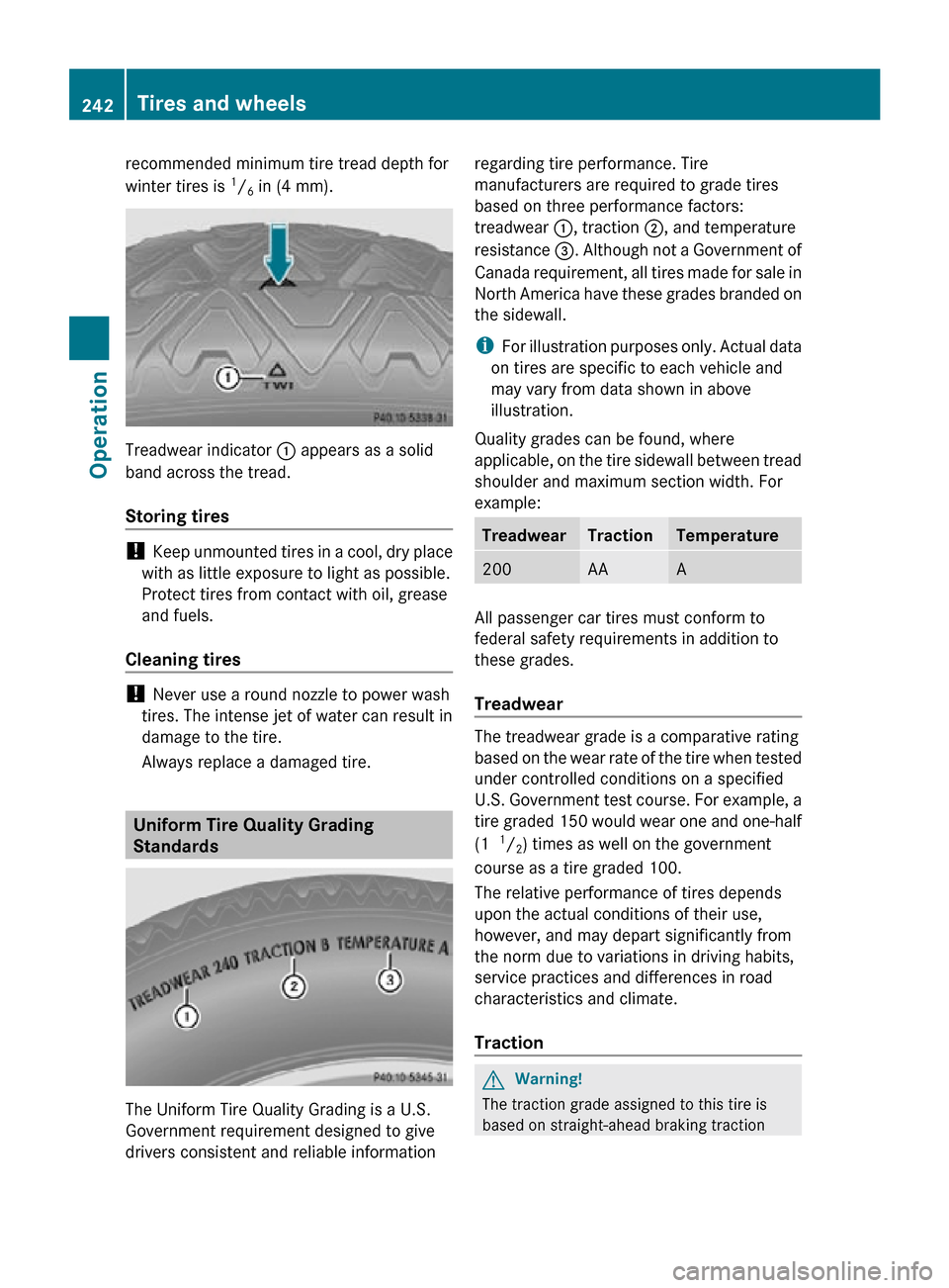
recommended minimum tire tread depth for
winter tires is
1
/ 6 in (4 mm). Treadwear indicator
: appears as a solid
band across the tread.
Storing tires !
Keep unmounted tires in a cool, dry place
with as little exposure to light as possible.
Protect tires from contact with oil, grease
and fuels.
Cleaning tires !
Never use a round nozzle to power wash
tires. The intense jet of water can result in
damage to the tire.
Always replace a damaged tire. Uniform Tire Quality Grading
Standards
The Uniform Tire Quality Grading is a U.S.
Government requirement designed to give
drivers consistent and reliable information regarding tire performance. Tire
manufacturers are required to grade tires
based on three performance factors:
treadwear
:, traction ;, and temperature
resistance =. Although not a Government of
Canada requirement, all tires made for sale in
North America have these grades branded on
the sidewall.
i For illustration purposes only. Actual data
on tires are specific to each vehicle and
may vary from data shown in above
illustration.
Quality grades can be found, where
applicable, on the tire sidewall between tread
shoulder and maximum section width. For
example: Treadwear Traction Temperature
200 AA A
All passenger car tires must conform to
federal safety requirements in addition to
these grades.
Treadwear
The treadwear grade is a comparative rating
based on the wear rate of the tire when tested
under controlled conditions on a specified
U.S. Government test course. For example, a
tire graded 150 would wear one and one-half
(1
1
/ 2) times as well on the government
course as a tire graded 100.
The relative performance of tires depends
upon the actual conditions of their use,
however, and may depart significantly from
the norm due to variations in driving habits,
service practices and differences in road
characteristics and climate.
Traction G
Warning!
The traction grade assigned to this tire is
based on straight-ahead braking traction 242
Tires and wheelsOperation
251_AKB; 4; 52, en-US
d2ureepe,
Version: 2.11.8.1 2009-03-23T09:22:52+01:00 - Seite 242
Page 247 of 364
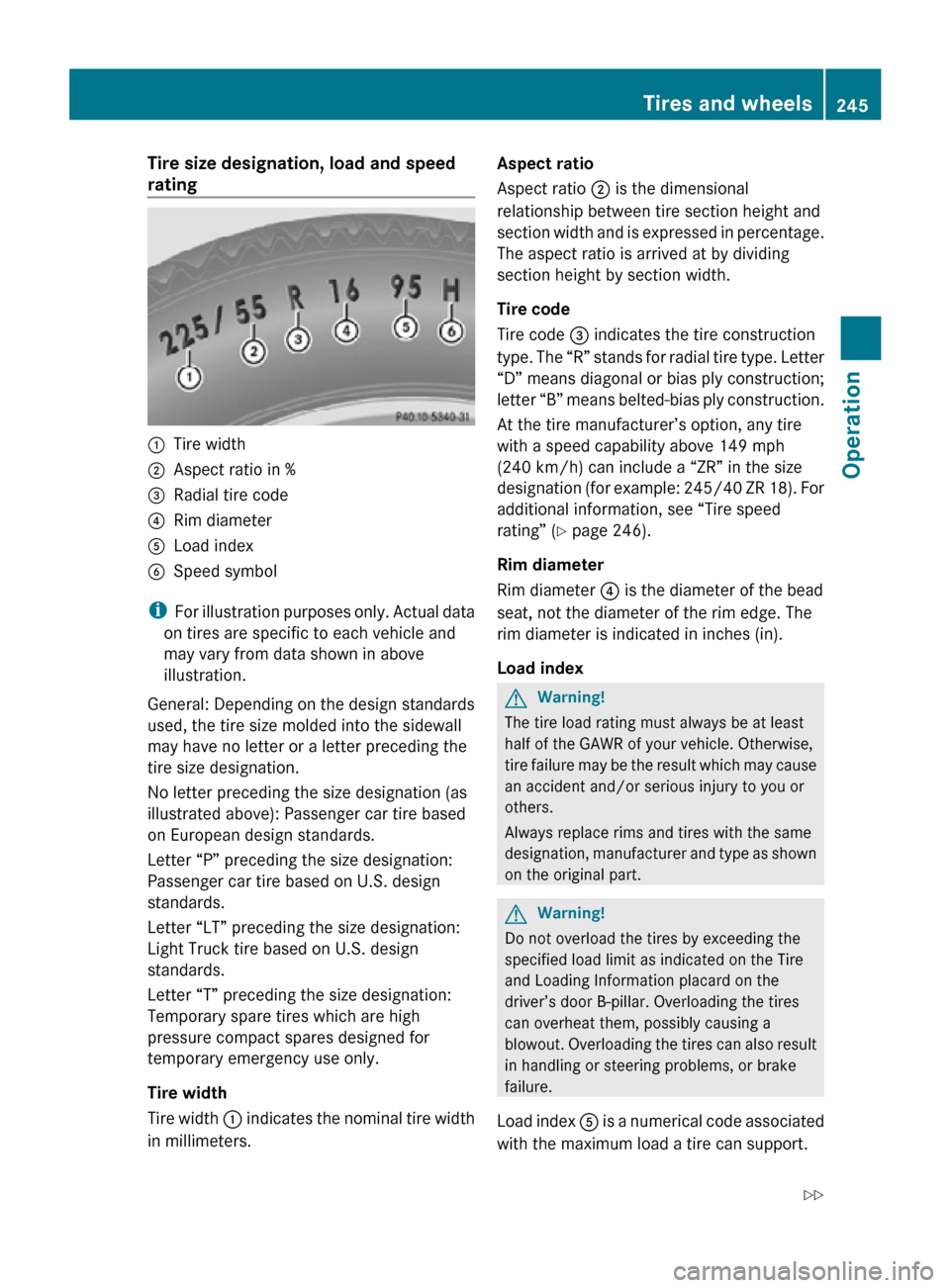
Tire size designation, load and speed
rating
:
Tire width
; Aspect ratio in %
= Radial tire code
? Rim diameter
A Load index
B Speed symbol
i For illustration purposes only. Actual data
on tires are specific to each vehicle and
may vary from data shown in above
illustration.
General: Depending on the design standards
used, the tire size molded into the sidewall
may have no letter or a letter preceding the
tire size designation.
No letter preceding the size designation (as
illustrated above): Passenger car tire based
on European design standards.
Letter “P” preceding the size designation:
Passenger car tire based on U.S. design
standards.
Letter “LT” preceding the size designation:
Light Truck tire based on U.S. design
standards.
Letter “T” preceding the size designation:
Temporary spare tires which are high
pressure compact spares designed for
temporary emergency use only.
Tire width
Tire width : indicates the nominal tire width
in millimeters. Aspect ratio
Aspect ratio
; is the dimensional
relationship between tire section height and
section width and is expressed in percentage.
The aspect ratio is arrived at by dividing
section height by section width.
Tire code
Tire code = indicates the tire construction
type. The “R” stands for radial tire type. Letter
“D” means diagonal or bias ply construction;
letter “B” means belted-bias ply construction.
At the tire manufacturer’s option, any tire
with a speed capability above 149 mph
(240 km/h) can include a “ZR” in the size
designation (for example: 245/40 ZR 18). For
additional information, see “Tire speed
rating” (Y page 246).
Rim diameter
Rim diameter ? is the diameter of the bead
seat, not the diameter of the rim edge. The
rim diameter is indicated in inches (in).
Load index G
Warning!
The tire load rating must always be at least
half of the GAWR of your vehicle. Otherwise,
tire failure may be the result which may cause
an accident and/or serious injury to you or
others.
Always replace rims and tires with the same
designation, manufacturer and type as shown
on the original part. G
Warning!
Do not overload the tires by exceeding the
specified load limit as indicated on the Tire
and Loading Information placard on the
driver’s door B-pillar. Overloading the tires
can overheat them, possibly causing a
blowout. Overloading the tires can also result
in handling or steering problems, or brake
failure.
Load index A is a numerical code associated
with the maximum load a tire can support. Tires and wheels
245Operation
251_AKB; 4; 52, en-US
d2ureepe, Version: 2.11.8.1 2009-03-23T09:22:52+01:00 - Seite 245 Z
Page 249 of 364
Index Speed rating
H M+S
14 up to 130 mph (210 km/h)
V M+S
14 up to 149 mph (240 km/h)
i
Not all M+S rated tires provide special
winter performance. Make sure the tires
you use show M+S and the mountain/
snowflakeimarking on the tire
sidewall. These tires meet specific snow
traction performance requirements of the
Rubber Manufacturers Association (RMA)
and the Rubber Association of Canada
(RAC) and have been designed specifically
for use in snow conditions.
An electronic speed limiter prevents your
vehicle from exceeding a speed of 130 mph
(210 km/h).
The factory equipped tires on your vehicle
may have a tire speed rating above the
maximum speed permitted by the electronic
speed limiter.
Make sure your tires have the required tire
speed rating as specified for your vehicle in
the “Technical data” section ( Y page 347),
for example when purchasing new tires.
If you are uncertain about the correct reading
of the information given on a tire’s sidewall,
any authorized Mercedes-Benz Center will be
glad to assist you. Load identification
i
For illustration purposes only. Actual data
on tires are specific to each vehicle and
may vary from data shown in above
illustration.
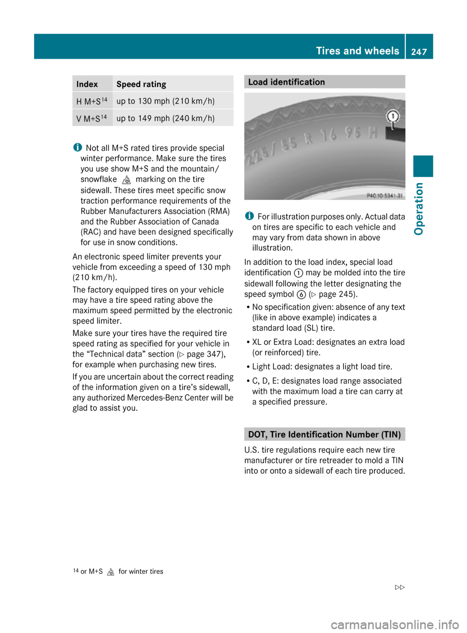
In addition to the load index, special load
identification : may be molded into the tire
sidewall following the letter designating the
speed symbol B (Y page 245).
R No specification given: absence of any text
(like in above example) indicates a
standard load (SL) tire.
R XL or Extra Load: designates an extra load
(or reinforced) tire.
R Light Load: designates a light load tire.
R C, D, E: designates load range associated
with the maximum load a tire can carry at
a specified pressure. DOT, Tire Identification Number (TIN)
U.S. tire regulations require each new tire
manufacturer or tire retreader to mold a TIN
into or onto a sidewall of each tire produced.
14 or M+S ifor winter tires Tires and wheels
247Operation
251_AKB; 4; 52, en-US
d2ureepe, Version: 2.11.8.1 2009-03-23T09:22:52+01:00 - Seite 247 Z