2010 MERCEDES-BENZ R320 length
[x] Cancel search: lengthPage 92 of 364
X
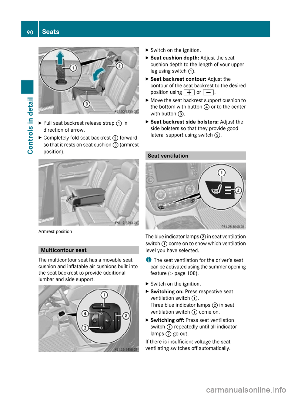
Pull seat backrest release strap : in
direction of arrow.
X Completely fold seat backrest ; forward
so that it rests on seat cushion = (armrest
position). Armrest position
Multicontour seat
The multicontour seat has a movable seat
cushion and inflatable air cushions built into
the seat backrest to provide additional
lumbar and side support. X
Switch on the ignition.
X Seat cushion depth: Adjust the seat
cushion depth to the length of your upper
leg using switch :.
X Seat backrest contour: Adjust the
contour of the seat backrest to the desired
position using W or X.
X Move the seat backrest support cushion to
the bottom with button ? or to the center
with button =.
X Seat backrest side bolsters: Adjust the
side bolsters so that they provide good
lateral support using switch ;. Seat ventilation
The blue indicator lamps
; in seat ventilation
switch : come on to show which ventilation
level you have selected.
i The seat ventilation for the driver’s seat
can be activated using the summer opening
feature ( Y page 108).
X Switch on the ignition.
X Switching on: Press respective seat
ventilation switch :.
Three blue indicator lamps ; in seat
ventilation switch : come on.
X Switching off: Press seat ventilation
switch : repeatedly until all indicator
lamps ; go out.
If there is insufficient voltage the seat
ventilating switches off automatically. 90
SeatsControls in detail
251_AKB; 4; 52, en-US
d2ureepe,
Version: 2.11.8.1 2009-03-23T09:22:52+01:00 - Seite 90
Page 122 of 364
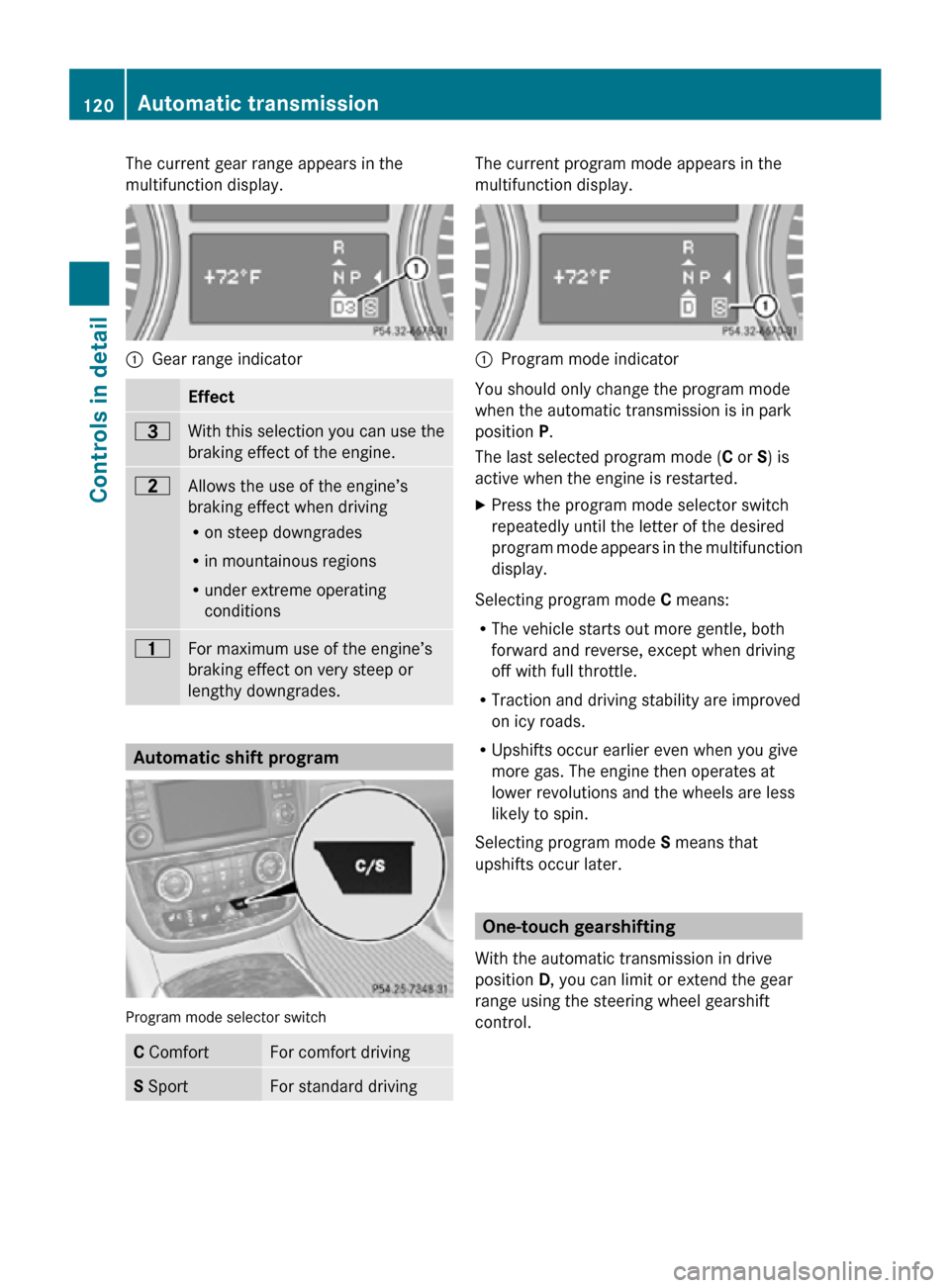
The current gear range appears in the
multifunction display.
:
Gear range indicator Effect
=
With this selection you can use the
braking effect of the engine.
5
Allows the use of the engine’s
braking effect when driving
R
on steep downgrades
R in mountainous regions
R under extreme operating
conditions 4
For maximum use of the engine’s
braking effect on very steep or
lengthy downgrades.
Automatic shift program
Program mode selector switch
C Comfort For comfort driving
S Sport For standard driving The current program mode appears in the
multifunction display.
:
Program mode indicator
You should only change the program mode
when the automatic transmission is in park
position P.
The last selected program mode ( C or S) is
active when the engine is restarted.
X Press the program mode selector switch
repeatedly until the letter of the desired
program mode appears in the multifunction
display.
Selecting program mode C means:
R The vehicle starts out more gentle, both
forward and reverse, except when driving
off with full throttle.
R Traction and driving stability are improved
on icy roads.
R Upshifts occur earlier even when you give
more gas. The engine then operates at
lower revolutions and the wheels are less
likely to spin.
Selecting program mode S means that
upshifts occur later. One-touch gearshifting
With the automatic transmission in drive
position D, you can limit or extend the gear
range using the steering wheel gearshift
control. 120
Automatic transmissionControls in detail
251_AKB; 4; 52, en-US
d2ureepe,
Version: 2.11.8.1 2009-03-23T09:22:52+01:00 - Seite 120
Page 218 of 364
control is compatible with radio-frequency
devices operating between 280-390 MHz
.
R Put a new battery in hand-held remote
control A. This will increase the likelihood
of the hand-held remote control sending a
stronger and more accurate signal to the
integrated remote control.
R While performing step 3, hold hand-held
remote control A at different lengths and
angles from the signal transmitter button
(;, = or ?) you are programming.
Attempt varying angles at the distance of 2
to 12 inches (5 to 30 cm) away or the same
angle at varying distances.
R If another hand-held remote control is
available for the same device, try the
programming steps again using that other
hand-held remote control. Make sure new
batteries are in the hand-held remote
control before beginning the procedure.
R Straighten the antenna wire from the
garage door opener assembly. This may
help improve transmitting and/or receiving
signals.
i Certain types of garage door openers are
incompatible with the integrated remote
control. If you should experience further
difficulties with programming the
integrated remote control, contact an
authorized Mercedes-Benz Center, or call
the Mercedes-Benz Customer Assistance
Center (in the USA) at
1-800-FOR-MERCedes, or the HomeLink ®
Hotline (in the USA) at 1-800-355-3515, or
the Customer Service (in Canada) at
1-800-387-0100,. i
USA only:
This device complies with Part 15 of the
FCC Rules
. Operation is subject to the
following two conditions:
1. This device may not cause harmful interference, and
2. this device must accept any interference received, including
interference that may cause undesired
operation.
Any unauthorized modification to this
device could void the user’s authority to
operate the equipment.
i Canada only:
This device complies with RSS-210 of
Industry Canada. Operation is subject to
the following two conditions:
1. This device may not cause interference, and
2. this device must accept any interference received, including
interference that may cause undesired
operation of the device.
Any unauthorized modification to this
device could void the user’s authority to
operate the equipment. Compass
X Calling up the compass: Press button
V
or U on the multifunction steering
wheel repeatedly until the AIRMATIC/
Compass menu appears in the
multifunction display.
The compass displays the direction into
which the vehicle is currently traveling: N,
NE, E, SE, S, SW, W, or NW. 216
Useful features
Controls in detail
251_AKB; 4; 52, en-US
d2ureepe,
Version: 2.11.8.1 2009-03-23T09:22:52+01:00 - Seite 216
Page 254 of 364
Snow chains
! Vehicles with Adaptive Damping System
(ADS):
When driving with snow chains, do not
select SPORT mode as this may result in
damage to your vehicle.
! Some tire sizes do not leave adequate
clearance for snow chains. To help avoid
serious damage to your vehicle or tires,
make sure the use of snow chains is
permissible as specified in the “Technical
data” section of this Operator’s Manual.
Snow chains should only be driven on snow-
covered roads at speeds not to exceed
30 mph (50 km/h)
. Remove chains as soon
as possible when driving on roads without
snow.
Observe the following guidelines when using
snow chains:
R Use of snow chains is not permissible with
all wheel/tire combinations ( Y page 347).
R Use snow chains in pairs and on rear
wheels only. Follow the manufacturer’s
mounting instructions.
! If snow chains are mounted to the front
wheels, they may scrape against the body
or axle components. The tires or the vehicle
could be damaged as a result.
R Only use snow chains that are approved by
Mercedes-Benz. Any authorized Mercedes-
Benz Center will be glad to advise you on
this subject.
R Use of snow chains may be prohibited
depending on location. Always check local
and state laws before installing snow
chains.
R Do not use snow chains on the spare wheel.
i When driving with snow chains, you may
wish to switch off the ESP ®
(Y page 65)
before setting the vehicle in motion. This
will improve the vehicle’s traction. Winter driving instructions
G
Warning!
If the vehicle becomes stuck in snow, make
sure snow is kept clear of the exhaust pipe
and from around the vehicle with the engine
running. Otherwise, deadly carbon monoxide
(CO) gases may enter vehicle interior
resulting in unconsciousness and death.
To
assure sufficient fresh air ventilation, open
a window slightly on the side of the vehicle
not facing the wind. G
Warning!
The outside temperature indicator is not
designed to serve as an ice-warning device
and is therefore unsuitable for that purpose.
Indicated temperatures just above the
freezing
point do not guarantee that the road
surface is free of ice. The road may still be icy,
especially in wooded areas or on bridges. G
Warning!
On slippery road surfaces, never downshift in
order to obtain braking action. This could
result
in drive wheel slip and reduced vehicle
control. Your vehicle’s ABS will not prevent
this type of loss of control.
The most important rule for slippery or icy
roads is to drive sensibly and to avoid abrupt
acceleration, braking and steering
maneuvers. Do not use the cruise control
system under such conditions.
When the vehicle is in danger of skidding, shift
the automatic transmission to neutral
position N. Try to keep the vehicle under
control by corrective steering action.
i For information on driving with snow
chains, see “Snow chains” ( Y page 252).
Road salts and chemicals can adversely
affect braking efficiency. Increased pedal
force may become necessary to produce the
normal brake effect.
Depressing the brake pedal periodically when
traveling at length on salt-strewn roads can 252
Winter driving
Operation
251_AKB; 4; 52, en-US
d2ureepe,
Version: 2.11.8.1 2009-03-23T09:22:52+01:00 - Seite 252
Page 259 of 364
Loading a trailer
R
When
loading a trailer, you should observe
that neither the permissible GTW, nor the
Gross Vehicle Weight Rating (GVWR) are
exceeded. The GVWR is indicated on the
certification label located on the driver’s
door B-pillar ( Y page 236).
Maximum permissible values are listed on
the safety compliance certification labels
for the vehicle and for the trailer to be
towed.
The lowest value listed must be selected
when determining how the vehicle and
trailer are loaded.
R The tongue weight at the hitch ball must be
added to the rear axle weight to prevent
exceeding the rear Gross Axle Weight
Rating (GAWR). The GAWR is indicated on
the certification label located on the
driver’s door B-pillar ( Y page 236).
i Mercedes-Benz recommends loading the
trailer in such a manner that it has a tongue
weight between 8 % and 10 % of the GTW.
i The weight of other accessories,
passengers and cargo will reduce the
maximum trailer weight and tongue weight
your vehicle can tow.
Checking weights of vehicle and trailer
R To assure that the towing vehicle and trailer
are in compliance with the maximum
permissible weight limits, have the loaded
rig (towing vehicle including driver,
passengers and cargo, trailer fully loaded)
weighed on a commercial scale.
R Check the vehicle’s front and rear gross
axle weight, the Gross Trailer Weight (GTW)
and tongue weight.
The values as measured must not exceed
the weight limits listed under “Vehicle and
trailer weights and ratings” ( Y page 256).Coupling a trailer G
Warning!
Vehicles with AIRMATIC: While you are
coupling or decoupling a trailer, make sure
nobody locks or unlocks the vehicle and/or
opens or closes doors or the tailgate.
The vehicle’s level could change and you
could endanger yourself and/or others as a
result.
Make sure that you do not operate the ADS
switch or the vehicle level control system
when coupling/decoupling the trailer.
Observe maximum permitted trailer
dimensions (width and length).
Most states and all Canadian provinces
require
R safety chains between the towing vehicle
and the trailer
The chains should be criss-crossed under
the trailer tongue. They must be attached
to the hitch receiver, and not to the
vehicle’s bumper or axle.
Make sure to leave enough slack in the
chains to permit turning corners.
R a separate brake system at various trailer
weights
R a break-away switch on trailers with a
separate brake system.
Check
with your local state laws for specific
requirements.
The switch activates the trailer brakes in
the possible event that the trailer might
separate from the tow vehicle.
! Do not connect a trailer brake system (if
trailer is so equipped) directly to the
vehicle’s hydraulic brake system, as your
vehicle is equipped with antilock brakes. If
you do, neither the vehicle’s brakes nor the
trailer’s brakes will function properly.
i The provided vehicle electrical wiring
harness for trailer towing has a brake signal
wire for hook-up to a brake controller. Driving instructions
257
Operation
251_AKB; 4; 52, en-US
d2ureepe, Version: 2.11.8.1 2009-03-23T09:22:52+01:00 - Seite 257 Z
Page 329 of 364
Removing the wheel
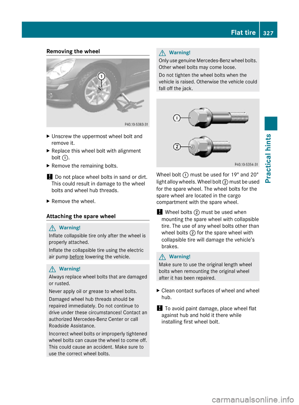
X
Unscrew the uppermost wheel bolt and
remove it.
X Replace this wheel bolt with alignment
bolt :.
X Remove the remaining bolts.
! Do not place wheel bolts in sand or dirt.
This could result in damage to the wheel
bolts and wheel hub threads.
X Remove the wheel.
Attaching the spare wheel G
Warning!
Inflate collapsible tire only after the wheel is
properly attached.
Inflate the collapsible tire using the electric
air pump before lowering the vehicle.
G
Warning!
Always replace wheel bolts that are damaged
or rusted.
Never apply oil or grease to wheel bolts.
Damaged wheel hub threads should be
repaired immediately. Do not continue to
drive under these circumstances! Contact an
authorized Mercedes-Benz Center or call
Roadside Assistance.
Incorrect wheel bolts or improperly tightened
wheel bolts can cause the wheel to come off.
This could cause an accident. Make sure to
use the correct wheel bolts. G
Warning!
Only use genuine Mercedes-Benz wheel bolts.
Other wheel bolts may come loose.
Do not tighten the wheel bolts when the
vehicle is raised. Otherwise the vehicle could
fall off the jack. Wheel bolt
: must be used for 19" and 20"
light alloy wheels. Wheel bolt ; must be used
for the spare wheel. The wheel bolts for the
spare wheel are located in the cargo
compartment with the spare wheel.
! Wheel bolts ; must be used when
mounting the spare wheel with collapsible
tire. The use of any wheel bolts other than
wheel bolts ; for the spare wheel with
collapsible tire will damage the vehicle’s
brakes. G
Warning!
Make sure to use the original length wheel
bolts when remounting the original wheel
after it has been repaired.
X Clean contact surfaces of wheel and wheel
hub.
! To avoid paint damage, place wheel flat
against hub and hold it there while
installing first wheel bolt. Flat tire
327Practical hints
251_AKB; 4; 52, en-US
d2ureepe, Version: 2.11.8.1 2009-03-23T09:22:52+01:00 - Seite 327 Z
Page 338 of 364
Only use a battery charge unit with a
maximum charging voltage of 14.8 V.
X
Charge battery in accordance with the
instructions of the battery charger
manufacturer. Jump starting
G
Warning!
Failure to follow these directions will cause
damage to the electronic components, and
can lead to a battery explosion and severe
injury or death.
Never
lean over batteries while connecting or
jump starting. You might get injured.
Battery fluid contains sulfuric acid. Do not
allow this fluid to come in contact with eyes,
skin or clothing. In case it does, immediately
flush affected area with water, and seek
medical help if necessary.
A battery will also produce hydrogen gas,
which is flammable and explosive. Keep
flames or sparks away from battery, avoid
improper connection of jumper cables,
smoking, etc.
Attempting to jump start a frozen battery can
result in it exploding, causing personal injury.
Read all instructions before proceeding.
! Do not tow-start the vehicle. You could
otherwise seriously damage the automatic
transmission which is not covered by the
Mercedes-Benz Limited Warranty.
! Jump starting should only be performed
using the jump-start terminals located in
the engine compartment.
Avoid repeated and lengthy starting
attempts.
Do not attempt to start the engine using a
battery quick-charge unit. If the engine does not run after several
unsuccessful starting attempts, have it
checked at the nearest authorized
Mercedes-Benz Center.
Excessive unburned fuel generated by
repeated failed starting attempts may
damage the catalytic converter
17
and may
present a fire risk.
Make sure the jumper cables do not have
loose or missing insulation.
Make sure the cable clamps do not touch
any
other metal part while the other end is
still attached to a battery.
If the battery is discharged, the engine can be
started with jumper cables and the fully
charged battery of another vehicle or an
equivalent starter pack. Observe the
following:
R Access to the battery is not possible on all
vehicles. If you cannot access the battery
of the other vehicle, provide jump start
power by an external battery or starter
pack.
R Jump starting should only be performed
when the engine and catalytic converter 18
are cold.
R Do not start the engine if the battery is
frozen. Let the battery thaw out first.
R Only jump start from batteries with the
same voltage rating (12 V). Jump starting
with a more powerful battery could damage
the vehicle’s electrical system. Such
damage will not be covered by the
Mercedes-Benz Limited Warranty.
R Only use jumper cables with sufficient
cross-section and insulated terminal
clamps.
R Always make sure the jumper cables are
not on or near pulleys, fans or other parts
17 Vehicles with gasoline engine only.
18 Vehicles with gasoline engine only. 336
Jump starting
Practical hints
251_AKB; 4; 52, en-US
d2ureepe,
Version: 2.11.8.1 2009-03-23T09:22:52+01:00 - Seite 336
Page 348 of 364
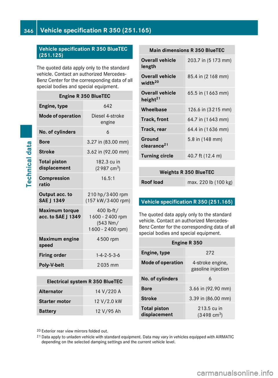
Vehicle specification R 350 BlueTEC
(251.125)
The quoted data apply only to the standard
vehicle. Contact an authorized Mercedes-
Benz
Center for the corresponding data of all
special bodies and special equipment. Engine R 350 BlueTEC
Engine, type
642
Mode of operation
Diesel 4-stroke
engine No. of cylinders
6
Bore
3.27 in (83.00 mm)
Stroke
3.62 in (92.00 mm)
Total piston
displacement
182.3 cu in
(2 987 cm 3
) Compression
ratio
16.5:1
Output acc. to
SAE J 1349
210 hp/3
400 rpm
(157 kW/3 400 rpm) Maximum torque
acc.
to SAE J 1349 400 lb-ft/
1 600 - 2 400 rpm
(543 Nm/
1 600 - 2 400 rpm) Maximum engine
speed
4 500 rpm
Firing order
1-4-2-5-3-6
Poly-V-belt
2 035 mm
Electrical system R 350 BlueTEC
Alternator
14 V/220 A
Starter motor
12 V/2.0 kW
Battery
12 V/95 Ah Main dimensions R 350 BlueTEC
Overall vehicle
length
203.7 in (5
173 mm) Overall vehicle
width
20 85.4 in (2
168 mm) Overall vehicle
height
21 65.5 in (1
663 mm) Wheelbase
126.6 in (3
215 mm) Track, front
64.7 in (1
643 mm) Track, rear
64.4 in (1
636 mm) Ground
clearance
21 5.8 in (148 mm)
Turning circle
40.7 ft (12.4 m)
Weights R 350 BlueTEC
Roof load
max. 220 lb (100 kg)
Vehicle specification R 350 (251.165)
The quoted data apply only to the standard
vehicle. Contact an authorized Mercedes-
Benz
Center for the corresponding data of all
special bodies and special equipment. Engine R 350
Engine, type
272
Mode of operation
4-stroke engine,
gasoline injection No. of cylinders
6
Bore
3.66 in (92.90 mm)
Stroke
3.39 in (86.00 mm)
Total piston
displacement
213.5 cu in
(3 498 cm 3
) 20
Exterior rear view mirrors folded out.
21 Data
apply to unladen vehicle with standard equipment. Data may vary in vehicles equipped with AIRMATIC
depending on the selected damping settings and the current vehicle level. 346
Vehicle specification R 350 (251.165)
Technical data
251_AKB; 4; 52, en-US
d2ureepe,
Version: 2.11.8.1 2009-03-23T09:22:52+01:00 - Seite 346