2010 MERCEDES-BENZ GL550 wheel
[x] Cancel search: wheelPage 166 of 380
ROff-road level 1, lower indicator lamp
flashes
ROff-road level 2, lower and middle
indicator lamps flashes
ROff-road level 3, lower, middle and upper
indicator lamps flashes
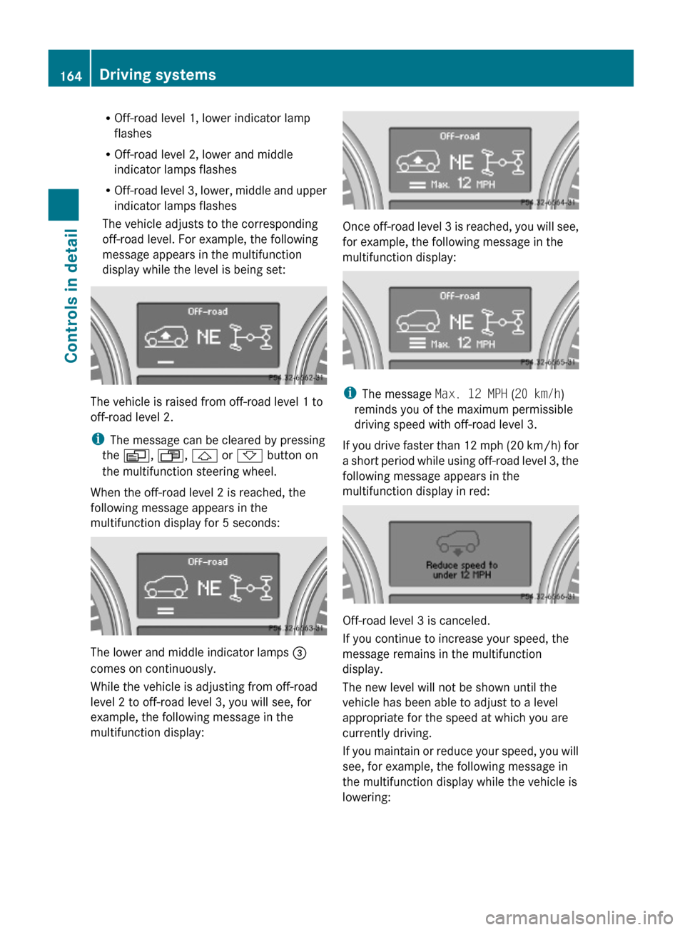
The vehicle adjusts to the corresponding
off-road level. For example, the following
message appears in the multifunction
display while the level is being set:
The vehicle is raised from off-road level 1 to
off-road level 2.
iThe message can be cleared by pressing
the V, U, & or * button on
the multifunction steering wheel.
When the off-road level 2 is reached, the
following message appears in the
multifunction display for 5 seconds:
The lower and middle indicator lamps =
comes on continuously.
While the vehicle is adjusting from off-road
level 2 to off-road level 3, you will see, for
example, the following message in the
multifunction display:
Once off-road level 3 is reached, you will see,
for example, the following message in the
multifunction display:
iThe message Max. 12 MPH (20 km/h)
reminds you of the maximum permissible
driving speed with off-road level 3.
If you drive faster than 12 mph (20 km/h) for
a short period while using off-road level 3, the
following message appears in the
multifunction display in red:
Off-road level 3 is canceled.
If you continue to increase your speed, the
message remains in the multifunction
display.
The new level will not be shown until the
vehicle has been able to adjust to a level
appropriate for the speed at which you are
currently driving.
If you maintain or reduce your speed, you will
see, for example, the following message in
the multifunction display while the vehicle is
lowering:
164Driving systemsControls in detail
X164_AKB; 5; 31, en-USd2ureepe,Version: 2.11.8.12009-09-11T12:30:16+02:00 - Seite 164
Page 168 of 380
iThe message can be cleared by pressing
the V, U, & or * button on
the multifunction steering wheel.
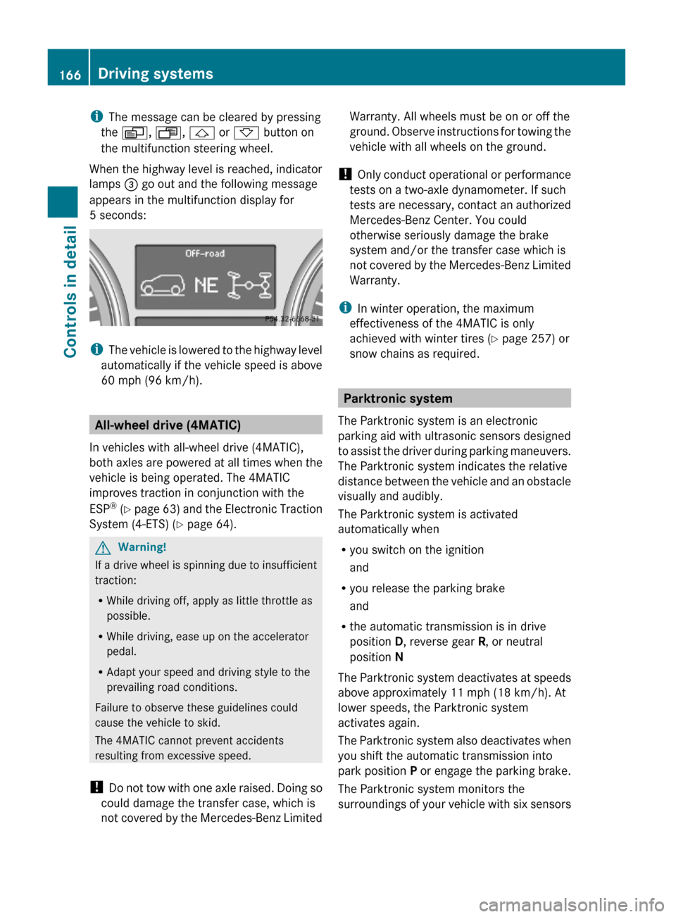
When the highway level is reached, indicator
lamps = go out and the following message
appears in the multifunction display for
5 seconds:
iThe vehicle is lowered to the highway level
automatically if the vehicle speed is above
60 mph (96 km/h).
All-wheel drive (4MATIC)
In vehicles with all-wheel drive (4MATIC),
both axles are powered at all times when the
vehicle is being operated. The 4MATIC
improves traction in conjunction with the
ESP® (Y page 63) and the Electronic Traction
System (4-ETS) (Y page 64).
GWarning!
If a drive wheel is spinning due to insufficient
traction:
RWhile driving off, apply as little throttle as
possible.
RWhile driving, ease up on the accelerator
pedal.
RAdapt your speed and driving style to the
prevailing road conditions.
Failure to observe these guidelines could
cause the vehicle to skid.
The 4MATIC cannot prevent accidents
resulting from excessive speed.
! Do not tow with one axle raised. Doing so
could damage the transfer case, which is
not covered by the Mercedes-Benz Limited
Warranty. All wheels must be on or off the
ground. Observe instructions for towing the
vehicle with all wheels on the ground.
! Only conduct operational or performance
tests on a two-axle dynamometer. If such
tests are necessary, contact an authorized
Mercedes-Benz Center. You could
otherwise seriously damage the brake
system and/or the transfer case which is
not covered by the Mercedes-Benz Limited
Warranty.
iIn winter operation, the maximum
effectiveness of the 4MATIC is only
achieved with winter tires (Y page 257) or
snow chains as required.
Parktronic system
The Parktronic system is an electronic
parking aid with ultrasonic sensors designed
to assist the driver during parking maneuvers.
The Parktronic system indicates the relative
distance between the vehicle and an obstacle
visually and audibly.
The Parktronic system is activated
automatically when
Ryou switch on the ignition
and
Ryou release the parking brake
and
Rthe automatic transmission is in drive
position D, reverse gear R, or neutral
position N
The Parktronic system deactivates at speeds
above approximately 11 mph (18 km/h). At
lower speeds, the Parktronic system
activates again.
The Parktronic system also deactivates when
you shift the automatic transmission into
park position P or engage the parking brake.
The Parktronic system monitors the
surroundings of your vehicle with six sensors
166Driving systemsControls in detail
X164_AKB; 5; 31, en-USd2ureepe,Version: 2.11.8.12009-09-11T12:30:16+02:00 - Seite 166
Page 175 of 380
For best possible performance of the climate
control:
XKeep the air intake grille in front of the
windshield free of snow, leaves, sticks, and
any other debris.
XAlways keep all air vents and grilles in the
passenger compartment free from
obstruction.
iFor draft-free ventilation, move the
adjustable center and side air vents to the
middle position.
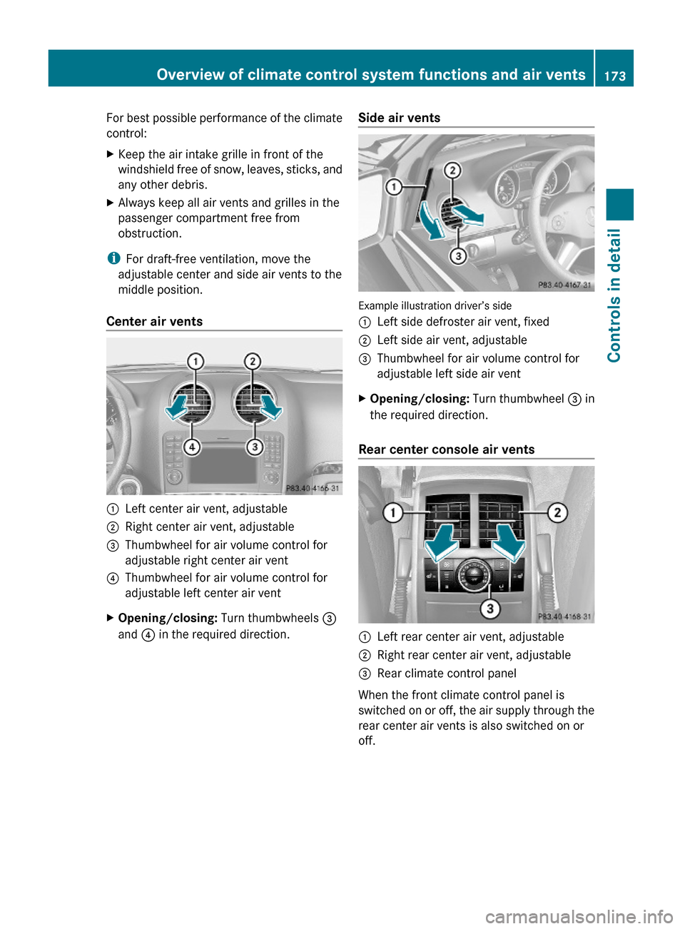
Center air vents
:Left center air vent, adjustable;Right center air vent, adjustable=Thumbwheel for air volume control for
adjustable right center air vent
?Thumbwheel for air volume control for
adjustable left center air vent
XOpening/closing: Turn thumbwheels =
and ? in the required direction.
Side air vents
Example illustration driver’s side
:Left side defroster air vent, fixed;Left side air vent, adjustable=Thumbwheel for air volume control for
adjustable left side air vent
XOpening/closing: Turn thumbwheel = in
the required direction.
Rear center console air vents
:Left rear center air vent, adjustable;Right rear center air vent, adjustable=Rear climate control panel
When the front climate control panel is
switched on or off, the air supply through the
rear center air vents is also switched on or
off.
Overview of climate control system functions and air vents173Controls in detailX164_AKB; 5; 31, en-USd2ureepe,Version: 2.11.8.12009-09-11T12:30:16+02:00 - Seite 173Z
Page 176 of 380
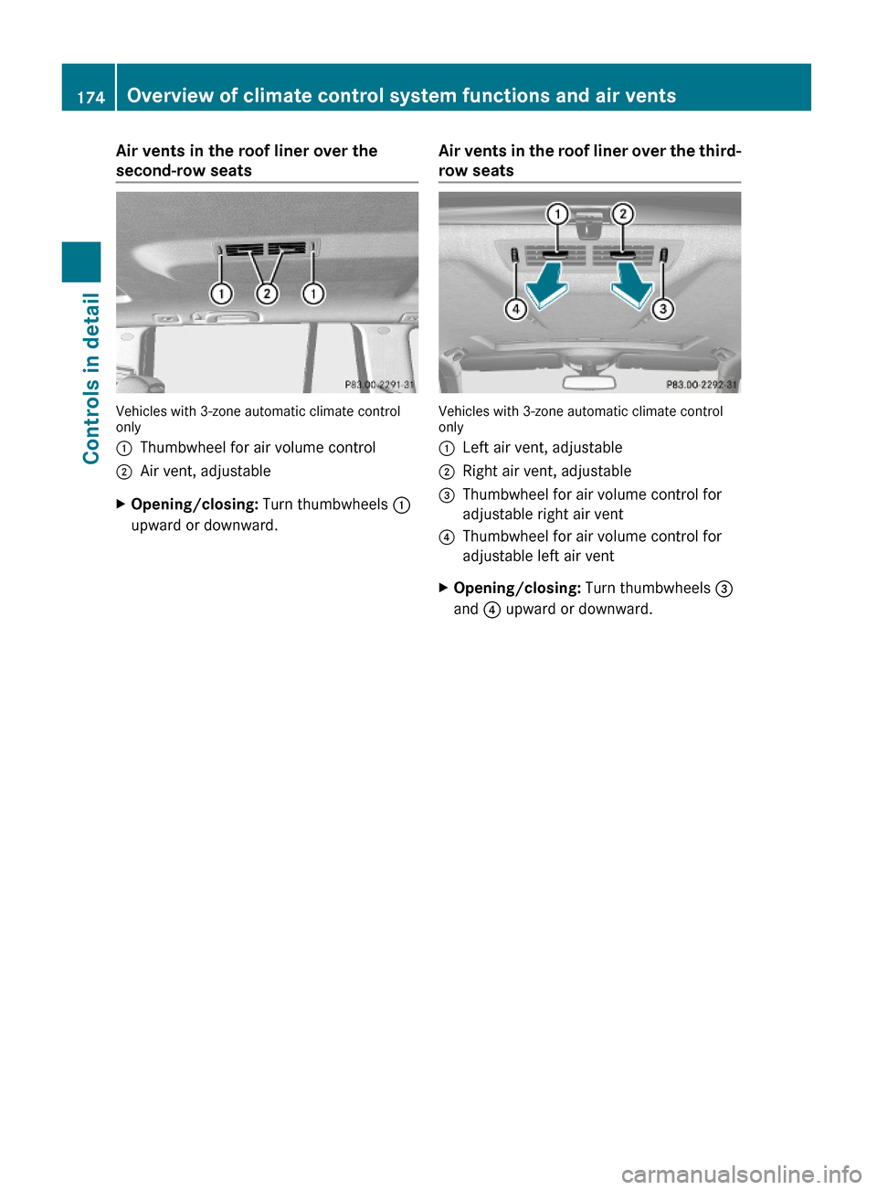
Air vents in the roof liner over the
second-row seats
Vehicles with 3-zone automatic climate controlonly
:Thumbwheel for air volume control;Air vent, adjustableXOpening/closing: Turn thumbwheels :
upward or downward.
Air vents in the roof liner over the third-
row seats
Vehicles with 3-zone automatic climate controlonly
:Left air vent, adjustable;Right air vent, adjustable=Thumbwheel for air volume control for
adjustable right air vent
?Thumbwheel for air volume control for
adjustable left air vent
XOpening/closing: Turn thumbwheels =
and ? upward or downward.
174Overview of climate control system functions and air ventsControls in detail
X164_AKB; 5; 31, en-USd2ureepe,Version: 2.11.8.12009-09-11T12:30:16+02:00 - Seite 174
Page 197 of 380
The cargo compartment is the preferred place
to carry objects. Always use cargo tie-down
rings, and if so equipped, always use the cargo
net when transporting cargo.
Never drive a vehicle with the tailgate open.
Deadly carbon monoxide (CO) gases may
enter vehicle interior resulting in
unconsciousness and death.
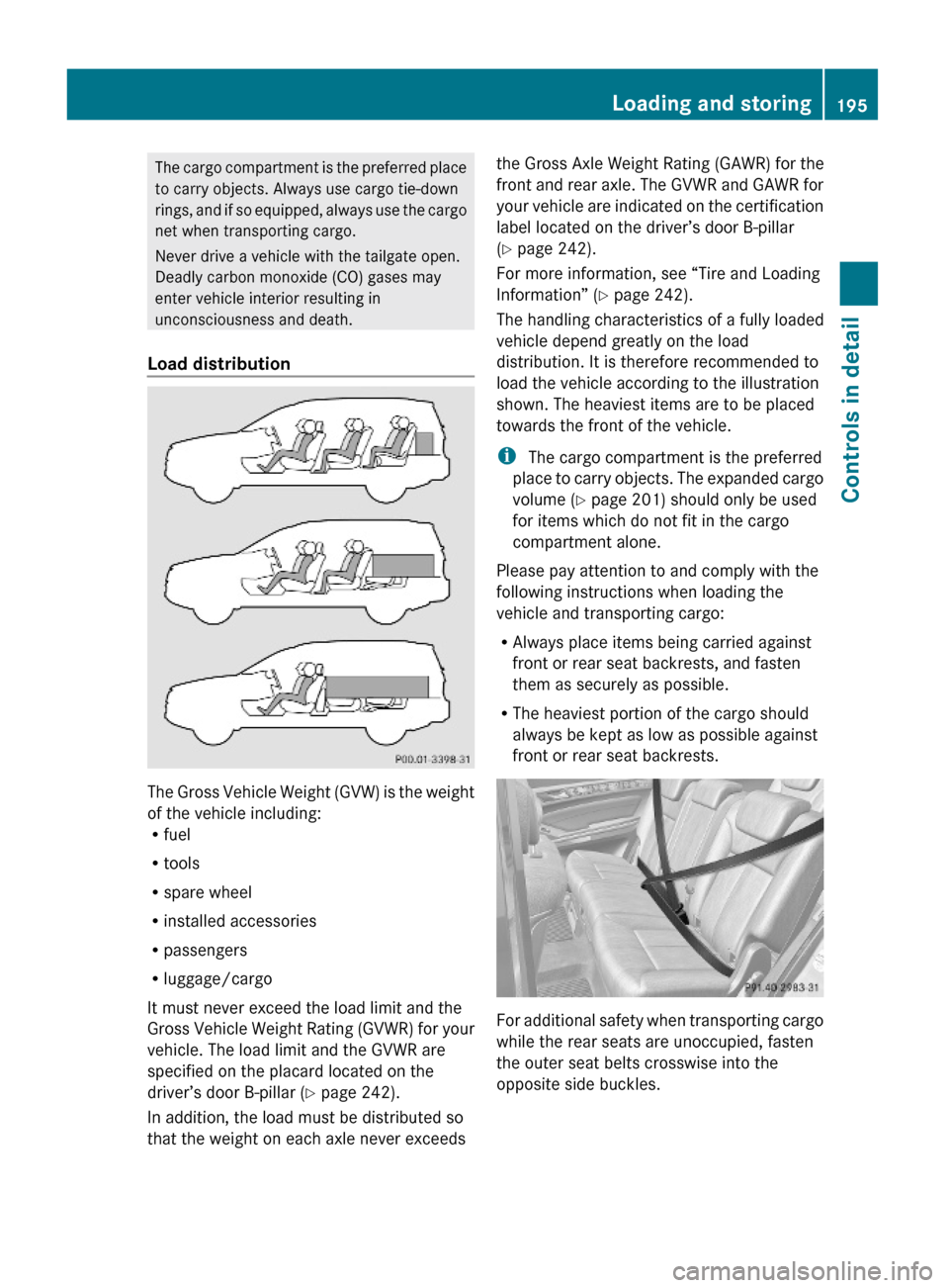
Load distribution
The Gross Vehicle Weight (GVW) is the weight
of the vehicle including:Rfuel
Rtools
Rspare wheel
Rinstalled accessories
Rpassengers
Rluggage/cargo
It must never exceed the load limit and the
Gross Vehicle Weight Rating (GVWR) for your
vehicle. The load limit and the GVWR are
specified on the placard located on the
driver’s door B-pillar (Y page 242).
In addition, the load must be distributed so
that the weight on each axle never exceeds
the Gross Axle Weight Rating (GAWR) for the
front and rear axle. The GVWR and GAWR for
your vehicle are indicated on the certification
label located on the driver’s door B-pillar
(Y page 242).
For more information, see “Tire and Loading
Information” (Y page 242).
The handling characteristics of a fully loaded
vehicle depend greatly on the load
distribution. It is therefore recommended to
load the vehicle according to the illustration
shown. The heaviest items are to be placed
towards the front of the vehicle.
i The cargo compartment is the preferred
place to carry objects. The expanded cargo
volume (Y page 201) should only be used
for items which do not fit in the cargo
compartment alone.
Please pay attention to and comply with the
following instructions when loading the
vehicle and transporting cargo:
RAlways place items being carried against
front or rear seat backrests, and fasten
them as securely as possible.
RThe heaviest portion of the cargo should
always be kept as low as possible against
front or rear seat backrests.
For additional safety when transporting cargo
while the rear seats are unoccupied, fasten
the outer seat belts crosswise into the
opposite side buckles.
Loading and storing195Controls in detailX164_AKB; 5; 31, en-USd2ureepe,Version: 2.11.8.12009-09-11T12:30:16+02:00 - Seite 195Z
Page 217 of 380
The Tele Aid system consists of three types
of response:
R Automatic and manual emergency
R Roadside Assistance
R Information
To adjust the speaker volume during a Tele
Aid call do the following:XPress button W or X on the
multifunction steering wheel.
or
XUse the adjustment button on your
COMAND system.
Be sure to check “Owner’s Online” at
www.mbusa.com (USA only) for more
information and a description of all available
features.
System self-test
The system performs a self-test after you
have switched on the ignition.
GWarning!
A malfunction in the system has been
detected if any or all of the following
conditions occur:
R The indicator lamp in the SOS button does
not come on during the system self-test.
R The indicator lamp in Roadside Assistance
button º does not come on during the
system self-test.
R The indicator lamp in Information button
E does not come on during the system
self-test.
R The indicator lamp in the SOS button,
Roadside Assistance button º, or
Information button E remains
illuminated constantly in red after the
system self-test.
R The message Tele Aid Inoperative or
Tele Aid Not Activated appears in the
multifunction display after the system self-
test
If a malfunction is indicated as outlined above,
the system may not operate as expected. In
case of an emergency, help will have to be
summoned by other means.
Have the system checked at the nearest
Mercedes-Benz Center or contact the
Customer Assistance Center at
1-800-FOR-MERCedes (1-800-367-6372)
(USA only) or 1-888-923-8367 (Canada only)
as soon as possible.
Emergency calls
! In order to activate the Tele Aid system, a
subscriber agreement must be completed.
To ensure your system is activated and
operational, please press Information
button E to perform the acquaintance
call. Failure to complete either of these
steps may result in a system that is not
activated.
If you have any questions regarding
activation, please call the Customer
Assistance Center at
1-800-FOR-MERCedes (1-800-367-6372)
(USA only) or 1-888-923-8367 (Canada
only).
An emergency call is initiated automatically
following an accident in which the Emergency
Tensioning Devices (ETDs) or air bags have
deployed.
i An automatically initiated Tele Aid
emergency call cannot be canceled.
An emergency call can also be initiated
manually ( Y page 216).
Once the emergency call is in progress, the
indicator lamp in the SOS button will begin to
flash. The message Connecting Call
appears in the multifunction display and the
COMAND system is muted. When the
connection is established, the message
Call Connected appears in the
multifunction display.
All information relevant to the emergency,
such as the location of the vehicle
Useful features215Controls in detailX164_AKB; 5; 31, en-USd2ureepe,Version: 2.11.8.12009-09-11T12:30:16+02:00 - Seite 215Z
Page 218 of 380

(determined by the GPS satellite location
system), vehicle model, identification number
and color are generated.
A voice connection between the Customer
Assistance Center and the occupants of the
vehicle will be established automatically soon
after the emergency call has been initiated.
The Customer Assistance Center will attempt
to determine the nature of the emergency
more precisely, provided they can speak to
an occupant of the vehicle.
iIf no vehicle occupant responds, an
ambulance will be sent to the vehicle
immediately.
GWarning!
If the indicator lamp in the SOS button is
flashing continuously and there was no voice
connection to the Customer Assistance
Center established, then the Tele Aid system
could not initiate an emergency call (e.g. the
relevant cellular phone network is not
available).
The message Call Failed appears in the
multifunction display for approximately
10 seconds.
Should this occur, assistance must be
summoned by other means.
iThe “911” emergency call system is a
public service. Using it without due cause
is a criminal offense.
Initiating an emergency call manually
XBriefly press on cover : to open.XPress SOS button ; briefly.
The indicator lamp in SOS button ; will
flash until the emergency call is concluded.
XWait for a voice connection to the
Customer Assistance Center.
XClose cover : after the emergency call is
concluded.
GWarning!
If you feel at any way in jeopardy when in the
vehicle (e.g. smoke or fire in the vehicle,
vehicle in a dangerous road location), please
do not wait for voice contact after you have
pressed the emergency button. Carefully
leave the vehicle and move to a safe location.
The Customer Assistance Center will
automatically contact local emergency
officials with the vehicle’s approximate
location if they receive an automatic SOS
signal and cannot make voice contact with the
vehicle occupants.
XTerminating calls: Press button ~ on
the multifunction steering wheel.
or
XPress the respective button for ending a
telephone call on the COMAND system.
Roadside Assistance button
XOpen the front armrest storage
compartment (Y page 208).
216Useful featuresControls in detail
X164_AKB; 5; 31, en-USd2ureepe,Version: 2.11.8.12009-09-11T12:30:16+02:00 - Seite 216
Page 219 of 380
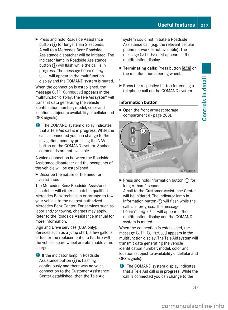
XPress and hold Roadside Assistance
button : for longer than 2 seconds.
A call to a Mercedes-Benz Roadside
Assistance dispatcher will be initiated. The
indicator lamp in Roadside Assistance
button : will flash while the call is in
progress. The message Connecting
Call will appear in the multifunction
display and the COMAND system is muted.
When the connection is established, the
message Call Connected appears in the
multifunction display. The Tele Aid system will
transmit data generating the vehicle
identification number, model, color and
location (subject to availability of cellular and
GPS signals).
i The COMAND system display indicates
that a Tele Aid call is in progress. While the
call is connected you can change to the
navigation menu by pressing the NAVI
button on the COMAND system. Spoken
commands are not available.
A voice connection between the Roadside
Assistance dispatcher and the occupants of
the vehicle will be established.
XDescribe the nature of the need for
assistance.
The Mercedes-Benz Roadside Assistance
dispatcher will either dispatch a qualified
Mercedes-Benz technician or arrange to tow
your vehicle to the nearest authorized
Mercedes-Benz Center. For services such as
labor and/or towing, charges may apply.
Refer to the Roadside Assistance manual for
more information.
Sign and Drive services (USA only):
Services such as a jump start, a few gallons
of fuel or the replacement of a flat tire with
the vehicle spare wheel are obtainable at no
charge.
iIf the indicator lamp in Roadside
Assistance button : is flashing
continuously and there was no voice
connection to the Customer Assistance
Center established, then the Tele Aid
system could not initiate a Roadside
Assistance call (e.g. the relevant cellular
phone network is not available). The
message Call Failed appears in the
multifunction display.
XTerminating calls: Press button ~ on
the multifunction steering wheel.
or
XPress the respective button for ending a
telephone call on the COMAND system.
Information button
XOpen the front armrest storage
compartment (Y page 208).
XPress and hold Information button : for
longer than 2 seconds.
A call to the Customer Assistance Center
will be initiated. The indicator lamp in
Information button : will flash while the
call is in progress. The message
Connecting Call will appear in the
multifunction display and the COMAND
system is muted.
When the connection is established, the
message Call Connected appears in the
multifunction display. The Tele Aid system will
transmit data generating the vehicle
identification number, model, color and
location (subject to availability of cellular and
GPS signals).
i The COMAND system display indicates
that a Tele Aid call is in progress. While the
call is connected you can change to the
Useful features217Controls in detailX164_AKB; 5; 31, en-USd2ureepe,Version: 2.11.8.12009-09-11T12:30:16+02:00 - Seite 217Z