2010 MERCEDES-BENZ GL450 ECU
[x] Cancel search: ECUPage 288 of 380
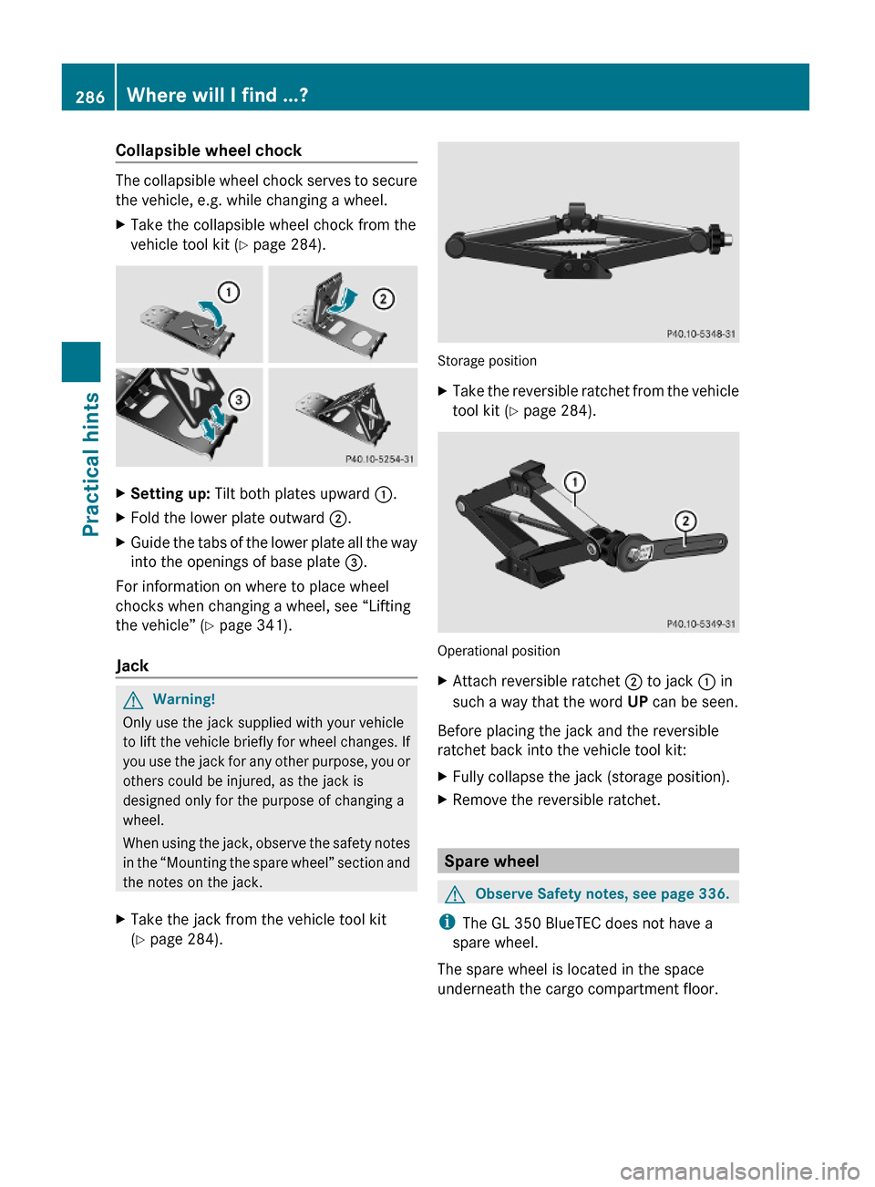
Collapsible wheel chock
The collapsible wheel chock serves to secure
the vehicle, e.g. while changing a wheel.
XTake the collapsible wheel chock from the
vehicle tool kit (Y page 284).
XSetting up: Tilt both plates upward :.XFold the lower plate outward ;.XGuide the tabs of the lower plate all the way
into the openings of base plate =.
For information on where to place wheel
chocks when changing a wheel, see “Lifting
the vehicle” (Y page 341).
Jack
GWarning!
Only use the jack supplied with your vehicle
to lift the vehicle briefly for wheel changes. If
you use the jack for any other purpose, you or
others could be injured, as the jack is
designed only for the purpose of changing a
wheel.
When using the jack, observe the safety notes
in the “Mounting the spare wheel” section and
the notes on the jack.
XTake the jack from the vehicle tool kit
(Y page 284).
Storage position
XTake the reversible ratchet from the vehicle
tool kit (Y page 284).
Operational position
XAttach reversible ratchet ; to jack : in
such a way that the word UP can be seen.
Before placing the jack and the reversible
ratchet back into the vehicle tool kit:
XFully collapse the jack (storage position).XRemove the reversible ratchet.
Spare wheel
GObserve Safety notes, see page 336.
iThe GL 350 BlueTEC does not have a
spare wheel.
The spare wheel is located in the space
underneath the cargo compartment floor.
286Where will I find ...?Practical hints
X164_AKB; 5; 31, en-USd2ureepe,Version: 2.11.8.12009-09-11T12:30:16+02:00 - Seite 286
Page 289 of 380
XRemoving: Open the tailgate (Y page 75).XLift the cargo compartment floor and
secure it on the upper cargo compartment
lip (Y page 284).
! To prevent damage, always disengage the
securing hook from upper cargo
compartment lip and lower the cargo
compartment floor before closing the
tailgate.
XRemove the jack from the vehicle tool kit
(Y page 285).
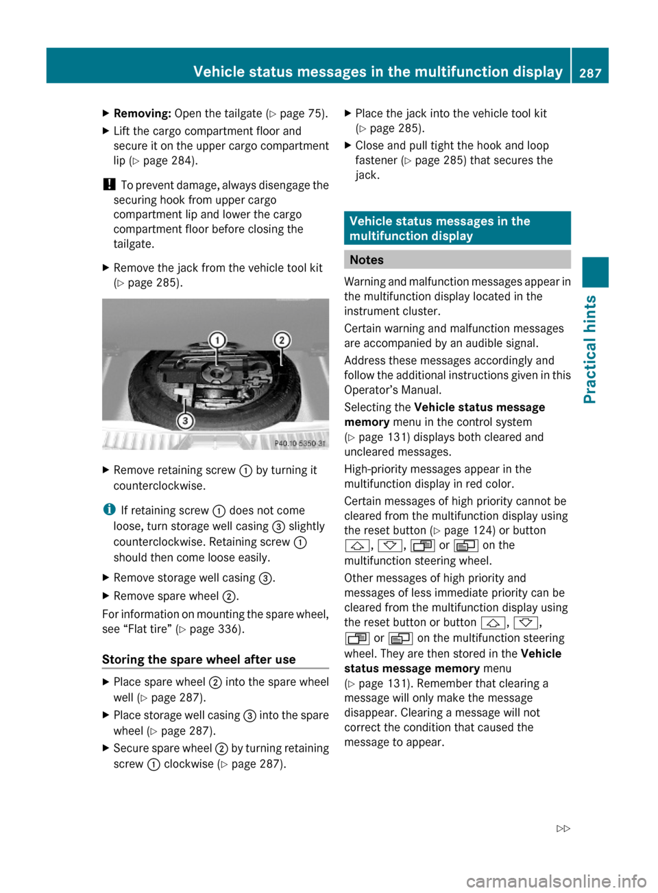
XRemove retaining screw : by turning it
counterclockwise.
iIf retaining screw : does not come
loose, turn storage well casing = slightly
counterclockwise. Retaining screw :
should then come loose easily.
XRemove storage well casing =.XRemove spare wheel ;.
For information on mounting the spare wheel,
see “Flat tire” (Y page 336).
Storing the spare wheel after use
XPlace spare wheel ; into the spare wheel
well (Y page 287).
XPlace storage well casing = into the spare
wheel (Y page 287).
XSecure spare wheel ; by turning retaining
screw : clockwise (Y page 287).
XPlace the jack into the vehicle tool kit
(Y page 285).
XClose and pull tight the hook and loop
fastener (Y page 285) that secures the
jack.
Vehicle status messages in the
multifunction display
Notes
Warning and malfunction messages appear in
the multifunction display located in the
instrument cluster.
Certain warning and malfunction messages
are accompanied by an audible signal.
Address these messages accordingly and
follow the additional instructions given in this
Operator’s Manual.
Selecting the Vehicle status message
memory menu in the control system
(Y page 131) displays both cleared and
uncleared messages.
High-priority messages appear in the
multifunction display in red color.
Certain messages of high priority cannot be
cleared from the multifunction display using
the reset button (Y page 124) or button
&, *, U or V on the
multifunction steering wheel.
Other messages of high priority and
messages of less immediate priority can be
cleared from the multifunction display using
the reset button or button &, *,
U or V on the multifunction steering
wheel. They are then stored in the Vehicle
status message memory menu
(Y page 131). Remember that clearing a
message will only make the message
disappear. Clearing a message will not
correct the condition that caused the
message to appear.
Vehicle status messages in the multifunction display287Practical hintsX164_AKB; 5; 31, en-USd2ureepe,Version: 2.11.8.12009-09-11T12:30:16+02:00 - Seite 287Z
Page 293 of 380
Display messagesPossible causes/consequences and M SolutionsFront
Passenger
Airbag
Enabled
See
Operator’s
ManualUSA only:
The front passenger front air bag is activated while driving
even though a child, small individual, or object below the
system’s weight threshold is on the front passenger seat, or
the front passenger seat is empty. Objects on the seat or
forces acting on the seat may make the system sense
supplemental weight.XStop the vehicle in a safe location as soon as possible.XEngage the parking brake.XSwitch off the ignition.XOpen the front passenger door.XRemove child and child restraint from front passenger seat
and properly secure the child in rear seat employing the
child restraint if necessary.XRemove any other items from on and around the front
passenger seat and make sure the parcel net on the back
of the front passenger seat is empty.XMake sure no objects which apply forces to the seat are
present (e.g. objects such as books, briefcases etc. lodged
behind or around the seat, head restraints pushing against
roof etc.). The system may recognize such forces as
supplemental weight and sense that an occupant on the
front passenger seat is of a greater weight than actually
present.XKeep the seat unoccupied, close the front passenger door
and switch on the ignition.
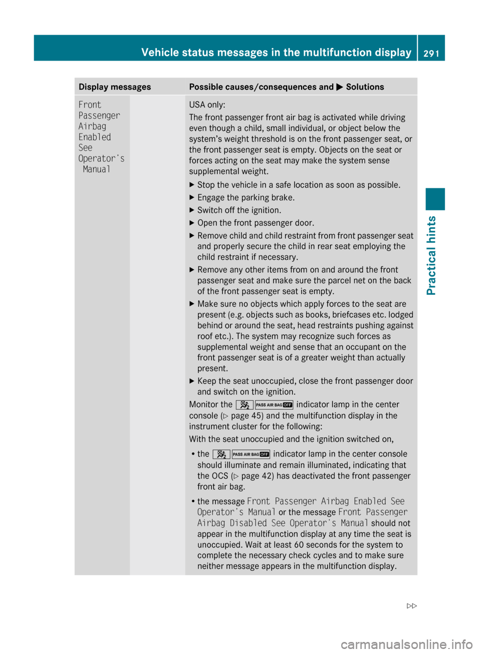
Monitor the 42 indicator lamp in the center
console ( Y page 45) and the multifunction display in the
instrument cluster for the following:
With the seat unoccupied and the ignition switched on,
R the 42 indicator lamp in the center console
should illuminate and remain illuminated, indicating that
the OCS ( Y page 42) has deactivated the front passenger
front air bag.
R the message Front Passenger Airbag Enabled See
Operator’s Manual or the message Front Passenger
Airbag Disabled See Operator’s Manual should not
appear in the multifunction display at any time the seat is
unoccupied. Wait at least 60 seconds for the system to
complete the necessary check cycles and to make sure
neither message appears in the multifunction display.
Vehicle status messages in the multifunction display291Practical hintsX164_AKB; 5; 31, en-USd2ureepe,Version: 2.11.8.12009-09-11T12:30:16+02:00 - Seite 291Z
Page 337 of 380
Removing wiper blades
Front wiper blades
! Do not pull on the wiper blade inserts.
They could tear.
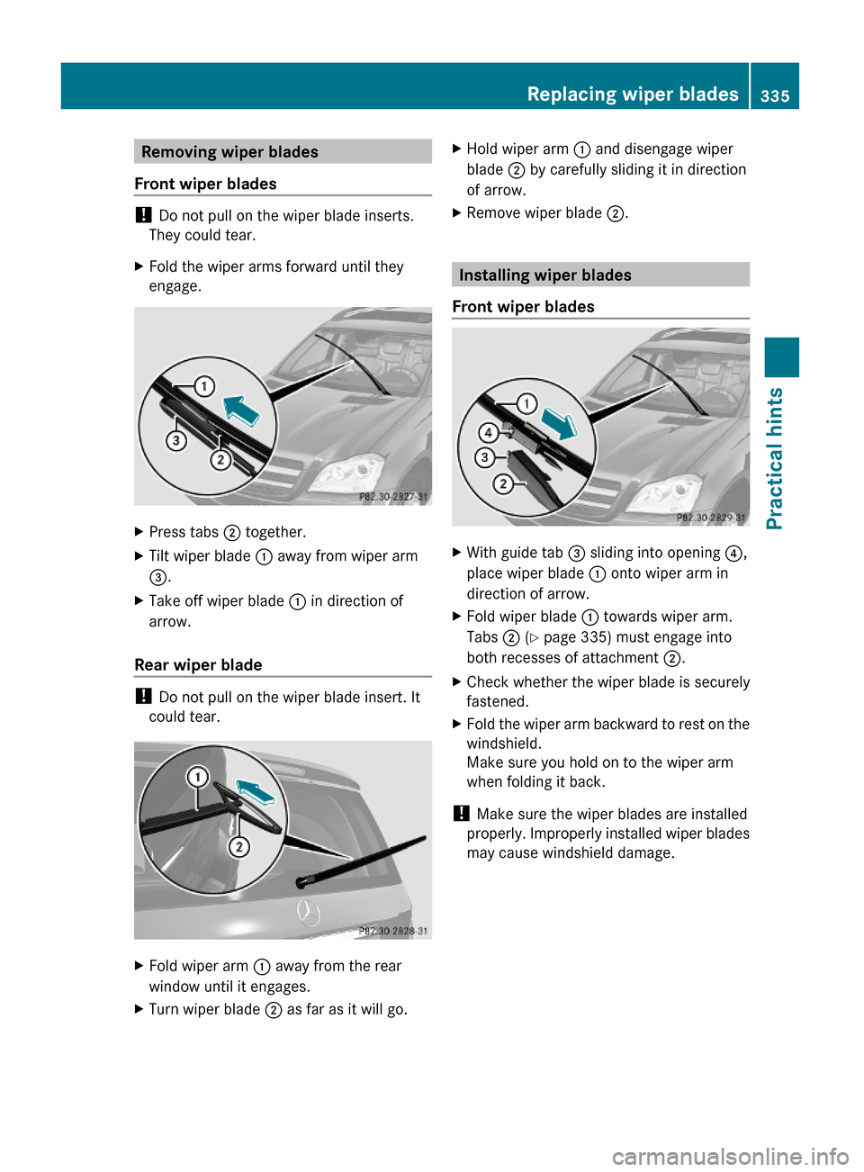
XFold the wiper arms forward until they
engage.
XPress tabs ; together.XTilt wiper blade : away from wiper arm
=.
XTake off wiper blade : in direction of
arrow.
Rear wiper blade
! Do not pull on the wiper blade insert. It
could tear.
XFold wiper arm : away from the rear
window until it engages.
XTurn wiper blade ; as far as it will go.XHold wiper arm : and disengage wiper
blade ; by carefully sliding it in direction
of arrow.
XRemove wiper blade ;.
Installing wiper blades
Front wiper blades
XWith guide tab = sliding into opening ?,
place wiper blade : onto wiper arm in
direction of arrow.
XFold wiper blade : towards wiper arm.
Tabs ; (Y page 335) must engage into
both recesses of attachment ;.
XCheck whether the wiper blade is securely
fastened.
XFold the wiper arm backward to rest on the
windshield.
Make sure you hold on to the wiper arm
when folding it back.
! Make sure the wiper blades are installed
properly. Improperly installed wiper blades
may cause windshield damage.
Replacing wiper blades335Practical hintsX164_AKB; 5; 31, en-USd2ureepe,Version: 2.11.8.12009-09-11T12:30:16+02:00 - Seite 335Z
Page 338 of 380
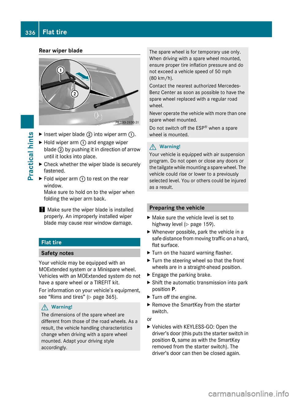
Rear wiper bladeXInsert wiper blade ; into wiper arm :.XHold wiper arm : and engage wiper
blade ; by pushing it in direction of arrow
until it locks into place.
XCheck whether the wiper blade is securely
fastened.
XFold wiper arm : to rest on the rear
window.
Make sure to hold on to the wiper when
folding the wiper arm back.
! Make sure the wiper blade is installed
properly. An improperly installed wiper
blade may cause rear window damage.
Flat tire
Safety notes
Your vehicle may be equipped with an
MOExtended system or a Minispare wheel.
Vehicles with an MOExtended system do not
have a spare wheel or a TIREFIT kit.
For information on your vehicle’s equipment,
see “Rims and tires” (Y page 365).
GWarning!
The dimensions of the spare wheel are
different from those of the road wheels. As a
result, the vehicle handling characteristics
change when driving with a spare wheel
mounted. Adapt your driving style
accordingly.
The spare wheel is for temporary use only.
When driving with a spare wheel mounted,
ensure proper tire inflation pressure and do
not exceed a vehicle speed of 50 mph
(80 km/h).
Contact the nearest authorized Mercedes-
Benz Center as soon as possible to have the
spare wheel replaced with a regular road
wheel.
Never operate the vehicle with more than one
spare wheel mounted.
Do not switch off the ESP® when a spare
wheel is mounted.
GWarning!
Your vehicle is equipped with air suspension
program. Do not open or close any doors or
the tailgate while mounting a spare wheel. The
vehicle could rise or lower to a previously
selected level. You or others could be injured
as a result.
Preparing the vehicle
XMake sure the vehicle level is set to
highway level (Y page 159).
XWhenever possible, park the vehicle in a
safe distance from moving traffic on a hard,
flat surface.
XTurn on the hazard warning flasher.XTurn the steering wheel so that the front
wheels are in a straight-ahead position.
XEngage the parking brake.XShift the automatic transmission into park
position P.
XTurn off the engine.XRemove the SmartKey from the starter
switch.
or
XVehicles with KEYLESS-GO: Open the
driver’s door (this puts the starter switch in
position 0, same as with the SmartKey
removed from the starter switch). The
driver’s door can then be closed again.
336Flat tirePractical hints
X164_AKB; 5; 31, en-USd2ureepe,Version: 2.11.8.12009-09-11T12:30:16+02:00 - Seite 336
Page 352 of 380
The factory-equipped battery may only be
replaced with a battery that
R has the same security features
R is of identical size
R is of identical voltage
R is of identical capacity
! As any other battery, the battery may
discharge if you do not operate the vehicle
for an extended period of time. Have the
battery disconnected at a qualified
workshop or an authorized Mercedes-Benz
Center in such a case. You may also
connect an accessory battery charge unit
expressly approved by Mercedes-Benz for
your vehicle model to maintain the battery
charge. Contact an authorized Mercedes-
Benz Center for further information.
The battery, the battery ventilation hose
and the lateral plug must always be
securely installed when the vehicle is in
operation.
! Never loosen or detach battery terminal
clamps while the engine is running or the
SmartKey is in the starter switch or
KEYLESS-GO button is in position 1.
Otherwise the alternator and other
electronic components could be severely
damaged.
Have the battery checked regularly at an
authorized Mercedes-Benz Center.
Refer to Maintenance Booklet for
maintenance intervals or contact an
authorized Mercedes-Benz Center for
further information.
i After battery power was interrupted, do
the following:
R Set the clock ( Y page 135).
Vehicles with COMAND system with
navigation module: Time and date are set
automatically.
R Synchronize the door windows
( Y page 107).R
Synchronize the power tilt/sliding
sunroof ( Y page 194).
R Synchronize the exterior rear view
mirrors ( Y page 96).
Charging the battery
GWarning!
Never charge a battery while still installed in
the vehicle unless the accessory battery
charge unit approved by Mercedes-Benz is
being used. Gases may escape during
charging and could cause an explosion that
may result in personal injury, paint damage or
corrosion.
An accessory battery charge unit specially
adapted for Mercedes-Benz vehicles and
tested and approved by Mercedes-Benz is
available. It permits the charging of the
battery in its installed position. Contact an
authorized Mercedes-Benz Center for
information and availability.
Charge battery in accordance with the
separate instructions for the accessory
battery charger.
Have the battery charged at an authorized
Mercedes-Benz Center. If you charge the
battery yourself, follow the operating
instructions for your charging device.
Only use a battery charge unit with a
maximum charging voltage of 14.8 V.
XCharge battery in accordance with the
instructions of the battery charger
manufacturer.
Jump starting
GWarning!
Failure to follow these directions will cause
damage to the electronic components, and
can lead to a battery explosion and severe
injury or death.
350Jump startingPractical hints
X164_AKB; 5; 31, en-USd2ureepe,Version: 2.11.8.12009-09-11T12:30:16+02:00 - Seite 350
Page 357 of 380
XMake sure the ignition is switched on.XWith the vehicle at a standstill, depress the
brake pedal and keep it pressed.XShift the automatic transmission into
neutral position N.XRelease the brake pedal.XIf engaged, release the parking brake.XSwitch on the hazard warning flasher
( Y page 101).
!
Keep in mind that it is important to have
the ignition switched on. Removing the
SmartKey from the starter switch or
opening a front door with the ignition
switched off will automatically shift the
automatic transmission into park position
P .
! The vehicle may be towed only for
distances up to 30 miles (50 km) and at a
speed not to exceed 30 mph (50 km/h).
i While being towed with the hazard
warning flasher in use, use the combination
switch in the usual manner to signal turns.
Only the selected turn signal will operate.
Upon canceling the turn signal, the hazard
warning flasher will operate again.
Stranded vehicle
Freeing a stranded vehicle, on which the
wheels are dug into sand or mud, should be
done with the greatest of care, especially if
the vehicle is heavily loaded.
Note the following when freeing a stranded
vehicle:
R Avoid pulling the vehicle abruptly or
diagonally, since it could result in damage
to the chassis alignment.
R Never try to free a vehicle that is still
coupled to a trailer.
R If possible, a vehicle equipped with a trailer
hitch receiver should be pulled backward in
its own previously made tracks.
Fuses
Introduction
The electrical fuses in your vehicle serve to
switch off malfunctioning power circuits.
If a fuse is blown, the components and
systems secured by that fuse will stop
operating.
GWarning!
Only use fuses approved by Mercedes-Benz
with the specified amperage for the system in
question and do not attempt to repair or
bridge a blown fuse. Using other than
approved fuses or using repaired or bridged
fuses may cause an overload leading to a fire,
and/or cause damage to electrical
components and/or systems. Have the cause
determined and remedied by an authorized
Mercedes-Benz Center.
A blown fuse must be replaced by an
appropriate spare fuse (recognizable by its
color or the fuse rating given on the fuse) of
the amperage recommended in the fuse
chart. Any Mercedes-Benz Center will be glad
to advise you on this subject.
i In case of a blown fuse contact Roadside
Assistance or an authorized Mercedes-
Benz Center.
If a newly inserted fuse blows again, have the
cause determined and rectified by an
authorized Mercedes-Benz Center.
The fuse chart is located in the cargo
compartment with the vehicle tool kit
( Y page 284). The fuse chart explains the fuse
allocation and fuse amperages.
Before replacing fuses
XEngage the parking brake.XMake sure the automatic transmission is in
park position P.
The transmission position indicator in the
multifunction display should be on P.XSwitch off all electrical consumers.Fuses355Practical hintsX164_AKB; 5; 31, en-USd2ureepe,Version: 2.11.8.12009-09-11T12:30:16+02:00 - Seite 355Z
Page 358 of 380

XTurn off the engine.XRemove the SmartKey from the starter
switch.
XVehicles with KEYLESS-GO: Open the
driver’s door (this puts the starter switch in
position 0, same as with the SmartKey
removed from the starter switch). The
driver’s door then can be closed again.
Fuse box in passenger compartment
! Do not use sharp objects such as a
screwdriver to open the fuse box cover in
the dashboard. You could damage the fuse
box cover or the dashboard.
The fuse box is located behind a cover in the
dashboard on the front passenger side.
XOpen the front passenger door.XOpening: Open the glove box.XOpening: Insert flat, blunt object as a lever
into the edge of fuse box cover : at the
position indicated by the arrow.
XLoosen fuse box cover : from the
dashboard using the lever.
XUsing your hands, pull fuse box cover :
out and remove.
XClosing: Hook fuse box cover : into
holders on the front of the dashboard.
XPress fuse box cover : back on until it
engages.
! The fuse box cover must be properly
positioned as described. Otherwise,
moisture or dirt could enter the fuse box
and possibly impair fuse operation.
Fuse box in engine compartment
XOpen the hood.
Example illustration fuse box GL 450 (GL 350BlueTEC, GL 550 similar)
XWith a dry cloth, remove any moisture from
fuse box cover :.
XOpening: Pull clamps ; in direction of
arrow.
XLift fuse box cover : up.XClosing: Make sure the sealing rubber is
positioned properly.
XPress fuse box cover : down and secure
with clamps ;.
! The fuse box cover must be properly
positioned as described. Otherwise,
moisture or dirt could enter the fuse box
and possibly impair fuse operation.
XClose the hood after checking or replacing
fuses.
356FusesPractical hints
X164_AKB; 5; 31, en-USd2ureepe,Version: 2.11.8.12009-09-11T12:30:16+02:00 - Seite 356