2010 JAGUAR XFR light
[x] Cancel search: lightPage 799 of 3039
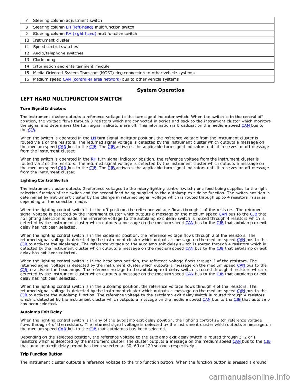
8 Steering column LH (left-hand) multifunction switch 9 Steering column RH (right-hand) multifunction switch 10 Instrument cluster 11 Speed control switches 12 Audio/telephone switches 13 Clockspring 14 Information and entertainment module 15 Media Oriented System Transport (MOST) ring connection to other vehicle systems 16 Medium speed CAN (controller area network) bus to other vehicle systems
LEFT HAND MULTIFUNCTION SWITCH
Turn Signal Indicators System Operation
The instrument cluster outputs a reference voltage to the turn signal indicator switch. When the switch is in the central off
position, the voltage flows through 3 resistors which are connected in series and back to the instrument cluster which monitors
the signal and determines the turn signal indicators are off. This information is broadcast on the medium speed CAN bus to the CJB.
When the switch is operated in the LH turn signal indicator position, the reference voltage from the instrument cluster is routed via 1 of the resistors. The returned signal voltage is detected by the instrument cluster which outputs a message on
the medium speed CAN bus to the CJB. The CJB activates the applicable turn signal indicators until it receives an off message from the instrument cluster.
When the switch is operated in the RH turn signal indicator position, the reference voltage from the instrument cluster is routed via 2 of the resistors. The returned signal voltage is detected by the instrument cluster which outputs a message on
the medium speed CAN bus to the CJB. The CJB activates the applicable turn signal indicators until it receives an off message from the instrument cluster.
Lighting Control Switch
The instrument cluster outputs 2 reference voltages to the rotary lighting control switch; one feed being supplied to the light
selection function of the switch and the second feed being supplied to the autolamp exit delay function. The switch position is
determined by instrument cluster by the change in returned signal voltage which is routed through up to 4 resistors in series
depending on the selection made.
When the lighting control switch is in the off position, the reference voltage flows through 1 of the resistors. The returned
signal voltage is detected by the instrument cluster which outputs a message on the medium speed CAN bus to the CJB that no lighting selection is made. The reference voltage to the autolamp exit delay switch is routed through 4 resistors which is
detected by the instrument cluster which outputs a message on the medium speed CAN bus to the CJB that autolamp or exit delay has not been selected.
When the lighting control switch is in the sidelamp position, the reference voltage flows through 2 of the resistors. The
returned signal voltage is detected by the instrument cluster which outputs a message on the medium speed CAN bus to the CJB to activate the sidelamps. The reference voltage to the autolamp exit delay switch is routed through 4 resistors which is detected by the instrument cluster which outputs a message on the medium speed CAN bus to the CJB that autolamp or exit delay has not been selected.
When the lighting control switch is in the headlamp position, the reference voltage flows through 3 of the resistors. The
returned signal voltage is detected by the instrument cluster which outputs a message on the medium speed CAN bus to the CJB to activate the headlamps. The reference voltage to the autolamp exit delay switch is routed through 4 resistors which is detected by the instrument cluster which outputs a message on the medium speed CAN bus to the CJB that autolamp or exit delay has not been selected.
When the lighting control switch is in the autolamp position, the reference voltage flows through 4 of the resistors. The
returned signal voltage is detected by the instrument cluster which outputs a message on the medium speed CAN bus to the CJB to activate the autolamp function. The reference voltage to the autolamp exit delay switch is routed through 4 resistors which is detected by the instrument cluster which outputs a message on the medium speed CAN bus to the CJB that autolamp has been selected.
Autolamp Exit Delay
When the lighting control switch is in any of the autolamp exit delay position, the lighting control switch reference voltage
flows through 4 of the resistors. The returned signal voltage is detected by the instrument cluster which outputs a message on
the medium speed CAN bus to the CJB that autolamps has been selected.
Depending on the selected position, the reference voltage to the autolamp exit delay switch is routed through 3, 2 or 1
resistors which is detected by the instrument cluster. The cluster outputs a message on the medium speed CAN bus to the CJB that autolamp exit delay period has been selected at 30, 60 or 120 seconds respectively.
Trip Function Button
The instrument cluster outputs a reference voltage to the trip function button. When the function button is pressed a ground
Page 801 of 3039

battery power supply to be passed via the slip ring assembly in the steering wheel to the heated steering wheel control
module. The steering wheel module supplies power to the steering wheel heater element and also monitors the temperature
via a NTC (negative temperature coefficient) temperature sensor incorporated into the heater element. The control module
varies the power supply to the element to maintain the steering wheel rim at the optimum temperature.
Component Description STEERING COLUMN MULTIFUNCTION SWITCHES
The steering column multifunction switches are situated on the steering column and consists of the wiper switch, the turn
signal indicator/lighting switch and the trip computer switch.
The steering column adjustment switch is located in the steering column lower shroud on the LH side. The switch is a 4 position 'joystick' which controls reach and rake adjustment.
Steering wheel mounted switches on the LH side of the driver's airbag, control the audio and telephone functions. Switches on the RH side of the driver's airbag, control the speed control functions. For additional information, refer to:
Audio System (415-01A Information and Entertainment System, Description and Operation), Speed Control (310-03A, Description and Operation),
Speed Control (310-03B, Description and Operation),
Speed Control (310-03C, Description and Operation).
Two transmission paddle switches are located at the rear of the steering wheel.
Refer to: External Controls (307-05, Description and Operation).
LH Multifunction Switch
Item Description 1 High beam 2 Lighting control rotary switch 3 RH turn signal indicator 4 Headlamp flash 5 LH turn signal indicator 6 Trip computer function button The LH multifunction switch controls the following windshield wiper functions:
Page 828 of 3039
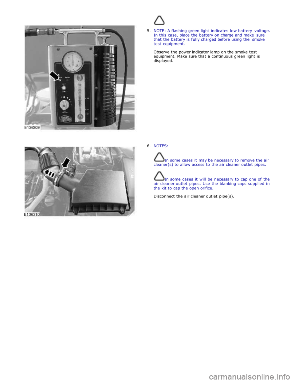
5. NOTE: A flashing green light indicates low battery voltage.
In this case, place the battery on charge and make sure
that the battery is fully charged before using the smoke
test equipment.
Observe the power indicator lamp on the smoke test
equipment. Make sure that a continuous green light is
displayed.
6. NOTES:
In some cases it may be necessary to remove the air
cleaner(s) to allow access to the air cleaner outlet pipes.
In some cases it will be necessary to cap one of the
air cleaner outlet pipes. Use the blanking caps supplied in
the kit to cap the open orifice.
Disconnect the air cleaner outlet pipe(s).
Page 829 of 3039
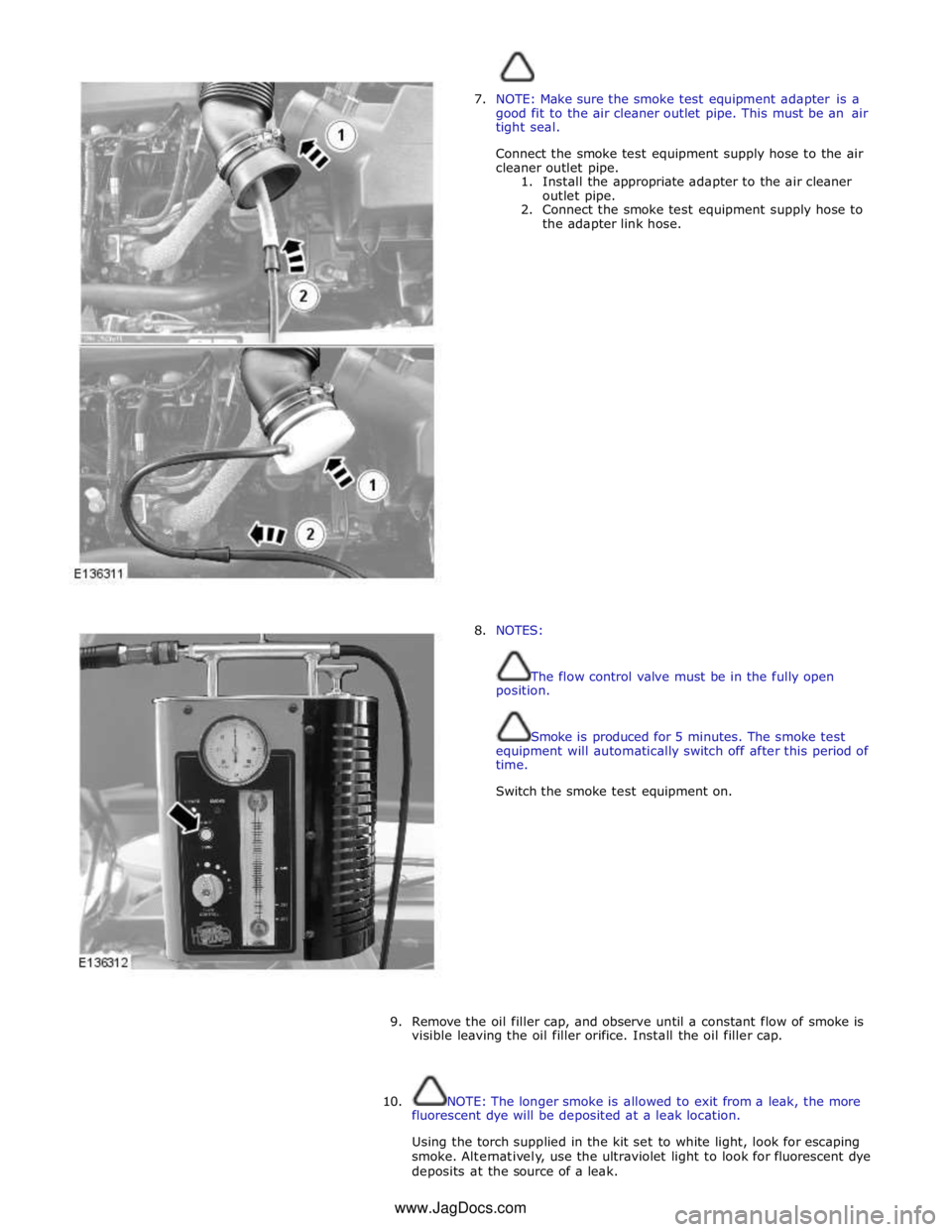
7. NOTE: Make sure the smoke test equipment adapter is a
good fit to the air cleaner outlet pipe. This must be an air
tight seal.
Connect the smoke test equipment supply hose to the air
cleaner outlet pipe.
1. Install the appropriate adapter to the air cleaner
outlet pipe.
2. Connect the smoke test equipment supply hose to
the adapter link hose.
8. NOTES:
The flow control valve must be in the fully open
position.
Smoke is produced for 5 minutes. The smoke test
equipment will automatically switch off after this period of
time.
Switch the smoke test equipment on.
9. Remove the oil filler cap, and observe until a constant flow of smoke is
visible leaving the oil filler orifice. Install the oil filler cap.
10. NOTE: The longer smoke is allowed to exit from a leak, the more
fluorescent dye will be deposited at a leak location.
Using the torch supplied in the kit set to white light, look for escaping
smoke. Alternatively, use the ultraviolet light to look for fluorescent dye
deposits at the source of a leak. www.JagDocs.com
Page 853 of 3039
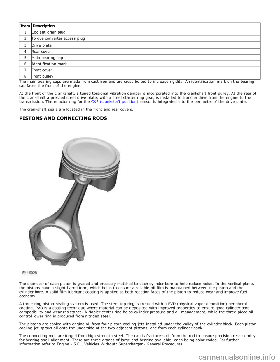
1 Coolant drain plug 2 Torque converter access plug 3 Drive plate 4 Rear cover 5 Main bearing cap 6 Identification mark 7 Front cover 8 Front pulley The main bearing caps are made from cast iron and are cross bolted to increase rigidity. An identification mark on the bearing
cap faces the front of the engine.
At the front of the crankshaft, a tuned torsional vibration damper is incorporated into the crankshaft front pulley. At the rear of
the crankshaft a pressed steel drive plate, with a steel starter ring gear, is installed to transfer drive from the engine to the
transmission. The reluctor ring for the CKP (crankshaft position) sensor is integrated into the perimeter of the drive plate.
The crankshaft seals are located in the front and rear covers.
PISTONS AND CONNECTING RODS
The diameter of each piston is graded and precisely matched to each cylinder bore to help reduce noise. In the vertical plane,
the pistons have a slight barrel form, which helps to ensure a reliable oil film is maintained between the piston and the
cylinder bore. A solid film lubricant coating is applied to both reaction faces of the piston to reduce wear and improve fuel
economy.
A three-ring piston-sealing system is used. The steel top ring is treated with a PVD (physical vapor deposition) peripheral
coating. PVD is a coating technique where material can be deposited with improved properties to ensure good cylinder bore
compatibility and wear resistance. A Napier center ring helps cylinder pressure and oil management, while the three-piece oil
control lower ring is produced from nitrided steel.
The pistons are cooled with engine oil from four piston cooling jets installed under the valley of the cylinder block. Each piston
cooling jet sprays oil onto the underside of the two adjacent pistons, one from each cylinder bank.
The connecting rods are forged from high strength steel. The cap is fracture-split from the rod to ensure precision re-assembly
for bearing shell alignment. There are three grades of large end bearing available, each being color coded. For further
information refer to Engine - 5.0L, Vehicles Without: Supercharger - General Procedures.
Page 858 of 3039
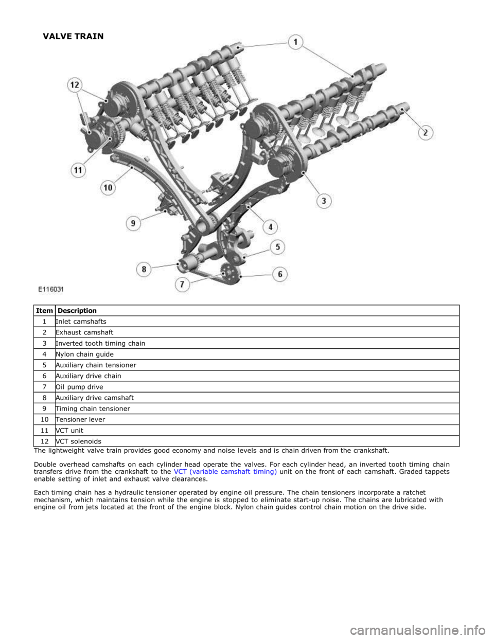
1 Inlet camshafts 2 Exhaust camshaft 3 Inverted tooth timing chain 4 Nylon chain guide 5 Auxiliary chain tensioner 6 Auxiliary drive chain 7 Oil pump drive 8 Auxiliary drive camshaft 9 Timing chain tensioner 10 Tensioner lever 11 VCT unit 12 VCT solenoids The lightweight valve train provides good economy and noise levels and is chain driven from the crankshaft.
Double overhead camshafts on each cylinder head operate the valves. For each cylinder head, an inverted tooth timing chain
transfers drive from the crankshaft to the VCT (variable camshaft timing) unit on the front of each camshaft. Graded tappets
enable setting of inlet and exhaust valve clearances.
Each timing chain has a hydraulic tensioner operated by engine oil pressure. The chain tensioners incorporate a ratchet
mechanism, which maintains tension while the engine is stopped to eliminate start-up noise. The chains are lubricated with
engine oil from jets located at the front of the engine block. Nylon chain guides control chain motion on the drive side. VALVE TRAIN
Page 1086 of 3039
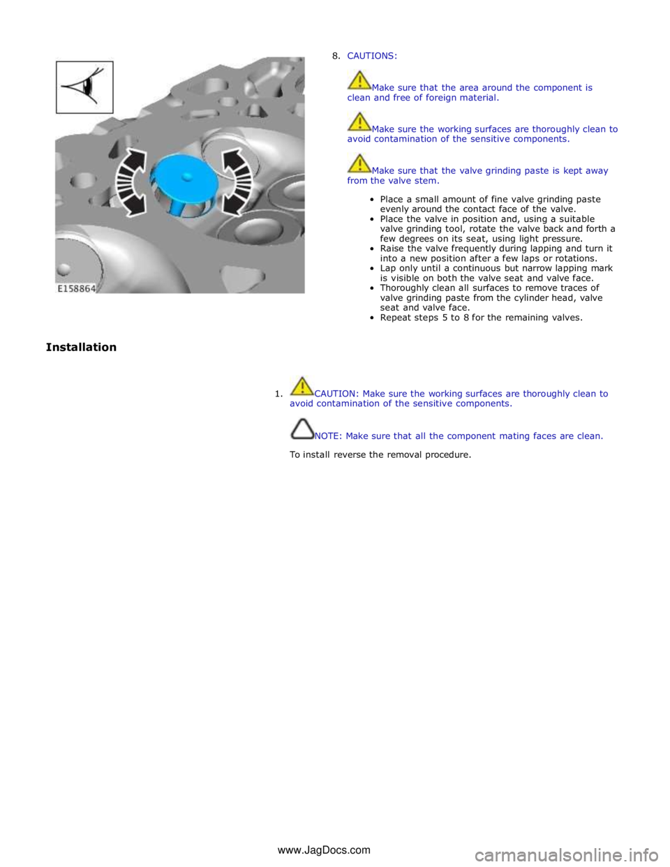
8. CAUTIONS:
Make sure that the area around the component is
clean and free of foreign material.
Make sure the working surfaces are thoroughly clean to
avoid contamination of the sensitive components.
Make sure that the valve grinding paste is kept away
from the valve stem.
Place a small amount of fine valve grinding paste
evenly around the contact face of the valve.
Place the valve in position and, using a suitable
valve grinding tool, rotate the valve back and forth a
few degrees on its seat, using light pressure.
Raise the valve frequently during lapping and turn it
into a new position after a few laps or rotations.
Lap only until a continuous but narrow lapping mark
is visible on both the valve seat and valve face.
Thoroughly clean all surfaces to remove traces of
valve grinding paste from the cylinder head, valve
seat and valve face.
Repeat steps 5 to 8 for the remaining valves.
Installation
1. CAUTION: Make sure the working surfaces are thoroughly clean to
avoid contamination of the sensitive components.
NOTE: Make sure that all the component mating faces are clean.
To install reverse the removal procedure. www.JagDocs.com
Page 1177 of 3039
Fuel Charging and Controls - V8 S/C 5.0L Petrol -
WARNINGS: Published: 11-May-2011
Do not smoke or carry lighted tobacco or open flame of any type when working on or near any fuel related components.
Highly flammable vapors are always present and may ignite. Failure to follow these instructions may result in personal injury.
Before any work is carried out on the fuel system, ground the vehicle to earth and maintain the ground connection until
the work is complete.
CAUTION: Before disconnecting or removing components, make sure the area around the joint faces and connections are
clean. Plug open connections to prevent contamination.
NOTE: Tighten the fuel rail high pressure fuel pump fuel line unions and fuel rail crossover pipe unions as it is instructed
in service manual.
Description Nm lb-ft lb-in Ignition coil-on-plugs retaining bolts 7 - 62 Spark plugs 20 15 - Fuel rail retaining bolt Stage 1 - 20 Stage 2 - 30 Stage 1 - 15 Stage 2 - 22 - Fuel rail crossover pipe unions 21 15 - Fuel rail crossover pipe retaining bolts 12 9 - Fuel pressure regulator 33 24 - Fuel rail high pressure fuel pump fuel line unions 21 15 - Fuel rail high pressure fuel pump fuel line M8 bolt 25 18 - Fuel rail high pressure fuel pump fuel line M6 bolt 11 8 - Fuel rail high pressure fuel pump fuel line M5 nut 6 - 53 Fuel rail high pressure fuel pump fuel line shield M10 bolt 29 21 - Fuel rail high-pressure fuel pump fuel line shield M6 bolt 11 8 - Fuel rail high pressure fuel pump torx bolts 12 9 - Throttle body retaining bolts 10 7 - Accessory drive belt idler pulley retaining bolts 25 18 - Steering gear retaining bolts 100 74 - Steering column lower universal joint assembly bolts 35 26 - Coolant expansion tank retaining bolt 10 7 - Engine compartment brace retaining bolts 45 33 - www.JagDocs.com