2010 JAGUAR XFR Module
[x] Cancel search: ModulePage 1836 of 3039
Warning Devices - Warning Devices
Diagnosis and Testing
Principles of Operation Published: 29-Apr-2013
For a detailed description of the Blindspot Monitoring system, refer to the relevant Description and Operation sections in the
workshop manual. REFER to: (413-09 Warning Devices)
Blindspot Monitoring System (Description and Operation), Blindspot Monitoring System (Description and Operation), Blindspot Monitoring System (Description and Operation).
Inspection and Verification
CAUTION: Diagnosis by substitution from a donor vehicle is NOT acceptable. Substitution of control modules does not
guarantee confirmation of a fault, and may also cause additional faults in the vehicle being tested and/or the donor vehicle.
1. Verify the customer concern.
2. Visually inspect for obvious signs of damage and system integrity.
NOTE: Particular attention should be paid to the following items where DTCs may not be logged:
Check for contamination (e.g. dirt, grime, frosting, ice) around the blindspot monitoring sensors and clear.
Visual Inspection
Mechanical Electrical
Exterior rear view mirror glass
Mud or sleet contamination around rear bumper area
Blindspot Monitoring Modules
Fuse(s)
Relay(s)
Wiring Harness
Electrical connector(s)
Blindspot Monitoring Modules
3. If an obvious cause for an observed or reported concern is found, correct the cause (if possible) before proceeding to
the next step.
4. If the cause is not visually evident, verify the symptom and refer to the Symptom Chart, alternatively, check for
Diagnostic Trouble Codes (DTCs) and refer to the DTC Index.
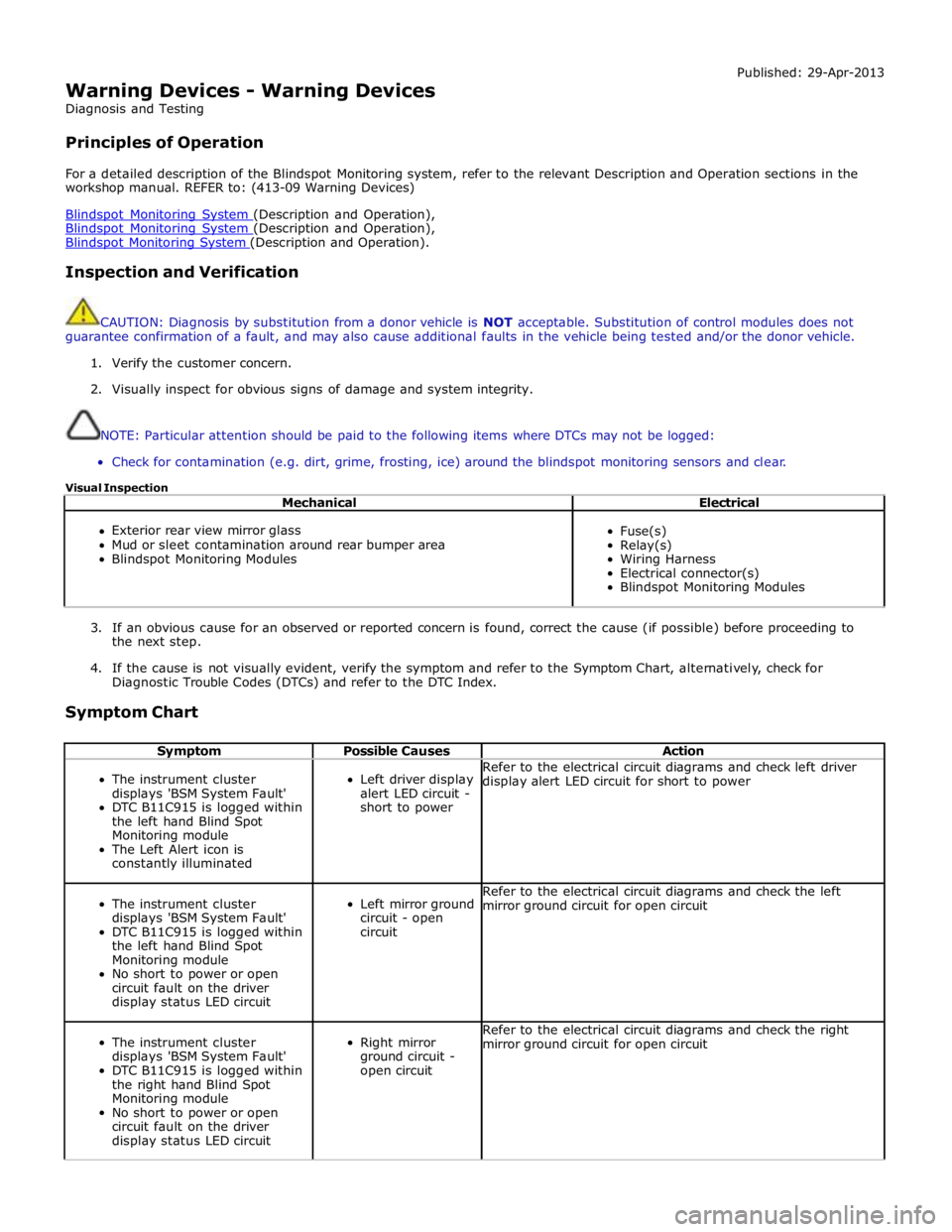
Symptom Chart
Symptom Possible Causes Action
The instrument cluster
displays 'BSM System Fault'
DTC B11C915 is logged within
the left hand Blind Spot
Monitoring module
The Left Alert icon is
constantly illuminated
Left driver display
alert LED circuit -
short to power Refer to the electrical circuit diagrams and check left driver
display alert LED circuit for short to power
The instrument cluster
displays 'BSM System Fault'
DTC B11C915 is logged within
the left hand Blind Spot
Monitoring module
No short to power or open
circuit fault on the driver
display status LED circuit
Left mirror ground
circuit - open
circuit Refer to the electrical circuit diagrams and check the left
mirror ground circuit for open circuit
The instrument cluster
displays 'BSM System Fault'
DTC B11C915 is logged within
the right hand Blind Spot
Monitoring module
No short to power or open
circuit fault on the driver
display status LED circuit
Right mirror
ground circuit -
open circuit Refer to the electrical circuit diagrams and check the right
mirror ground circuit for open circuit
Page 1837 of 3039

Symptom Possible Causes Action
The instrument cluster
displays 'BSM System Fault'
DTC U023200 is logged within
the right hand Blind Spot
Monitoring module
The left driver display status
LED does not illuminate when
the vehicle is stationary, in
Park and the ignition is on
Left driver display
status LED circuit
- short to ground
Harness fault
between left side
mirror and left
side module
Suspect left hand
module failure
Refer to the electrical circuit diagrams and check left
driver display status LED circuit for short to ground.
Clear DTC and re-test. If DTC remains suspect the left
hand Blindspot Monitoring module
Refer to the electrical circuit diagrams and check the
left side harness between the left side mirror and left
hand module
Check and install a new left hand Blindspot Monitoring
module only, refer to the new module/component
installation note at the top of the DTC Index
The instrument cluster
displays 'BSM System Fault'
DTC U023200 is logged within
the right hand Blind Spot
Monitoring module
When the system is powered
up the left driver display alert
LED does not illuminate during
the bulb self-checks
Left driver display
alert LED - short
to ground, open
circuit
Harness fault
between left side
mirror and left
side module
Suspect left hand
module failure
Refer to the electrical circuit diagrams and check left
driver display alert LED circuit for short to ground,
open circuit. Clear DTC and re-test. If DTC remains
suspect the left hand Blindspot Monitoring module
Refer to the electrical circuit diagrams and check the
left side harness between the left side mirror and left
hand module
Check and install a new left hand Blindspot Monitoring
module only, refer to the new module/component
installation note at the top of the DTC Index
The instrument cluster
displays 'BSM System Fault'
DTC U023300 is logged within
the left hand Blind Spot
Monitoring module
The right driver display status
LED is constantly illuminated
Right driver
display status LED
- short to power
Harness fault
between right side
mirror and right
side module
Suspect right hand
module failure
Refer to the electrical circuit diagrams and check right
driver display status LED circuit for short to power.
Clear DTC and re-test. If DTC remains suspect the
right hand Blindspot Monitoring module
Refer to the electrical circuit diagrams and check the
right side harness between the right side mirror and
right hand module
Check and install a new right hand Blindspot
Monitoring module only, refer to the new
module/component installation note at the top of the
DTC Index
The instrument cluster
displays 'BSM System Fault'
DTC U023300 is logged within
the left hand Blind Spot
Monitoring module
When the system is powered
up the right driver display
status LED does not illuminate
during the bulb self-checks
Right driver
display status LED
- open circuit
Harness fault
between right side
mirror and right
side module
Suspect right hand
module failure
Refer to the electrical circuit diagrams and check right
driver display status LED circuit for open circuit. Clear
DTC and re-test. If DTC remains suspect the right
hand Blindspot Monitoring module
Refer to the electrical circuit diagrams and check the
right side harness between the right side mirror and
right hand module
Check and install a new right hand Blindspot
Monitoring module only, refer to the new
module/component installation note at the top of the
DTC Index
The instrument cluster
displays 'BSM System Fault'
DTC U023300 is logged within
the left hand Blind Spot
Monitoring module
When the system is powered
up both the right driver display
LEDs do not illuminate during
the bulb self-checks
Right mirror
ground circuit -
open circuit
Harness fault
between right side
mirror and right
side module
Suspect right hand
module failure
Refer to the electrical circuit diagrams and check the
right mirror ground circuit for open circuit. Clear DTC
and re-test. If DTC remains suspect the left hand
Blindspot Monitoring module
Refer to the electrical circuit diagrams and check the
right side harness between the right side mirror and
right hand module
Check and install a new right hand Blindspot
Monitoring module only, refer to the new
module/component installation note at the top of the
DTC Index DTC Index
CAUTION: When probing connectors to take measurements in the course of the pinpoint tests, use the adaptor kit, part
number 3548-1358-00.
NOTES:
If the control module or a component is suspect and the vehicle remains under manufacturer warranty, refer to the
Warranty Policy and Procedures manual (section B1.2), or determine if any prior approval programme is in operation, prior to
the installation of a new module/component.
www.JagDocs.com
Page 1838 of 3039
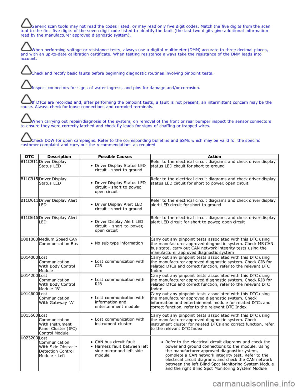
Generic scan tools may not read the codes listed, or may read only five digit codes. Match the five digits from the scan
tool to the first five digits of the seven digit code listed to identify the fault (the last two digits give additional information
read by the manufacturer approved diagnostic system).
When performing voltage or resistance tests, always use a digital multimeter (DMM) accurate to three decimal places,
and with an up-to-date calibration certificate. When testing resistance always take the resistance of the DMM leads into
account.
Check and rectify basic faults before beginning diagnostic routines involving pinpoint tests.
Inspect connectors for signs of water ingress, and pins for damage and/or corrosion.
If DTCs are recorded and, after performing the pinpoint tests, a fault is not present, an intermittent concern may be the
cause. Always check for loose connections and corroded terminals.
When carrying out repair/diagnosis of the system, on removal of the front or rear bumper inspect the sensor connectors
to ensure they were correctly latched and check fly leads for signs of chaffing or trapped wires.
Check DDW for open campaigns. Refer to the corresponding bulletins and SSMs which may be valid for the specific
customer complaint and carry out the recommendations as required
DTC Description Possible Causes Action B11C911
Driver Display
Status LED
Driver Display Status LED
circuit - short to ground Refer to the electrical circuit diagrams and check driver display
status LED circuit for short to ground B11C915
Driver Display
Status LED
Driver Display Status LED
circuit - short to power,
open circuit Refer to the electrical circuit diagrams and check driver display
status LED circuit for short to power, open circuit B11D611
Driver Display Alert
LED
Driver Display Alert LED
circuit - short to ground Refer to the electrical circuit diagrams and check driver display
alert LED circuit for short to ground B11D615
Driver Display Alert
LED
Driver Display Alert LED
circuit - short to power,
open circuit Refer to the electrical circuit diagrams and check driver display
alert LED circuit for short to power, open circuit U001000
Medium Speed CAN
Communication Bus
No sub type information Carry out any pinpoint tests associated with this DTC using
the manufacturer approved diagnostic system. Check MS CAN
bus state, carry out CAN network integrity tests using the
manufacturer approved diagnostic system U014000
Lost
Communication
With Body Control
Module
Lost communication with
CJB Carry out any pinpoint tests associated with this DTC using
the manufacturer approved diagnostic system. Check CJB for
related DTCs and correct function, refer to the relevant DTC
Index U014200
Lost
Communication
With Body Control
Module "B"
Lost communication with
RJB Carry out any pinpoint tests associated with this DTC using
the manufacturer approved diagnostic system. Check RJB for
related DTCs and correct function, refer to the relevant DTC
Index U014600
Lost
Communication
With Gateway "A"
Lost communication with
information and
entertainment module Carry out any pinpoint tests associated with this DTC using
the manufacturer approved diagnostic system. Check
information and entertainment module for related DTCs and
correct function, refer to the relevant DTC Index U015500
Lost
Communication
With Instrument
Panel Cluster (IPC)
Control Module
Lost communication with
instrument cluster Carry out any pinpoint tests associated with this DTC using
the manufacturer approved diagnostic system. Check
instrument cluster for related DTCs and correct function, refer
to the relevant DTC Index U023200
Lost
Communication
With Side Obstacle
Detection Control
Module - Left
CAN bus circuit fault
Harness fault between left
side mirror and left side
module
Refer to the electrical circuit diagrams and check the
power and ground connections to the module. Using
the manufacturer approved diagnostic system,
complete a CAN network integrity test. Refer to the
electrical circuit diagrams and check the CAN network
between the left Blind Spot Monitoring System Module
and the right Blind Spot Monitoring System Module
Page 1839 of 3039
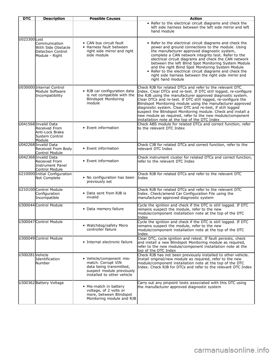
DTC Description Possible Causes Action Refer to the electrical circuit diagrams and check the
left side harness between the left side mirror and left
hand module U023300
Lost
Communication
With Side Obstacle
Detection Control
Module - Right
CAN bus circuit fault
Harness fault between
right side mirror and right
side module
Refer to the electrical circuit diagrams and check the
power and ground connections to the module. Using
the manufacturer approved diagnostic system,
complete a CAN network integrity test. Refer to the
electrical circuit diagrams and check the CAN network
between the left Blind Spot Monitoring System Module
and the right Blind Spot Monitoring System Module
Refer to the electrical circuit diagrams and check the
right side harness between the right side mirror and
right hand module U030000
Internal Control
Module Software
Incompatibility
RJB car configuration data
is not compatible with the
Blindspot Monitoring
module Check RJB for related DTCs and refer to the relevant DTC
Index. Clear DTCs and re-test. If DTC still logged, re-configure
the RJB using the manufacturer approved diagnostic system.
Clear DTCs and re-test. If DTC still logged, re-configure the
Blindspot Monitoring module using the manufacturer approved
diagnostic system. Clear DTC and re-test, if still logged
suspect the Blindspot Monitoring module. Check and install a
new module as required, refer to the new module/component
installation note at the top of the DTC Index U041568
Invalid Data
Received From
Anti-Lock Brake
System Control
Module
Event information Check ABS module for related DTCs and correct function, refer
to the relevant DTC Index U042268
Invalid Data
Received From Body
Control Module
Event information Check CJB for related DTCs and correct function, refer to the
relevant DTC Index U042368
Invalid Data
Received From
Instrument Panel
Control Module
Event information Check instrument cluster for related DTCs and correct function,
refer to the relevant DTC Index U210000
Initial Configuration
Not Complete
No configuration has been
previously set Check RJB for related DTCs and refer to the relevant DTC
Index U210100
Control Module
Configuration
Incompatible
Data sent from RJB is
invalid Check RJB for related DTCs and refer to the relevant DTC
Index. Check/amend Car Configuration File using the
manufacturer approved diagnostic system U300044 Control Module
Data memory failure Cycle the ignition and check if the DTC is still logged. If DTC
remains suspect the module, refer to the new
module/component installation note at the top of the DTC
Index U300047 Control Module
Watchdog/safety Micro
controller failure Cycle the ignition and check if the DTC is still logged. If DTC
remains suspect the module, refer to the new
module/component installation note at the top of the DTC
Index U300049 Control Module
Internal electronic failure Clear DTC, cycle ignition and retest. If fault persists, check
and install a new Blindspot Monitoring module as required,
refer to the new module/component installation note at the top of the DTC Index U300281
Vehicle
Identification
Number
Vehicle/component mis-
match. Corrupt VIN
data being transmitted,
suspect module previously
installed to other vehicle Check RJB has not been previously installed to other vehicle.
Install original/new module as required, refer to the new
module/component installation note at the top of the DTC
Index. Check RJB for DTCs and refer to the relevant DTC Index U300362 Battery Voltage
Mis-match in battery
voltage, of 2 volts or
more, between Blindspot
Monitoring module and RJB Carry out any pinpoint tests associated with this DTC using
the manufacturer approved diagnostic system
Page 1840 of 3039
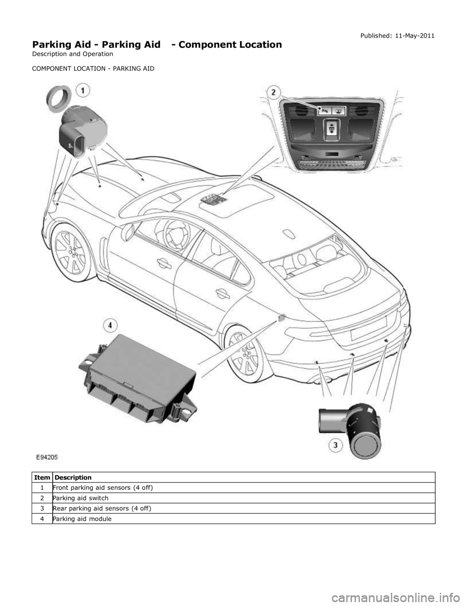
Parking Aid - Parking Aid - Component Location
Description and Operation
COMPONENT LOCATION - PARKING AID Published: 11-May-2011
Item Description 1 Front parking aid sensors (4 off) 2 Parking aid switch 3 Rear parking aid sensors (4 off) 4 Parking aid module
Page 1843 of 3039
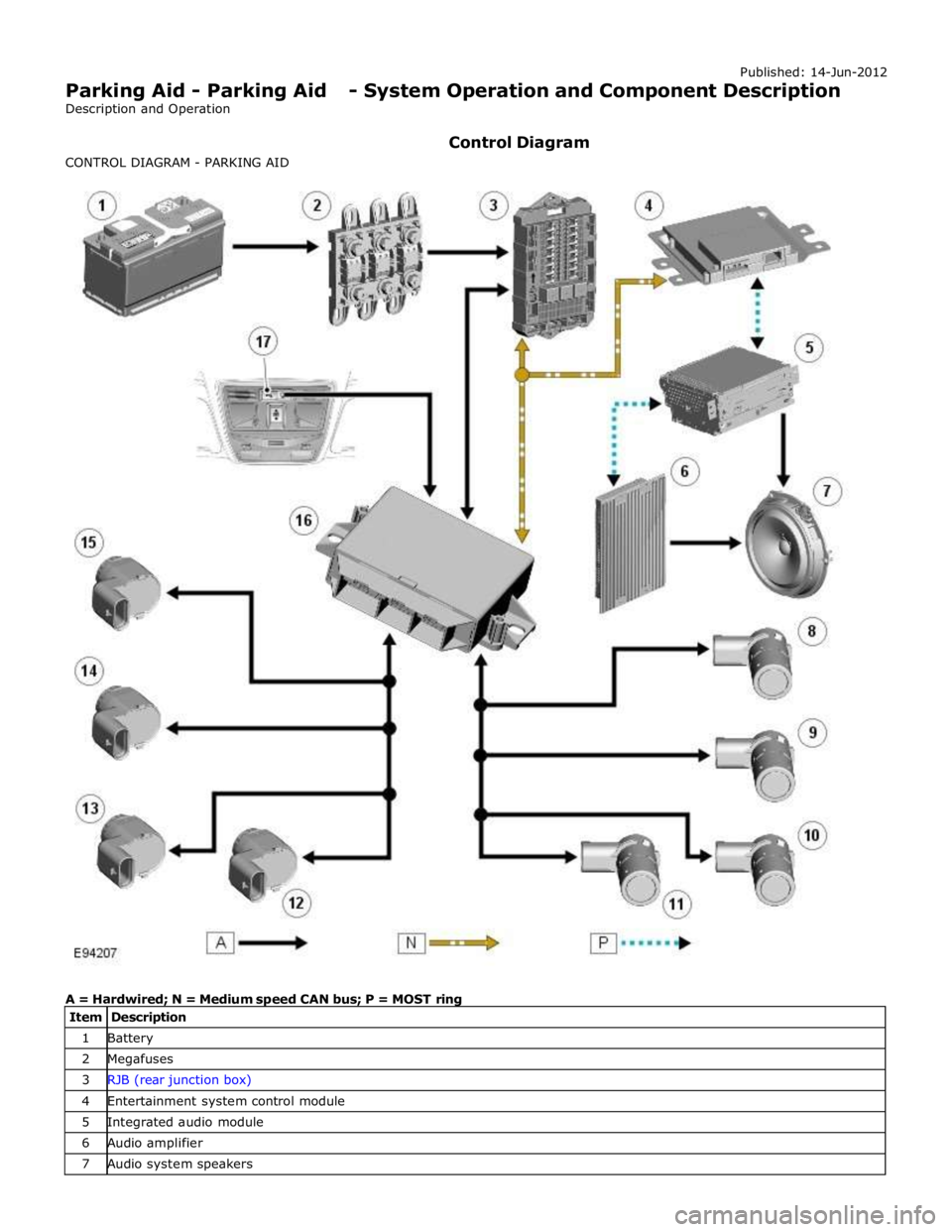
1 Battery 2 Megafuses 3 RJB (rear junction box) 4 Entertainment system control module 5 Integrated audio module 6 Audio amplifier 7 Audio system speakers
Page 1844 of 3039
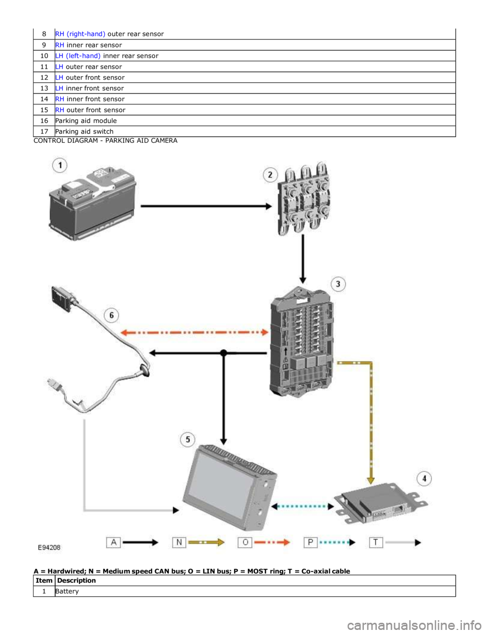
9 RH inner rear sensor 10 LH (left-hand) inner rear sensor 11 LH outer rear sensor 12 LH outer front sensor 13 LH inner front sensor 14 RH inner front sensor 15 RH outer front sensor 16 Parking aid module 17 Parking aid switch CONTROL DIAGRAM - PARKING AID CAMERA
A = Hardwired; N = Medium speed CAN bus; O = LIN bus; P = MOST ring; T = Co-axial cable
Item Description 1 Battery
Page 1845 of 3039
3 RJB 4 Entertainment system control module 5 Touch Screen Display (TSD) 6 Parking aid camera
PARKING AID System Operation
Two levels of parking aid system can be fitted; a rear only system or a front and rear system.
The parking aid module receives and ignition power mode 6 supply from the RJB. The parking aid module is connected to the entertainment system control module by the medium speed CAN (controller area
network) bus and the Media Orientated System Transport (MOST). The entertainment system is used by the parking aid system
to provide the driver with an audible warning. If an obstacle is sensed by the rear parking aid sensors, the rear audio system
speakers will sound. If an obstacle is sensed by the front parking aid sensors (if fitted), the front audio system speakers will
sound.
The parking aid system operates using ultrasonic signals which are transmitted by the sensors. The reflected echo from this
output is received by the sensors and used by the parking aid module to calculate the distance from an object.
When the parking aid module activates the system, the switch LED (light emitting diode) is illuminated to indicate that the
system is operating. The parking aid module then processes signals received from the sensors to determine if there is an
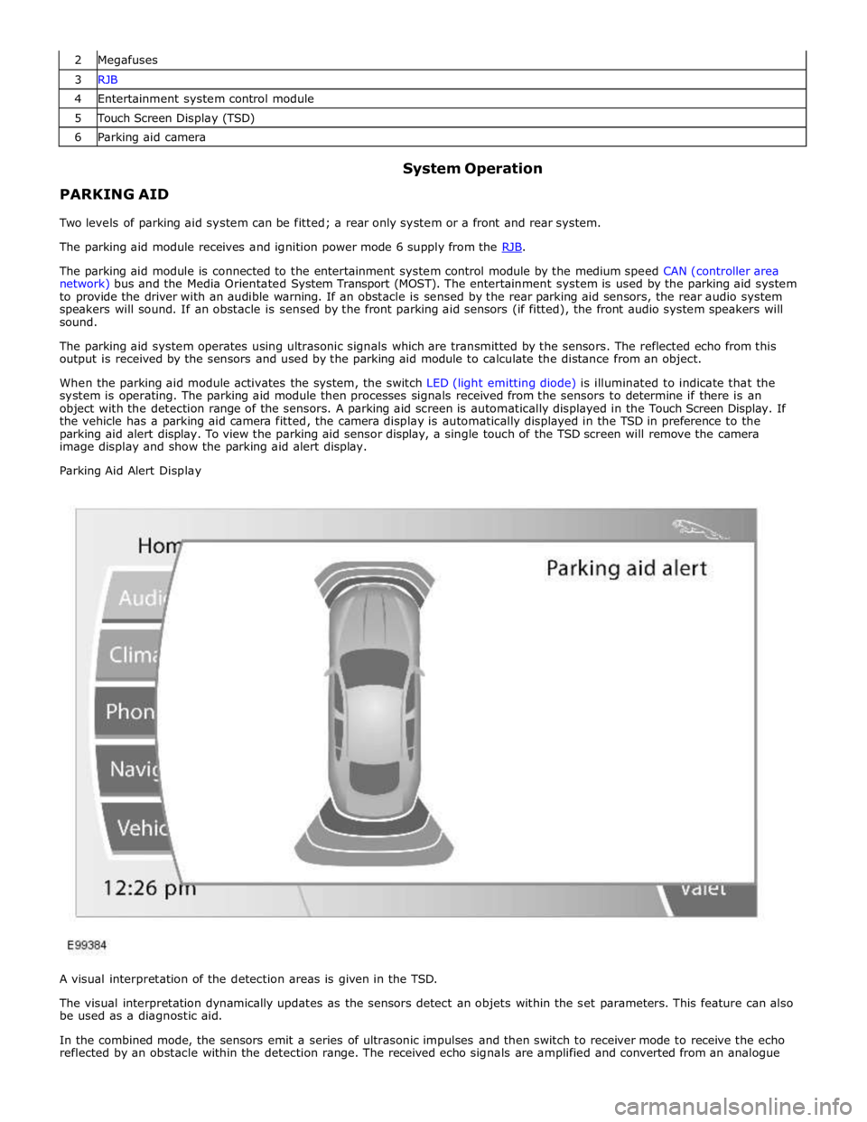
object with the detection range of the sensors. A parking aid screen is automatically displayed in the Touch Screen Display. If
the vehicle has a parking aid camera fitted, the camera display is automatically displayed in the TSD in preference to the
parking aid alert display. To view the parking aid sensor display, a single touch of the TSD screen will remove the camera
image display and show the parking aid alert display.
Parking Aid Alert Display
A visual interpretation of the detection areas is given in the TSD.
The visual interpretation dynamically updates as the sensors detect an objets within the set parameters. This feature can also
be used as a diagnostic aid.
In the combined mode, the sensors emit a series of ultrasonic impulses and then switch to receiver mode to receive the echo
reflected by an obstacle within the detection range. The received echo signals are amplified and converted from an analogue