2010 JAGUAR XFR Engine
[x] Cancel search: EnginePage 1429 of 3039
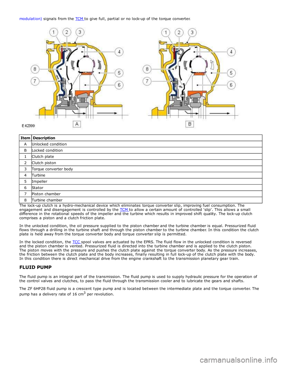
Item Description A Unlocked condition B Locked condition 1 Clutch plate 2 Clutch piston 3 Torque converter body 4 Turbine 5 Impeller 6 Stator 7 Piston chamber 8 Turbine chamber The lock-up clutch is a hydro-mechanical device which eliminates torque converter slip, improving fuel consumption. The
engagement and disengagement is controlled by the TCM to allow a certain amount of controlled 'slip'. This allows a small difference in the rotational speeds of the impeller and the turbine which results in improved shift quality. The lock-up clutch
comprises a piston and a clutch friction plate.
In the unlocked condition, the oil pressure supplied to the piston chamber and the turbine chamber is equal. Pressurized fluid
flows through a drilling in the turbine shaft and through the piston chamber to the turbine chamber. In this condition the clutch
plate is held away from the torque converter body and torque converter slip is permitted.
In the locked condition, the TCC spool valves are actuated by the EPRS. The fluid flow in the unlocked condition is reversed and the piston chamber is vented. Pressurized fluid is directed into the turbine chamber and is applied to the clutch piston.
The piston moves with the pressure and pushes the clutch plate against the torque converter body. As the pressure increases,
the friction between the clutch plate and the body increases, finally resulting in full lock-up of the clutch plate with the body.
In this condition there is direct mechanical drive from the engine crankshaft to the transmission planetary gear train.
FLUID PUMP
The fluid pump is an integral part of the transmission. The fluid pump is used to supply hydraulic pressure for the operation of
the control valves and clutches, to pass the fluid through the transmission cooler and to lubricate the gears and shafts.
The ZF 6HP28 fluid pump is a crescent type pump and is located between the intermediate plate and the torque converter. The
pump has a delivery rate of 16 cm3
per revolution.
Page 1431 of 3039
transmission functions. The Mechatronic valve block comprises the following components:
TCM
Pressure regulator solenoids
Shift control solenoid
Damper
Hydraulic spool valves
Selector valve
Temperature sensor
Turbine speed sensor
Output shaft speed sensor.
Sensors
Speed Sensors
The turbine speed sensor and the output shaft speed sensor are Hall effect type sensors located in the Mechatronic valve block
and are not serviceable items. The TCM monitors the signals from each sensor to determine the input (turbine) speed and the output shaft speed.
The turbine speed is monitored by the TCM to calculate the slip of the torque converter clutch and internal clutch slip. This signal allows the TCM to accurately control the slip timing during shifts and adjust clutch application or release pressure for overlap shift control.
The output shaft speed is monitored by the TCM and compared to engine speed signals received on the CAN bus from the ECM. Using a comparison of the two signals the TCM calculates the transmission slip ratio for plausibility and maintains adaptive pressure control.
Temperature Sensor
The temperature sensor is also located in the Mechatronic valve block. The TCM uses the temperature sensor signals to determine the temperature of the transmission fluid. These signals are used by the TCM to control the transmission operation to promote faster warm-up in cold conditions or to assist with fluid cooling by controlling the transmission operation when high
fluid temperatures are experienced. If the sensor fails, the TCM will use a default value and a fault code will be stored in the TCM.
Damper
There is one damper located in the valve housing. The damper is used to regulate and dampen the regulated pressure supplied
via EPRS. The damper is load dependent through modulation of the damper against return spring pressure.
The damper comprises a piston, a housing bore and a spring. The piston is subject to the pressure applied by the spring. The
bore has a connecting port to the function to which it applies. Fluid pressure applied to the applicable component (i.e. a
clutch) is also subjected to the full area of the piston, which moves against the opposing force applied by the spring. The
movement of the piston creates an action similar to a shock absorber, momentarily delaying the build up of pressure in the
circuit. This results in a more gradual application of clutches improving shift quality.
Spool Valves
The valve block spool valves control various functions of the transmission. The spool valves are of conventional design and are
operated by fluid pressure.
Each spool valve is located in its spool bore and held in a default (unpressurized) position by a spring. The spool bore has a
number of ports which allow fluid to flow to other valves and clutches to enable transmission operation. Each spool has a
piston which is waisted to allow fluid to be diverted into the applicable ports when the valve is operated.
When fluid pressure moves a spool, one or more ports in the spool bore are covered or uncovered. Fluid is prevented from
flowing or is allowed to flow around the applicable waisted area of the spool and into another uncovered port. The fluid is
either passed through galleries to actuate another spool, operate a clutch or is returned to the fluid pan.
Page 1432 of 3039
DRIVE CLUTCHES
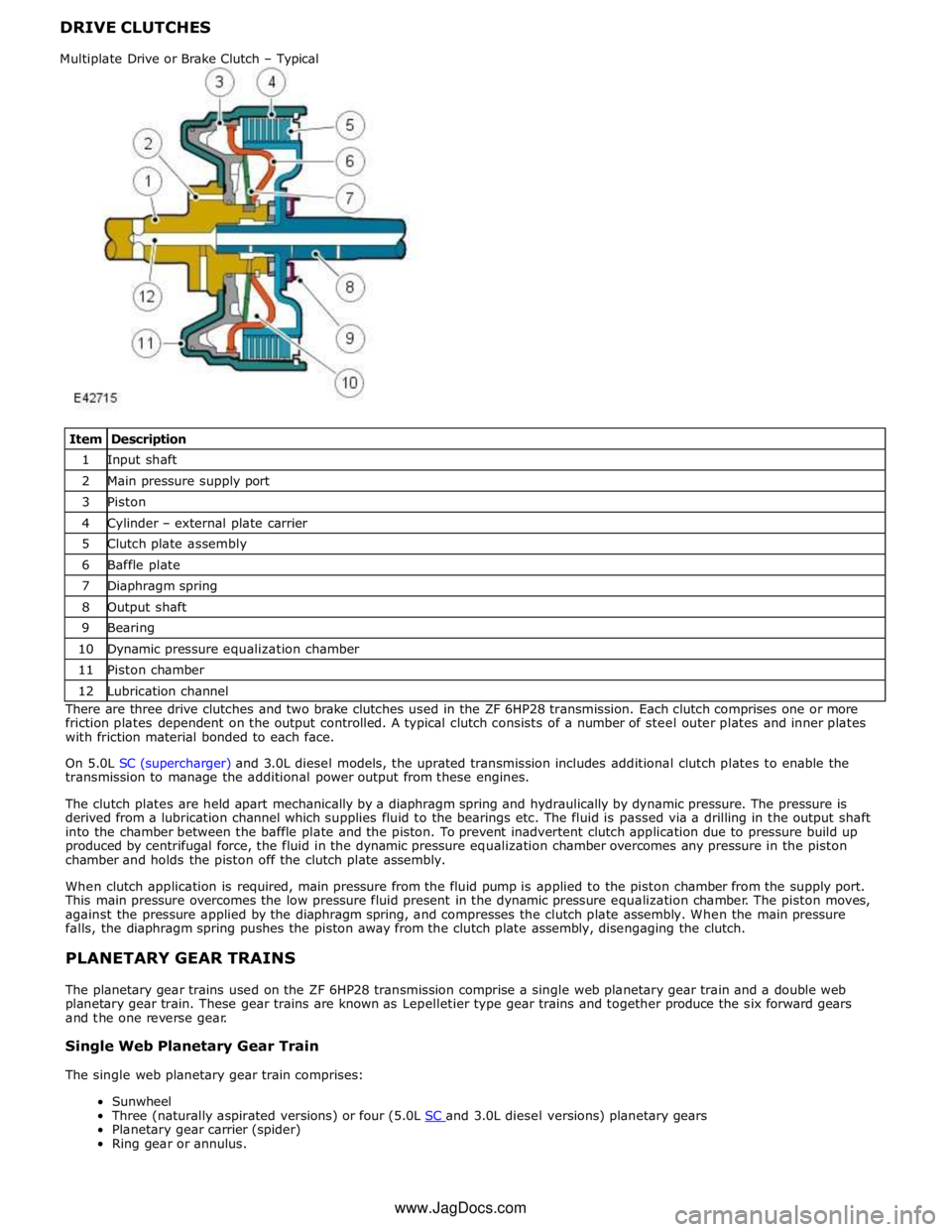
Item Description 1 Input shaft 2 Main pressure supply port 3 Piston 4 Cylinder – external plate carrier 5 Clutch plate assembly 6 Baffle plate 7 Diaphragm spring 8 Output shaft 9 Bearing 10 Dynamic pressure equalization chamber 11 Piston chamber 12 Lubrication channel There are three drive clutches and two brake clutches used in the ZF 6HP28 transmission. Each clutch comprises one or more
friction plates dependent on the output controlled. A typical clutch consists of a number of steel outer plates and inner plates
with friction material bonded to each face.
On 5.0L SC (supercharger) and 3.0L diesel models, the uprated transmission includes additional clutch plates to enable the
transmission to manage the additional power output from these engines.
The clutch plates are held apart mechanically by a diaphragm spring and hydraulically by dynamic pressure. The pressure is
derived from a lubrication channel which supplies fluid to the bearings etc. The fluid is passed via a drilling in the output shaft
into the chamber between the baffle plate and the piston. To prevent inadvertent clutch application due to pressure build up
produced by centrifugal force, the fluid in the dynamic pressure equalization chamber overcomes any pressure in the piston
chamber and holds the piston off the clutch plate assembly.
When clutch application is required, main pressure from the fluid pump is applied to the piston chamber from the supply port.
This main pressure overcomes the low pressure fluid present in the dynamic pressure equalization chamber. The piston moves,
against the pressure applied by the diaphragm spring, and compresses the clutch plate assembly. When the main pressure
falls, the diaphragm spring pushes the piston away from the clutch plate assembly, disengaging the clutch.
PLANETARY GEAR TRAINS
The planetary gear trains used on the ZF 6HP28 transmission comprise a single web planetary gear train and a double web
planetary gear train. These gear trains are known as Lepelletier type gear trains and together produce the six forward gears
and the one reverse gear.
Single Web Planetary Gear Train
The single web planetary gear train comprises:
Sunwheel
Three (naturally aspirated versions) or four (5.0L SC and 3.0L diesel versions) planetary gears Planetary gear carrier (spider)
Ring gear or annulus. Multiplate Drive or Brake Clutch – Typical www.JagDocs.com
Page 1435 of 3039
Published: 25-Aug-2011
Automatic Transmission/Transaxle - TDV6 3.0L Diesel /V8 5.0L Petrol/V8 S/C 5.0L Petrol - Diagnostics
Diagnosis and Testing
Principle of Operation
For a detailed description of the automatic transmission/transaxle, refer to the relevant Description and Operation section n
the workshop manual. REFER to: (307-01B Automatic Transmission/Transaxle - TDV6 3.0L Diesel /V8 5.0L Petrol/V8 S/C 5.0L
Petrol)
Transmission Description (Description and Operation), Transmission Description (Description and Operation), Transmission Description (Description and Operation).
Fluid Level and Condition Check
CAUTION: The vehicle should not be driven if the fluid level is low as internal failure can result.
NOTE: The transmission fluid temperature must not be allowed to exceed 50°C (122°F) whilst checking level. Should the
temperature rise above this figure, abort the check and allow the transmission fluid to cool to below 30°C (86°F).
This vehicle is not equipped with a fluid level indicator. An incorrect level may affect the transmission operation and could
result in transmission damage. To correctly check and add fluid to the transmission.
REFER to: Transmission Fluid Level Check (307-01B Automatic Transmission/Transaxle - TDV6 3.0L Diesel /V8 5.0L Petrol/V8 S/C 5.0L Petrol, General Procedures).
High Fluid Level
A fluid level that is too high may cause the fluid to become aerated due to the churning action of the rotating internal parts.
This will cause erratic control pressure, foaming, loss of fluid from the vent tube and possible transmission damage. If an
overfill condition is identified, with the engine at idle ensure the fluid temperature is within the specified range and allow the
excess fluid to drain until a small thread of fluid runs from the filler/level plug hole.
Low Fluid Level
A low fluid level could result in poor transmission engagement, slipping, or damage. This could also indicate a leak in one of
the transmission seals or gaskets.
REFER to: Transmission Fluid Level Check (307-01B Automatic Transmission/Transaxle - TDV6 3.0L Diesel /V8 5.0L Petrol/V8 S/C 5.0L Petrol, General Procedures).
Adding Fluid
CAUTION: The use of any other type of transmission fluid other than that specified can result in transmission damage.
If fluid needs to be added, add fluid in 0.50 liter increments through the fill hole Opening. Do not overfill the fluid. For fluid
type, refer to the General Specification chart in this section.
REFER to: Specifications (307-01B Automatic Transmission/Transaxle - TDV6 3.0L Diesel /V8 5.0L Petrol/V8 S/C 5.0L Petrol, Specifications).
Fluid Condition Check
1. Check the fluid level.
REFER to: Transmission Fluid Level Check (307-01B Automatic Transmission/Transaxle - TDV6 3.0L Diesel /V8 5.0L Petrol/V8 S/C 5.0L Petrol, General Procedures).
2. Observe the color and the odor of the fluid. The color under normal circumstances should be Honey.
3. Allow the fluid to drip onto a facial tissue and examine the stain.
4. If evidence of solid material is found, the transmission fluid pan should be removed for further inspection.
NOTE: In the event of a transmission unit replacement for internal failure, the oil cooler and pipes must also be replaced.
Inspection and Verification
1. Verify the customer concern.
2. Visually inspect for obvious signs of damage and system integrity.
Page 1436 of 3039
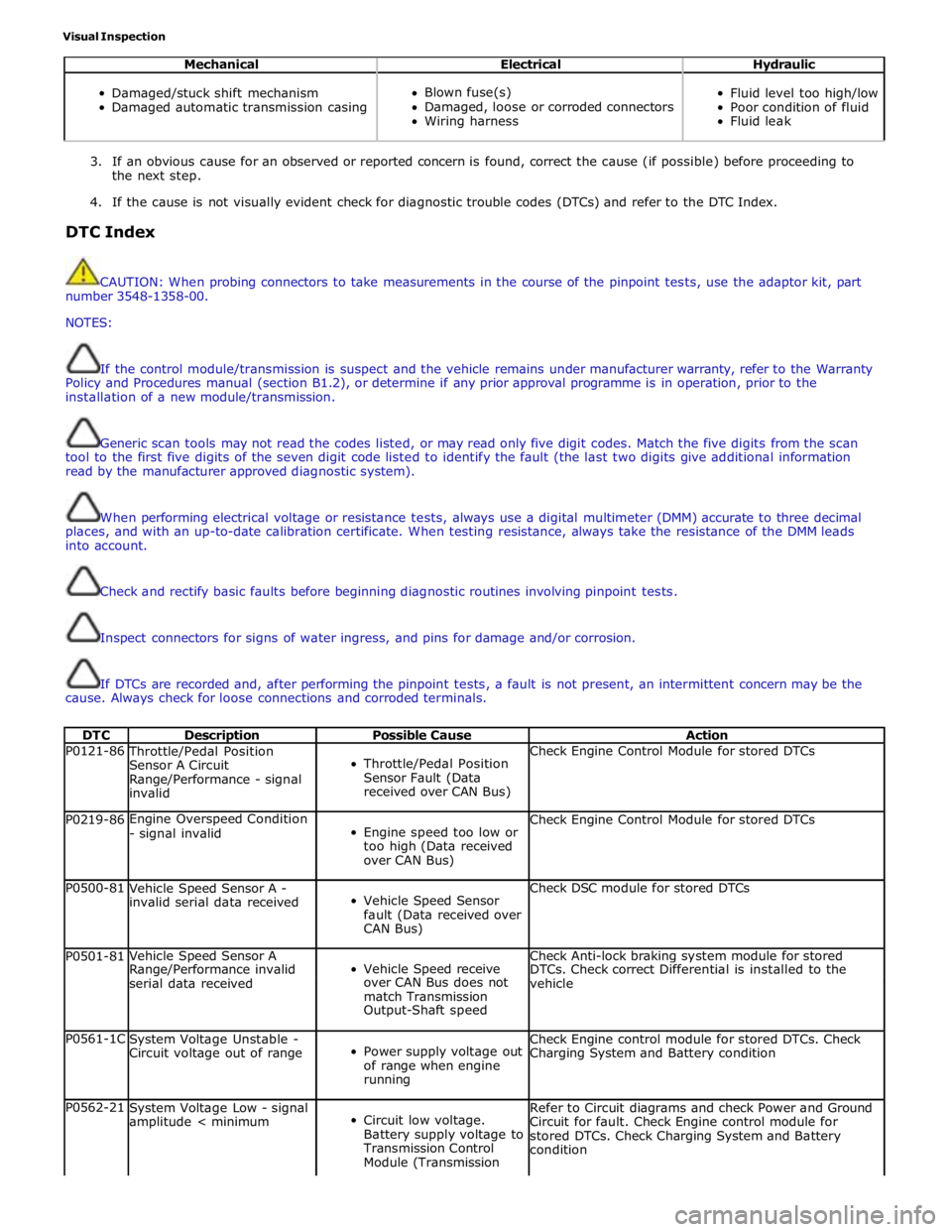
Visual Inspection
Mechanical Electrical Hydraulic
Damaged/stuck shift mechanism
Damaged automatic transmission casing
Blown fuse(s)
Damaged, loose or corroded connectors
Wiring harness
Fluid level too high/low
Poor condition of fluid
Fluid leak
3. If an obvious cause for an observed or reported concern is found, correct the cause (if possible) before proceeding to
the next step.
4. If the cause is not visually evident check for diagnostic trouble codes (DTCs) and refer to the DTC Index.
DTC Index
CAUTION: When probing connectors to take measurements in the course of the pinpoint tests, use the adaptor kit, part
number 3548-1358-00.
NOTES:
If the control module/transmission is suspect and the vehicle remains under manufacturer warranty, refer to the Warranty
Policy and Procedures manual (section B1.2), or determine if any prior approval programme is in operation, prior to the
installation of a new module/transmission.
Generic scan tools may not read the codes listed, or may read only five digit codes. Match the five digits from the scan
tool to the first five digits of the seven digit code listed to identify the fault (the last two digits give additional information
read by the manufacturer approved diagnostic system).
When performing electrical voltage or resistance tests, always use a digital multimeter (DMM) accurate to three decimal
places, and with an up-to-date calibration certificate. When testing resistance, always take the resistance of the DMM leads
into account.
Check and rectify basic faults before beginning diagnostic routines involving pinpoint tests.
Inspect connectors for signs of water ingress, and pins for damage and/or corrosion.
If DTCs are recorded and, after performing the pinpoint tests, a fault is not present, an intermittent concern may be the
cause. Always check for loose connections and corroded terminals.
DTC Description Possible Cause Action P0121-86 Throttle/Pedal Position
Sensor A Circuit
Range/Performance - signal
invalid
Throttle/Pedal Position
Sensor Fault (Data
received over CAN Bus) Check Engine Control Module for stored DTCs P0219-86 Engine Overspeed Condition
- signal invalid
Engine speed too low or
too high (Data received
over CAN Bus) Check Engine Control Module for stored DTCs P0500-81
Vehicle Speed Sensor A -
invalid serial data received
Vehicle Speed Sensor
fault (Data received over
CAN Bus) Check DSC module for stored DTCs P0501-81 Vehicle Speed Sensor A
Vehicle Speed receive Check Anti-lock braking system module for stored Range/Performance invalid DTCs. Check correct Differential is installed to the serial data received over CAN Bus does not
vehicle match Transmission Output-Shaft speed P0561-1C
System Voltage Unstable -
Circuit voltage out of range
Power supply voltage out
of range when engine
running Check Engine control module for stored DTCs. Check
Charging System and Battery condition P0562-21
System Voltage Low - signal
amplitude < minimum
Circuit low voltage.
Battery supply voltage to
Transmission Control
Module (Transmission Refer to Circuit diagrams and check Power and Ground
Circuit for fault. Check Engine control module for
stored DTCs. Check Charging System and Battery
condition
Page 1437 of 3039

DTC Description Possible Cause Action control module)
P0563-22
System Voltage High - signal
amplitude > maximum
High Battery charge,
alternator fault Check Engine control module for stored DTCs. Check
Charging System and Battery condition P0601-41
Internal Control Module
Memory Check Sum Error -
general checksum failure
Software error
Transmission control
module failure Re-configure the Transmission control module using
the manufacturer approved diagnostic system, clear
DTC and re-test. If DTC remains, Suspect the
Transmission control module. Install a new
Transmission control module as required, refer to the
new module/component installation note at the top of
the DTC Index P0604-00
Internal Control Module
Random Access Memory
(RAM) Error - no sub type
information
Shift-by-Wire fault Suspect the Transmission control module. Install a
new Transmission control module as required, refer to
the new module/component installation note at the top of the DTC Index P0605-41
Internal Control Module
Read Only Memory (ROM)
Error - general checksum
failure
General checksum failure Suspect the Transmission control module. Install a
new Transmission control module as required, refer to
the new module/component installation note at the top of the DTC Index P0606-04 Transmission control module
Processor - System Internal
Failures
Micro controller
component faults Suspect the Transmission control module. Install a
new Transmission control module as required, refer to
the new module/component installation note at the top of the DTC Index P0606-26 Transmission control module
Processor - signal rate of
change below threshold
Micro controller
component faults Suspect the Transmission control module. Install a
new Transmission control module as required, refer to
the new module/component installation note at the top of the DTC Index P0606-49 Transmission control module
Processor-internal electronic
failure
Micro controller
component faults Suspect the Transmission control module. Install a
new Transmission control module as required, refer to
the new module/component installation note at the top of the DTC Index P0613-04 Transmission control module
Processor - System Internal
Failures
Micro controller
component faults Suspect the Transmission control module. Install a
new Transmission control module as required, refer to
the new module/component installation note at the top of the DTC Index P0613-06 Transmission control module
Processor - Algorithm Based
Failures
Micro controller
component faults Suspect the Transmission control module. Install a
new Transmission control module as required, refer to
the new module/component installation note at the top of the DTC Index P0613-11 Transmission control module
Processor - Circuit Short to
Ground
Watchdog fault Suspect the Transmission control module. Install a
new Transmission control module as required, refer to
the new module/component installation note at the top of the DTC Index P0613-12 Transmission control module
Processor - Circuit Short to
Battery
Watchdog fault Suspect the Transmission control module. Install a
new Transmission control module as required, refer to
the new module/component installation note at the top of the DTC Index P0613-13 Transmission control module
Processor - Circuit Open
Watchdog fault Suspect the Transmission control module. Install a
new Transmission control module as required, refer to
the new module/component installation note at the top of the DTC Index P0613-14 Transmission control module
Processor - Circuit Short to
Ground or Open
Watchdog fault Suspect the Transmission control module. Install a
new Transmission control module as required, refer to
the new module/component installation note at the top of the DTC Index P0613-21 Transmission control module
Processor - signal amplitude
< minimum
Watchdog fault Suspect the Transmission control module. Install a
new Transmission control module as required, refer to
the new module/component installation note at the top of the DTC Index P0613-22 Transmission control module
Processor - signal amplitude
> maximum
Watchdog fault Suspect the Transmission control module. Install a
new Transmission control module as required, refer to
the new module/component installation note at the top of the DTC Index P0613-47 Transmission control module
Processor - watchdog /
safety Micro controller
failure
Watchdog fault Suspect the Transmission control module. Install a
new Transmission control module as required, refer to
the new module/component installation note at the top of the DTC Index P0613-49 Transmission control module
Processor - internal
electronic failure
Micro controller
component faults Suspect the Transmission control module. Install a
new Transmission control module as required, refer to
the new module/component installation note at the top of the DTC Index P0613-68 Transmission control module
Processor-Event Information
Watchdog fault Suspect the Transmission control module. Install a
new Transmission control module as required, refer to
the new module/component installation note at the top of the DTC Index www.JagDocs.com
Page 1438 of 3039

DTC Description Possible Cause Action P061B-02
Internal Control Module Torque Calculation
Performance - general signal
failure
Transmission control
module - positive torque
signal not valid Suspect the Transmission control module. Install a
new Transmission control module as required, refer to
the new module/component installation note at the
top of the DTC Index P061B-26
Internal Control Module Torque Calculation
Performance - signal rate of
change below threshold
Transmission control
module positive torque
signal not valid Suspect the Transmission control module. Install a
new Transmission control module as required, refer to
the new module/component installation note at the
top of the DTC Index P062F-04
Internal Control Module
EEPROM Error - System
Internal Failures
EEPROM communication
error Suspect the Transmission control module. Install a
new Transmission control module as required, refer to
the new module/component installation note at the top of the DTC Index P0642-21
Sensor Reference Voltage A
Circuit Low - signal
amplitude < minimum
Sensor supply voltage
fault low Suspect the Transmission control module. Install a
new Transmission control module as required, refer to
the new module/component installation note at the top of the DTC Index P0643-22
Sensor Reference Voltage A
Circuit High - signal
amplitude > maximum
Sensor supply voltage
fault high Suspect the Transmission control module. Install a
new Transmission control module as required, refer to
the new module/component installation note at the top of the DTC Index P0657-13
Actuator Supply Voltage A
Circuit / Open - Circuit Open
Actuator supply (pressure
control valves etc) Open
Circuit Suspect the Transmission control module. Install a
new Transmission control module as required, refer to
the new module/component installation note at the
top of the DTC Index P0657-1C
Actuator Supply Voltage A
Circuit / Open - Circuit
voltage out of range
Actuator supply (pressure
control valves etc)
voltage plausibility fault Refer to electrical Circuit diagrams and check
Transmission control module connector for signs of
water ingress or damage, check pin 7 for Short to
Power or Ground (should NOT be connected and
harness terminal should have a bung fitted). If no
fault identified, suspect the Transmission control
module. Check and install a new Transmission control
module as required, refer to the new
module/component installation note at the top of the
DTC Index P0658-11
Actuator Supply Voltage A
Circuit Low - Circuit Short to
Ground
Actuator supply (pressure
control valves etc)
voltage Short to Ground Suspect the Transmission control module. Install a
new Transmission control module as required, refer to
the new module/component installation note at the
top of the DTC Index P0659-12
Actuator Supply Voltage A
Circuit High - Circuit Short to
Battery
Actuator supply (pressure
control valves etc)
voltage Short to Power Suspect the Transmission control module. Install a
new Transmission control module as required, refer to
the new module/component installation note at the
top of the DTC Index P0667-01 PCM / Engine control module / Transmission control
module Internal Temperature
Sensor A Range/Performance
- General Electrical Failure
General electrical failure Suspect the Transmission control module. Install a
new Transmission control module as required, refer to
the new module/component installation note at the
top of the DTC Index P0667-04 PCM / Engine control module / Transmission control
module Internal Temperature
Sensor A Range/Performance
- System Internal Failures
Internal Electronic Failure Suspect the Transmission control module. Install a
new Transmission control module as required, refer to
the new module/component installation note at the
top of the DTC Index P0667-49 PCM / Engine control module / Transmission control
module Internal Temperature
Sensor A Range/Performance
- internal electronic failure
Internal electronic failure Suspect the Transmission control module. Install a
new Transmission control module as required, refer to
the new module/component installation note at the
top of the DTC Index P0700-02 Transmission Control System
(MIL Request) - General signal failure
General Signal failure Clear DTC, Road test and re-test, Read DTCs and
Investigate as required P0700-22 Transmission Control System
(MIL Request) - signal
amplitude > maximum
Double fault from
monitoring of internal
power supply and
pressure
regulator/solenoid
control software If any of the following DTCs are also present;
P074013, P096712, P273912, P273012, P272112,
P096312, P276312, P097112, suspect the Transmission
control module, check and install a new Transmission
control module as required, refer to the new
module/component installation note at the top of the
DTC Index P0700-75 Transmission Control System
(MIL Request) - Emergency
Position Not Reachable
Emergency Position Not
Reachable Clear DTC, Road test and re-test, Read DTCs and
investigate as required
Page 1446 of 3039

DTC Description Possible Cause Action P2764-11 Torque Converter Clutch
Pressure Control Solenoid
Control Circuit Low - Circuit
Short to Ground
Torque converter clutch
pressure control solenoid
control Circuit Short to
Ground Suspect the Transmission control module. Install a
new Transmission control module as required, refer to
the new module/component installation note at the
top of the DTC Index P2764-1A Torque Converter Clutch
Pressure Control Solenoid
Control Circuit Low-Circuit
Resistance Below Threshold
Torque converter clutch
pressure control solenoid
control circuit resistance
below threshold Suspect the Transmission control module. Install a
new Transmission control module as required, refer to
the new module/component installation note at the
top of the DTC Index P2764-1E Torque Converter Clutch
Pressure Control Solenoid
Control Circuit Low-Circuit
Resistance Out Of Range
Torque converter clutch
pressure control solenoid
control circuit resistance
out of range Suspect the Transmission control module. Install a
new Transmission control module as required, refer to
the new module/component installation note at the
top of the DTC Index P2807-11 Pressure Control Solenoid G
- Circuit Short to Ground
Park solenoid Circuit
Short to Ground Suspect the Transmission control module. Install a
new Transmission control module as required, refer to
the new module/component installation note at the top of the DTC Index P2807-12 Pressure Control Solenoid G
- Circuit Short to Battery
Park solenoid Circuit
Short to Power Suspect the Transmission control module. Install a
new Transmission control module as required, refer to
the new module/component installation note at the top of the DTC Index P2807-13 Pressure Control Solenoid G
- Circuit Open
Park solenoid Circuit
Open Circuit Suspect the Transmission control module. Install a
new Transmission control module as required, refer to
the new module/component installation note at the top of the DTC Index P2807-14 Pressure Control Solenoid G
- Circuit Short to Ground or
Open
Park solenoid Circuit
Short to Ground or Open
Circuit Carry out any diagnostic pinpoint tests associated
with this DTC using the manufacturer approved
diagnostic system. Suspect the Transmission control
module. Install a new Transmission control module as
required, refer to the new module/component
installation note at the top of the DTC Index B1087-82
LIN Bus "A" - alive /
sequence counter incorrect /
not updated
Alive counter fault Check Transmission Shift Module for stored DTCs.
Refer to the electrical Circuit diagrams and check
Transmission control module to Transmission Shift
Module for Short to Ground or Open Circuit (LIN Bus) B1087-83
LIN Bus "A" - value of signal
protection calculation
incorrect
Checksum error Check Transmission Shift Module for stored DTCs Refer
to the electrical Circuit diagrams and check
Transmission control module to Transmission Shift
Module for Short to Ground or Open Circuit (LIN Bus) B1087-87
LIN Bus "A" - missing
message
GSM is NOT visible to the
Transmission control
module on the LIN Bus Check Transmission Shift Module for stored DTCs Refer
to the electrical Circuit diagrams and check
Transmission control module to Transmission Shift
Module for Short or Open Circuit (LIN Bus) B1087-88 LIN Bus "A" - Bus off
LIN Bus Circuit fault.
Check hardware of LIN
connection between
transmission and GSM Refer to the electrical Circuit diagrams and check
Transmission control module to Transmission shift
module for Short, Open Circuit (LIN Bus). Check
Transmission Shift Module for related DTCs U0001-88
High Speed CAN
Communication Bus - Bus off
CAN Bus off Refer to the electrical Circuit diagrams and check CAN
Bus for Circuit fault U0100-82
Lost Communication With
Engine control module/PCM
"A" - alive / sequence
counter incorrect / not updated
Alive counter fault Check Engine control module for stored DTCs U0100-83
Lost Communication With
Engine control module/PCM
"A" - value of signal
protection calculation
incorrect
Checksum fault Check Engine control module for stored DTCs U0100-87
Lost Communication With
Engine control module/PCM
"A" - missing message
CAN Timeout
NOTE: Do NOT install a new Engine control
module if an Engine control module Timeout DTC is
only logged in the Transmission control module, the
failure is NOT with the Engine control module
Check Engine control module for stored DTCs. Check
CAN Bus Circuit for fault