2010 JAGUAR XFR steering wheel adjustment
[x] Cancel search: steering wheel adjustmentPage 2171 of 3039

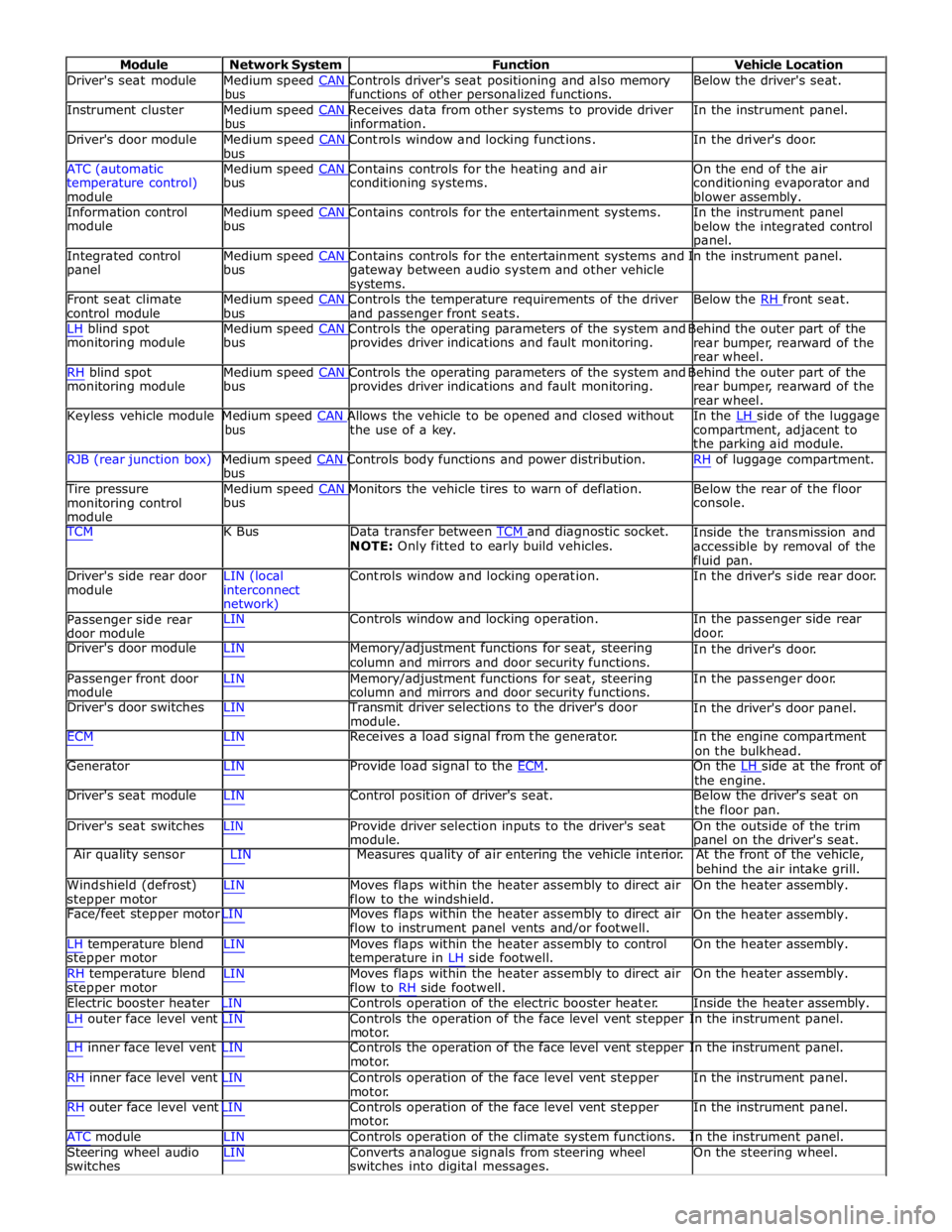
Module Network System Function Vehicle Location
Driver's seat module Medium speed CAN Controls driver's seat positioning and also memory Below the driver's seat. bus functions of other personalized functions.
Instrument cluster Medium speed CAN Receives data from other systems to provide driver In the instrument panel. bus information.
Driver's door module Medium speed CAN Controls window and locking functions. In the driver's door. bus
ATC (automatic Medium speed CAN Contains controls for the heating and air On the end of the air
temperature control)
module bus conditioning systems.
conditioning evaporator and
blower assembly.
Information control Medium speed CAN Contains controls for the entertainment systems. In the instrument panel module bus
below the integrated control
panel.
Integrated control Medium speed CAN Contains controls for the entertainment systems and In the instrument panel. panel bus
gateway between audio system and other vehicle
systems.
Front seat climate Medium speed CAN Controls the temperature requirements of the driver Below the RH front seat. control module bus and passenger front seats.
LH blind spot Medium speed CAN Controls the operating parameters of the system and Behind the outer part of the monitoring module bus provides driver indications and fault monitoring.
rear bumper, rearward of the
rear wheel.
RH blind spot Medium speed CAN Controls the operating parameters of the system and Behind the outer part of the monitoring module bus provides driver indications and fault monitoring.
rear bumper, rearward of the
rear wheel.
Keyless vehicle module Medium speed CAN Allows the vehicle to be opened and closed without In the LH side of the luggage bus the use of a key.
compartment, adjacent to
the parking aid module.
RJB (rear junction box) Medium speed CAN Controls body functions and power distribution. RH of luggage compartment. bus
Tire pressure Medium speed CAN Monitors the vehicle tires to warn of deflation. Below the rear of the floor monitoring control
module bus console.
TCM K Bus Data transfer between TCM and diagnostic socket. NOTE: Only fitted to early build vehicles. Inside the transmission and
accessible by removal of the
fluid pan.
Driver's side rear door
module LIN (local
interconnect
network) Controls window and locking operation. In the driver's side rear door.
Passenger side rear
door module LIN Controls window and locking operation. In the passenger side rear
door.
Driver's door module LIN Memory/adjustment functions for seat, steering
column and mirrors and door security functions. In the driver's door.
Passenger front door
module LIN Memory/adjustment functions for seat, steering
column and mirrors and door security functions. In the passenger door.
Driver's door switches LIN Transmit driver selections to the driver's door
module. In the driver's door panel.
ECM LIN Receives a load signal from the generator. In the engine compartment
on the bulkhead.
Generator LIN Provide load signal to the ECM. On the LH side at the front of the engine.
Driver's seat module LIN Control position of driver's seat. Below the driver's seat on
the floor pan.
Driver's seat switches LIN Provide driver selection inputs to the driver's seat
module. On the outside of the trim
panel on the driver's seat.
Air quality sensor LIN Measures quality of air entering the vehicle interior. At the front of the vehicle,
behind the air intake grill.
Windshield (defrost)
stepper motor LIN Moves flaps within the heater assembly to direct air
flow to the windshield. On the heater assembly.
Face/feet stepper motor LIN Moves flaps within the heater assembly to direct air
flow to instrument panel vents and/or footwell. On the heater assembly.
LH temperature blend
stepper motor
RH temperature blend
stepper motor LIN Moves flaps within the heater assembly to control
temperature in LH side footwell.
LIN Moves flaps within the heater assembly to direct air
flow to RH side footwell. On the heater assembly.
On the heater assembly.
Electric booster heater LIN Controls operation of the electric booster heater. Inside the heater assembly.
LH outer face level vent LIN Controls the operation of the face level vent stepper In the instrument panel.
motor.
LH inner face level vent LIN Controls the operation of the face level vent stepper In the instrument panel.
motor.
RH inner face level vent LIN Controls operation of the face level vent stepper
motor.
RH outer face level vent LIN Controls operation of the face level vent stepper
motor. In the instrument panel.
In the instrument panel.
ATC module LIN Controls operation of the climate system functions. In the instrument panel.
Steering wheel audio
switches LIN Converts analogue signals from steering wheel
switches into digital messages. On the steering wheel.
Page 2316 of 3039

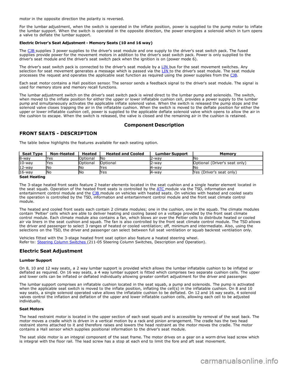
supplies provide power for the movement motors in addition to the driver's seat switch pack. Power is only supplied to the
driver's seat module and the driver's seat switch pack when the ignition is on (power mode 6).
The driver's seat switch pack is connected to the driver's seat module by a LIN bus for the seat movement switches. Any selection for seat movement generates a message which is passed via the LIN to the driver's seat module. The seat module processes the request and operates the applicable seat function as required using the power supplies from the CJB.
Each seat motor contains a Hall position sensor. The sensor sends a feedback signal to the driver's seat module. The signal is
used for memory store and memory recall functions.
The lumbar adjustment switch on the driver's seat switch pack is wired direct to the lumbar pump and solenoids. The switch,
when moved to the inflate position for either the upper or lower inflatable cushion cell, provides a power supply to the lumbar
pump and simultaneously activates the applicable inflate solenoid valve. When the switch is released the pump stops and the
solenoid valve closes trapping the air in the inflatable cushion. When the switch is moved to the deflate position for either the
upper or lower inflatable cushion cell, power is supplied to the applicable deflate solenoid valve which opens to allow the air in
the cushion to escape. When the switch is released, the valve is closed and the remaining air in the cushion is retained.
FRONT SEATS - DESCRIPTION Component Description
The table below highlights the features available for each seating option.
Seat Type Non-Heated Heated Heated and Cooled Lumbar Support Memory 8-way Yes Optional No 2-way No 10-way Yes Optional Optional 2-way Optional (Driver's seat only) 12-way No No Yes 4-way No 16-way No No Yes 4-way Yes (Driver's seat only) Seat Heating
The 3-stage heated front seats feature 2 heater elements located in the seat cushion and a single heater element located in
the seat squab. Operation of the heated front seats is controlled by the ATC module via the TSD, information and entertainment control module and the CJB module on vehicles with heated seats. On vehicles with heated and cooled seats the operation is controlled by the TSD, information and entertainment control module and the front seat climate control
module.
The heated and cooled front seats each contain 2 climate modules; one in the cushion, one in the squab. The climate modules
contain 'Peltier' cells which are able to deliver heating and cooling based on a voltage provided by the front seat climate
control module. Each climate module also contains a fan, which blows air over the Peltier cells to distribute heated or cooled
air via liners in the seat cushion and squab. The fan is also controlled by the front seat climate control module. The TSD allows
the driver and passenger to select 3 ranges of heated or cooled ventilation; off, minimum and intermediate. Also, using the
selections on the TSD, the driver and passenger can select between full seat ventilation or squab backrest ventilation only.
Vehicles fitted with the 3-stage heated front seat option also feature a heated steering wheel.
Refer to: Steering Column Switches (211-05 Steering Column Switches, Description and Operation).
Electric Seat Adjustment
Lumbar Support
On 8, 10 and 12 way seats, a 2 way lumbar support is provided which allows the lumbar inflatable cushion to be inflated or
deflated as required. On 16 way seats, a 4 way lumbar support is fitted which comprises two separate cushion cells. The upper
and lower cells can be inflated or deflated individually allowing greater comfort adjustment for the driver and passenger.
The lumbar support comprises an inflatable cushion located in the seat squab, a pump and solenoids. The pump is activated
when the applicable seat switch is moved to the inflate position, inflating the cell(s) in the inflatable cushion. On 8 and 10
way seats, a single solenoid operated valve allows the inflatable cushion to be deflated. On 12 and 16 way seats, 4 solenoid
valves control the inflation and deflation of the upper and lower inflatable cushion cells, allowing each cell to be adjusted
individually.
Seat Motors
The head restraint motor is located in the upper section of each seat squab and is accessible by removal of the seat back. The
motor moves a cradle which is driven in a vertical motion by a rack and pinion arrangement. The cradle has the two head
restraint stems attached to it and therefore raises and lowers the head restraint as the motor moves the cradle. The motor
contains a Hall sensor which supplies positional information to the driver's seat module.
The seat slide motor is an integral component of the seat frame. The motor drives on a gear on a worm drive lead screw which
is integral with the floor rail. The lead screw has a stop at each end to limit the fore and aft seat movement.
Page 2542 of 3039

On vehicles with headlamp powerwash, each headlamp assembly is fitted with a headlamp powerwasher. The powerwasher is
located on the underside of the headlamp assembly. The powerwasher is located in a clip at the front of the headlamp and
secured with 2 self tapping screws to the headlamp body.
The powerwasher is a telescopic unit which extends forwards from the headlamp assembly under washer fluid pressure
supplied by the headlamp powerwash pump. When the pump pressure decreases the powerwasher is automatically retracted
back into the housing. The outer end of the powerwasher is fitted with a trim which blends the powerwasher into the headlamp
when it is not operating. The powerwasher has two washer jets which direct washer fluid under high pressure onto the
headlamp lens when the powerwasher is extended.
RAIN/LIGHT SENSOR
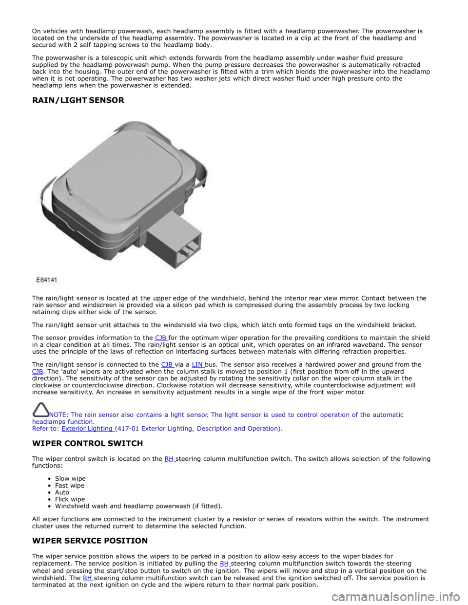
The rain/light sensor is located at the upper edge of the windshield, behind the interior rear view mirror. Contact between the
rain sensor and windscreen is provided via a silicon pad which is compressed during the assembly process by two locking
retaining clips either side of the sensor.
The rain/light sensor unit attaches to the windshield via two clips, which latch onto formed tags on the windshield bracket.
The sensor provides information to the CJB for the optimum wiper operation for the prevailing conditions to maintain the shield in a clear condition at all times. The rain/light sensor is an optical unit, which operates on an infrared waveband. The sensor
uses the principle of the laws of reflection on interfacing surfaces between materials with differing refraction properties.
The rain/light sensor is connected to the CJB via a LIN bus. The sensor also receives a hardwired power and ground from the CJB. The 'auto' wipers are activated when the column stalk is moved to position 1 (first position from off in the upward direction). The sensitivity of the sensor can be adjusted by rotating the sensitivity collar on the wiper column stalk in the
clockwise or counterclockwise direction. Clockwise rotation will decrease sensitivity, while counterclockwise adjustment will
increase sensitivity. An increase in sensitivity adjustment results in a single wipe of the front wiper motor.
NOTE: The rain sensor also contains a light sensor. The light sensor is used to control operation of the automatic
headlamps function.
Refer to: Exterior Lighting (417-01 Exterior Lighting, Description and Operation).
WIPER CONTROL SWITCH
The wiper control switch is located on the RH steering column multifunction switch. The switch allows selection of the following functions:
Slow wipe
Fast wipe
Auto
Flick wipe
Windshield wash and headlamp powerwash (if fitted).
All wiper functions are connected to the instrument cluster by a resistor or series of resistors within the switch. The instrument
cluster uses the returned current to determine the selected function.
WIPER SERVICE POSITION
The wiper service position allows the wipers to be parked in a position to allow easy access to the wiper blades for
replacement. The service position is initiated by pulling the RH steering column multifunction switch towards the steering wheel and pressing the start/stop button to switch on the ignition. The wipers will move and stop in a vertical position on the
windshield. The RH steering column multifunction switch can be released and the ignition switched off. The service position is terminated at the next ignition on cycle and the wipers return to their normal park position.