Page 1173 of 3039
Supercharger Cooling - V8 S/C 5.0L Petrol - Radiator
Removal and Installation
Removal
NOTE: Removal steps in this procedure may contain installation details. Published: 19-Nov-2013
1. Refer to: Battery Disconnect and Connect (414-01 Battery, Mounting and Cables, General Procedures).
2. Refer to: Air Cleaner LH (303-12C Intake Air Distribution and Filtering - V8 5.0L Petrol, Removal and Installation).
3. Refer to: Air Cleaner RH (303-12C Intake Air Distribution and Filtering - V8 5.0L Petrol, Removal and Installation).
4. NOTE: Some variation in the illustrations may occur, but
the essential information is always correct.
Torque: 9 Nm
5. CAUTION: Be prepared to collect escaping coolant.
Page 1644 of 3039

1 Set speed adjustment switch 2 Time gap switch (only on vehicles with adaptive speed control fitted) 3 Cancel switch 4 Resume switch The speed control switches are located on the RH (right-hand)side of the steering wheel. The switches are connected via fly
leads to the clock spring. The speed control switches are resistive ladder type switches which vary the resistance of a 5 volt
signal sent to them. The signal is returned along a LIN bus to the instrument cluster. The instrument cluster routes the control signals to the ECM on the medium speed CAN
Speed control is engaged by rotating the speed adjustment switch to the + or - positions. Once engaged the speed can be
varied by the speed adjustment switches. Each press of the speed adjustment switch will increase or decrease the set speed
in steps of 1 mph (2 kph).
ADAPTIVE SPEED CONTROL MODULE
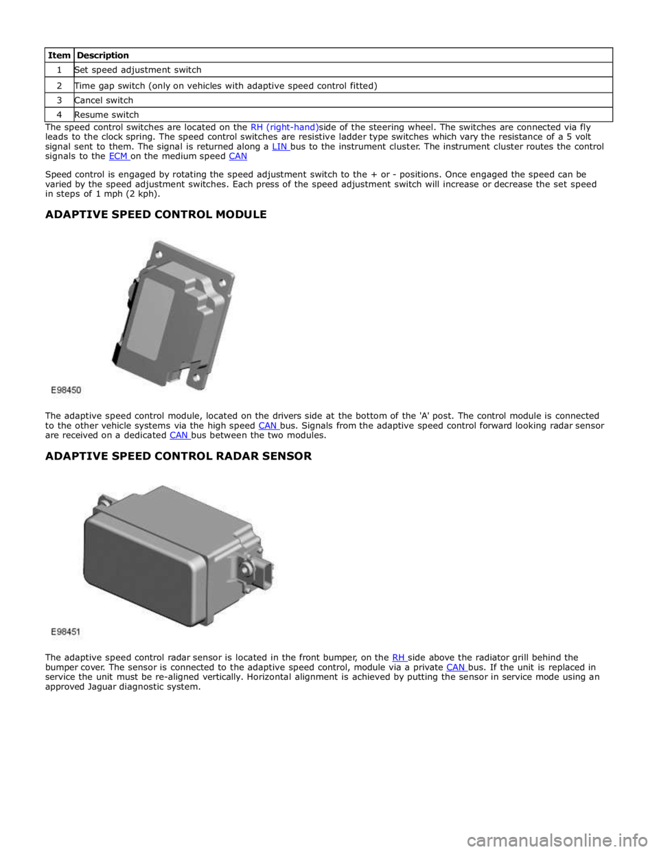
The adaptive speed control module, located on the drivers side at the bottom of the 'A' post. The control module is connected
to the other vehicle systems via the high speed CAN bus. Signals from the adaptive speed control forward looking radar sensor are received on a dedicated CAN bus between the two modules.
ADAPTIVE SPEED CONTROL RADAR SENSOR
The adaptive speed control radar sensor is located in the front bumper, on the RH side above the radiator grill behind the bumper cover. The sensor is connected to the adaptive speed control, module via a private CAN bus. If the unit is replaced in service the unit must be re-aligned vertically. Horizontal alignment is achieved by putting the sensor in service mode using an
approved Jaguar diagnostic system.
Page 1694 of 3039
inlet duct downstream of the blower, where any heat generated during operation is dissipated by the air flow.
Auxiliary Coolant Pump
On all vehicles except 3.0L, an auxiliary coolant pump is installed on the rear right side of the radiator housing, in the return
line from the heater core. The auxiliary coolant pump is an electric pump that boosts the flow of coolant through the heater
core.
Ventilation Outlets
The ventilation outlets allow the free flow of air through the passenger compartment. The outlets are installed in the LH and
RH rear quarter panels, below the rear lamps. Each ventilation outlet consists of a grille covered by a soft rubber flap, and is
effectively a non-return valve. The flaps open and close automatically depending on the pressure differential between the air
inside and outside the vehicle.
Page 1701 of 3039

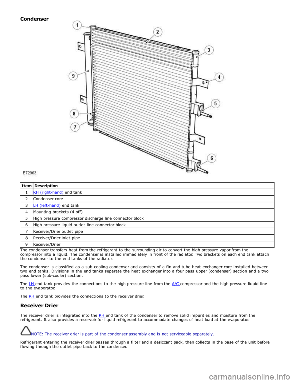
Item Description 1 RH (right-hand) end tank 2 Condenser core 3 LH (left-hand) end tank 4 Mounting brackets (4 off) 5 High pressure compressor discharge line connector block 6 High pressure liquid outlet line connector block 7 Receiver/Drier outlet pipe 8 Receiver/Drier inlet pipe 9 Receiver/Drier The condenser transfers heat from the refrigerant to the surrounding air to convert the high pressure vapor from the
compressor into a liquid. The condenser is installed immediately in front of the radiator. Two brackets on each end tank attach
the condenser to the end tanks of the radiator.
The condenser is classified as a sub-cooling condenser and consists of a fin and tube heat exchanger core installed between
two end tanks. Divisions in the end tanks separate the heat exchanger into a four pass upper (condenser) section and a two
pass lower (sub-cooler) section.
The LH end tank provides the connections to the high pressure line from the A/C compressor and the high pressure liquid line to the evaporator.
The RH end tank provides the connections to the receiver drier.
Receiver Drier
The receiver drier is integrated into the RH end tank of the condenser to remove solid impurities and moisture from the refrigerant. It also provides a reservoir for liquid refrigerant to accommodate changes of heat load at the evaporator.
NOTE: The receiver drier is part of the condenser assembly and is not serviceable separately.
Refrigerant entering the receiver drier passes through a filter and a desiccant pack, then collects in the base of the unit before
flowing through the outlet pipe back to the condenser. Condenser
Page 1762 of 3039
Published: 11-May-2011
Climate Control - Desiccant Bag V6 3.0L Petrol/V8 5.0L Petrol/V8 S/C 5.0L
Petrol
Removal and Installation
Removal
NOTE: Removal steps in this procedure may contain installation details.
1. WARNING: Make sure to support the vehicle with axle stands.
Raise and support the vehicle.
2. Refer to: Air Conditioning (A/C) System Recovery, Evacuation and Charging (412-00 Climate Control System - General Information, General Procedures).
3. Refer to: Radiator Splash Shield (501-02 Front End Body Panels, Removal and Installation).
4. www.JagDocs.com
Page 1777 of 3039
Air Conditioning - Condenser Core V8 S/C 5.0L Petrol
Removal and Installation
Removal
NOTE: Removal steps in this procedure may contain installation details. Published: 11-May-2011
1. Refer to: Air Conditioning (A/C) System Recovery, Evacuation and Charging (412-00 Climate Control System - General Information, General Procedures).
2. WARNING: Do not work on or under a vehicle supported only by a jack.
Always support the vehicle on safety stands.
Raise and support the vehicle.
3. Refer to: Radiator (303-03D Supercharger Cooling - V8 S/C 5.0L Petrol, Removal and Installation).
4. NOTE: Some variation in the illustrations may occur, but
the essential information is always correct. www.JagDocs.com
Page 2202 of 3039
Front End Body Panels - Radiator Splash Shield Removal and Installation
Removal Published: 11-May-2011
1. WARNING: Make sure to support the vehicle with axle stands.
Raise and support the vehicle.
2. Installation
1. To install, reverse the removal procedure.
Page 2579 of 3039
Radiator splash shield outer retaining bolts 3 - 26 Radiator splash shield inner retaining bolts 7 - 62 Radiator splash shield inner retaining screws 2 - 18 Front bumper cover retaining bolts 2 - 18 Rear bumper cover retaining bolts 7 - 62 Rear bumper retaining bolts 25 18 - www.JagDocs.com