2010 JAGUAR XFR Control module
[x] Cancel search: Control modulePage 1657 of 3039
Published: 11-May-2011
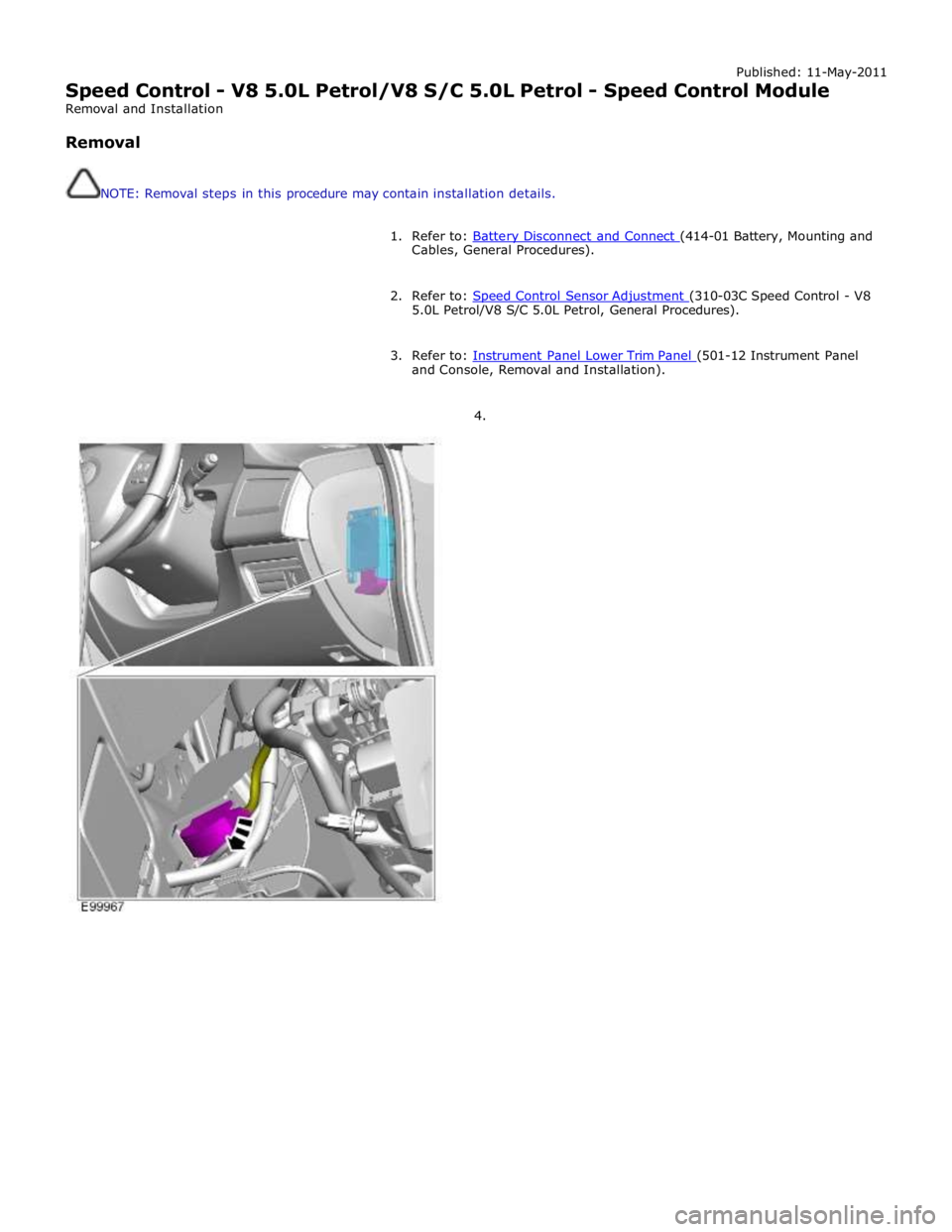
Speed Control - V8 5.0L Petrol/V8 S/C 5.0L Petrol - Speed Control Module
Removal and Installation
Removal
NOTE: Removal steps in this procedure may contain installation details.
1. Refer to: Battery Disconnect and Connect (414-01 Battery, Mounting and Cables, General Procedures).
2. Refer to: Speed Control Sensor Adjustment (310-03C Speed Control - V8 5.0L Petrol/V8 S/C 5.0L Petrol, General Procedures).
3. Refer to: Instrument Panel Lower Trim Panel (501-12 Instrument Panel and Console, Removal and Installation).
4.
Page 1661 of 3039
Published: 11-May-2011
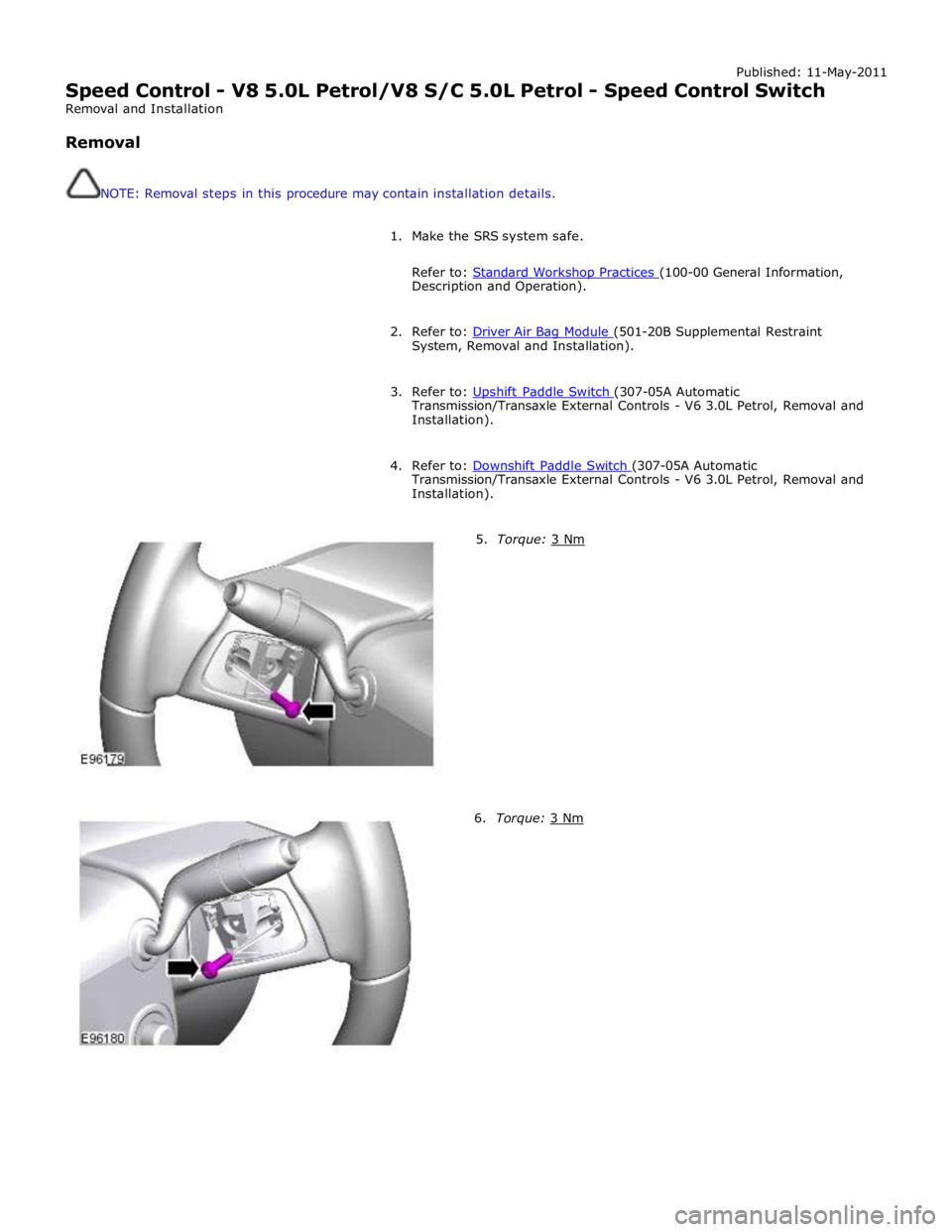
Speed Control - V8 5.0L Petrol/V8 S/C 5.0L Petrol - Speed Control Switch
Removal and Installation
Removal
NOTE: Removal steps in this procedure may contain installation details.
1. Make the SRS system safe.
Refer to: Standard Workshop Practices (100-00 General Information, Description and Operation).
2. Refer to: Driver Air Bag Module (501-20B Supplemental Restraint System, Removal and Installation).
3. Refer to: Upshift Paddle Switch (307-05A Automatic Transmission/Transaxle External Controls - V6 3.0L Petrol, Removal and
Installation).
4. Refer to: Downshift Paddle Switch (307-05A Automatic Transmission/Transaxle External Controls - V6 3.0L Petrol, Removal and
Installation).
5. Torque: 3 Nm 6. Torque: 3 Nm
Page 1664 of 3039
Published: 11-Jul-2014
Climate Control System - General Information - Climate Control System
Diagnosis and Testing
Principles of Operation
For a detailed description of the Climate Control System, refer to the relevant Description and Operation sections in the
Workshop Manual. REFER to:
Air Distribution and Filtering (412-01 Climate Control, Description and Operation), Air Distribution and Filtering (412-01 Climate Control, Description and Operation), Air Distribution and Filtering (412-01 Climate Control, Description and Operation), Heating and Ventilation (412-01 Climate Control, Description and Operation), Heating and Ventilation (412-01 Climate Control, Description and Operation), Heating and Ventilation (412-01 Climate Control, Description and Operation), Air Conditioning (412-01 Climate Control, Description and Operation), Air Conditioning (412-01 Climate Control, Description and Operation), Air Conditioning (412-01 Climate Control, Description and Operation), Control Components (412-01 Climate Control, Description and Operation), Control Components (412-01 Climate Control, Description and Operation), Control Components (412-01 Climate Control, Description and Operation), Electric Booster Heater (412-02 Auxiliary Climate Control, Description and Operation), Electric Booster Heater (412-02 Auxiliary Climate Control, Description and Operation), Electric Booster Heater (412-02 Auxiliary Climate Control, Description and Operation).
Inspection and Verification
WARNING: Servicing must be carried out by personnel familiar with both vehicle system and the charging and testing
equipment. All operations must be carried out in a well ventilated area away from open flame and heat sources.
CAUTION: Diagnosis by substitution from a donor vehicle is NOT acceptable. Substitution of control modules does not
guarantee confirmation of a fault, and may also cause additional faults in the vehicle being tested and/or the donor vehicle.
NOTE: Check and rectify basic faults before beginning diagnostic routines involving pinpoint tests.
1. Verify the customer concern
2. Visually inspect for obvious signs of damage and system integrity
Visual Inspection
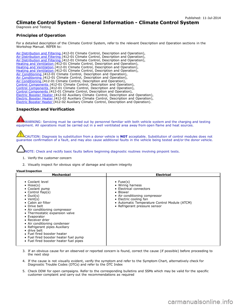
Mechanical Electrical
Coolant level
Hose(s)
Coolant pump
Control flap(s)
Duct(s)
Vent(s)
Cabin air filter
Drive belt
Air conditioning compressor
Thermostatic expansion valve
Evaporator
Receiver drier
Air conditioning condenser
Refrigerant pipes Auxiliary
drive belt
Fuel fired booster heater
Fuel fired booster heater fuel pump
Fuel fired booster heater fuel pipes
Fuse(s)
Wiring harness
Electrical connectors
Blower
Air conditioning compressor
Electric cooling fan
Automatic Temperature Control Module (ATCM)
Refrigerant pressure sensor
3. If an obvious cause for an observed or reported concern is found, correct the cause (if possible) before proceeding to
the next step
4. If the cause is not visually evident, verify the symptom and refer to the Symptom Chart, alternatively check for
Diagnostic Trouble Codes (DTCs) and refer to the DTC Index
5. Check DDW for open campaigns. Refer to the corresponding bulletins and SSMs which may be valid for the specific
customer complaint and carry out the recommendations as required
Page 1666 of 3039
TEST
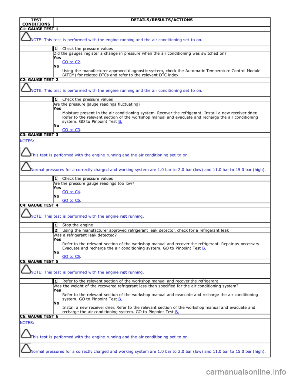
CONDITIONS DETAILS/RESULTS/ACTIONS C1: GAUGE TEST 1
NOTE: This test is performed with the engine running and the air conditioning set to on. 1 Check the pressure values Did the gauges register a change in pressure when the air conditioning was switched on? Yes
GO to C2. No
Using the manufacturer approved diagnostic system, check the Automatic Temperature Control Module (ATCM) for related DTCs and refer to the relevant DTC index C2: GAUGE TEST 2
NOTE: This test is performed with the engine running and the air conditioning set to on. 1 Check the pressure values Are the pressure gauge readings fluctuating? Yes
Moisture present in the air conditioning system. Recover the refrigerant. Install a new receiver drier.
Refer to the relevant section of the workshop manual and evacuate and recharge the air conditioning
system. GO to Pinpoint Test B. No
GO to C3. C3: GAUGE TEST 3 NOTES:
This test is performed with the engine running and the air conditioning set to on.
Normal pressures for a correctly charged and working system are 1.0 bar to 2.0 bar (low) and 11.0 bar to 15.0 bar (high). 1 Check the pressure values Are the pressure gauge readings too low? Yes
GO to C4. No
GO to C6. C4: GAUGE TEST 4
NOTE: This test is performed with the engine not running. 1 Stop the engine 2 Using the manufacturer approved refrigerant leak detector, check for a refrigerant leak Was a refrigerant leak detected? Yes
Refer to the relevant section of the workshop manual and recover the refrigerant. Repair as necessary.
Evacuate and recharge the air conditioning system. GO to Pinpoint Test B. No
GO to C5. C5: GAUGE TEST 5
NOTE: This test is performed with the engine not running. 1 Refer to the relevant section of the workshop manual and recover the refrigerant Was the weight of the recovered refrigerant less than specified for the air conditioning system? Yes
Refer to the relevant section of the workshop manual and evacuate and recharge the air conditioning
system. GO to Pinpoint Test B. No
Install a new receiver drier. Refer to the relevant section of the workshop manual and evacuate and recharge the air conditioning system. GO to Pinpoint Test B. C6: GAUGE TEST 6 NOTES:
This test is performed with the engine running and the air conditioning set to on.
Normal pressures for a correctly charged and working system are 1.0 bar to 2.0 bar (low) and 11.0 bar to 15.0 bar (high).
Page 1667 of 3039
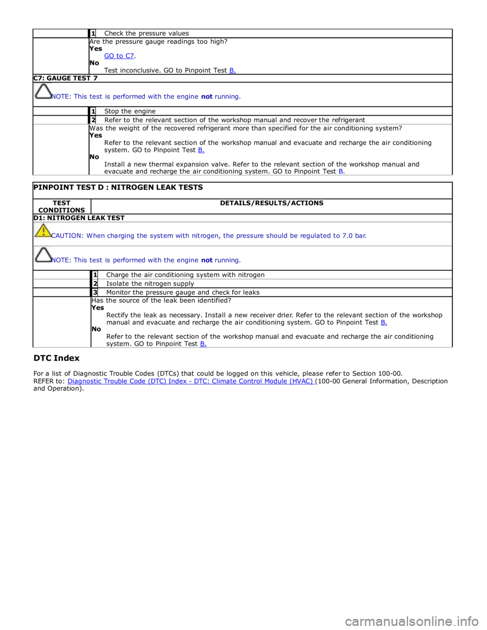
1 Check the pressure values Are the pressure gauge readings too high? Yes
GO to C7. No
Test inconclusive. GO to Pinpoint Test B. C7: GAUGE TEST 7
NOTE: This test is performed with the engine not running. 1 Stop the engine 2 Refer to the relevant section of the workshop manual and recover the refrigerant Was the weight of the recovered refrigerant more than specified for the air conditioning system? Yes
Refer to the relevant section of the workshop manual and evacuate and recharge the air conditioning
system. GO to Pinpoint Test B. No
Install a new thermal expansion valve. Refer to the relevant section of the workshop manual and
evacuate and recharge the air conditioning system. GO to Pinpoint Test B.
PINPOINT TEST D : NITROGEN LEAK TESTS TEST
CONDITIONS DETAILS/RESULTS/ACTIONS D1: NITROGEN LEAK TEST
CAUTION: When charging the system with nitrogen, the pressure should be regulated to 7.0 bar.
NOTE: This test is performed with the engine not running. 1 Charge the air conditioning system with nitrogen 2 Isolate the nitrogen supply 3 Monitor the pressure gauge and check for leaks Has the source of the leak been identified?
Yes
Rectify the leak as necessary. Install a new receiver drier. Refer to the relevant section of the workshop
manual and evacuate and recharge the air conditioning system. GO to Pinpoint Test B. No
Refer to the relevant section of the workshop manual and evacuate and recharge the air conditioning system. GO to Pinpoint Test B.
DTC Index
For a list of Diagnostic Trouble Codes (DTCs) that could be logged on this vehicle, please refer to Section 100-00.
REFER to: Diagnostic Trouble Code (DTC) Index - DTC: Climate Control Module (HVAC) (100-00 General Information, Description and Operation).
Page 1682 of 3039

Blower motor control module retaining bolts 1 - 9 Foot duct to cross car beam retaining bolt 5 - 44 Climate control assembly to cross car beam retaining bolts 9 - 80 Climate control module retaining bolts 1 - 9 Defrost vent/register blend door actuator retaining bolts 1 - 9 Evaporator pipe bracket retaining bolts 1 - 9 Evaporator housing retaining bolts 1 - 9 Footwell vent/duct blend door actuator retaining bolt 1 - 9 Heater core housing retaining bolts 2 - 18 Sunload sensor retaining bolt 2 - 18 Evaporator core pipes mounting bracket retaining bolts 1 - 9 Evaporator core pipes to thermostatic expansion valve retaining bolt 5 - 44 Thermostatic expansion valve retaining bolts 3 - 26 www.JagDocs.com
Page 1686 of 3039
Published: 11-May-2011
Climate Control - Air Distribution and Filtering - System Operation and
Component Description
Description and Operation
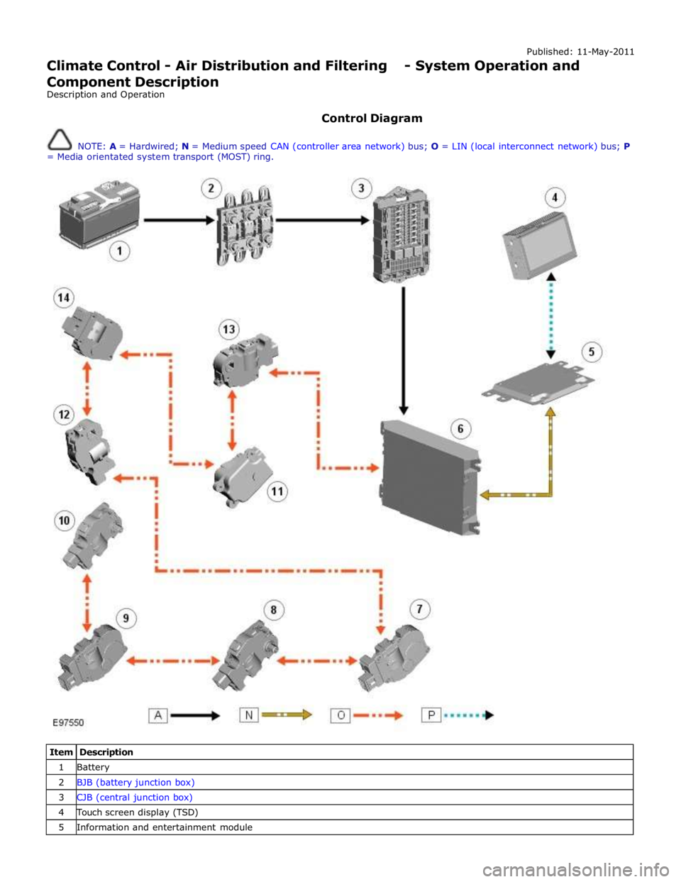
Control Diagram
NOTE: A = Hardwired; N = Medium speed CAN (controller area network) bus; O = LIN (local interconnect network) bus; P
= Media orientated system transport (MOST) ring.
Item Description 1 Battery 2 BJB (battery junction box) 3 CJB (central junction box) 4 Touch screen display (TSD) 5 Information and entertainment module
Page 1687 of 3039
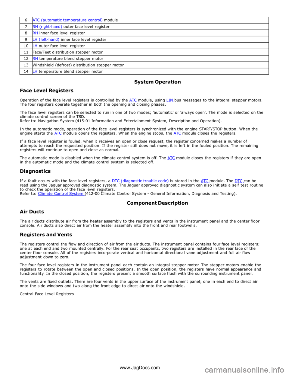
7 RH (right-hand) outer face level register 8 RH inner face level register 9 LH (left-hand) inner face level register 10 LH outer face level register 11 Face/Feet distribution stepper motor 12 RH temperature blend stepper motor 13 Windshield (defrost) distribution stepper motor 14 LH temperature blend stepper motor
Face Level Registers System Operation
Operation of the face level registers is controlled by the ATC module, using LIN bus messages to the integral stepper motors. The four registers operate together in both the opening and closing phases.
The face level registers can be selected to run in one of two modes; 'automatic' or 'always open'. The mode is selected on the
climate control screen of the TSD.
Refer to: Navigation System (415-01 Information and Entertainment System, Description and Operation).
In the automatic mode, operation of the face level registers is synchronized with the engine START/STOP button. When the
engine starts the ATC module opens the registers. When the engine stops, the ATC module closes the registers.
If a face level register is fouled, when it receives an open or close request, the register concerned makes a number of
attempts to reach the requested position. If the register still does not move, it is left in the fouled position. The remaining
registers will continue to open and close as normal.
The automatic mode is disabled when the climate control system is off. The ATC module closes the registers if they are open in the automatic mode and the climate control system is selected off.
Diagnostics
If a fault occurs with the face level registers, a DTC (diagnostic trouble code) is stored in the ATC module. The DTC can be read using the Jaguar approved diagnostic system. The Jaguar approved diagnostic system can also initiate a self test routine
to check the operation of the face level registers.
Refer to: Climate Control System (412-00 Climate Control System - General Information, Diagnosis and Testing).
Air Ducts Component Description
The air ducts distribute air from the heater assembly to the registers and vents in the instrument panel and the center floor
console. Air ducts also direct air from the heater assembly into the front and rear footwells.
Registers and Vents
The registers control the flow and direction of air from the air ducts. The instrument panel contains four face level registers;
one at each end and two mounted centrally. For the rear seat occupants, two registers are installed in the rear face of the
center floor console. All of the registers incorporate vertical and horizontal directional vane adjustment and full air flow
adjustment down to zero.
The four face level registers in the instrument panel each contain an integral stepper motor. The stepper motors enable the
registers to rotate between the open and closed positions. In the open position, the registers have normal appearance and
functionality. In the closed position, the registers present a smooth surface flush with the surrounding instrument panel.
The vents are fixed outlets. There are four vents in the upper surface of the instrument panel; one in each end to direct air
onto the side windows and two along the front edge to direct air onto the windshield.
Central Face Level Registers
www.JagDocs.com