Page 554 of 3039
Rear Drive Axle/Differential - Differential Locking Motor
Removal and Installation
Removal
NOTE: Removal steps in this procedure may contain installation details. Published: 26-Feb-2014
1. Refer to: Differential Draining and Filling (205-02 Rear Drive Axle/Differential, General Procedures).
2.
3.
Page 563 of 3039
Published: 11-May-2011
Rear Drive Halfshafts - Rear Drive Halfshafts - System Operation and
Component Description
Description and Operation
System Operation
Rear Drive Halfshafts Component Description
The solid-steel halfshafts are of unequal length, with each halfshaft comprising inner and outer CV (constant velocity) joints.
The CV joints are the 'ball and socket' type packed with grease and protected by gaiters.
The outer CV joint is an interference fit into the wheel hub and secured by a locking nut. The inner CV joint is a slide fit and is
retained in the differential with a spring clip.
www.JagDocs.com
Page 574 of 3039
15.
16. CAUTION: Do not use air tools to install the nut.
Failure to follow this instruction may result in damage to
the component.
Torque: 300 Nm
Check and top-up the differential case.
17.
Install the LH rear wheel and tire.
Refer to: Wheel and Tire (204-04 Wheels and Tires, Removal and Installation).
Page 664 of 3039
Parking Brake and Actuation - Parking Brake Release Actuator
Removal and Installation
Removal Published: 06-May-2014
WARNING: Failure to release the tension and calibrate the electric parking brake during rear parking brake related service
procedures, could cause the parking brake to function incorrectly or become inoperative.
1. Refer to: Parking Brake Cable Tension Release (206-05 Parking Brake and Actuation, General Procedures).
2. WARNING: Make sure to support the vehicle with axle stands.
Raise and support the vehicle.
3. Remove the differential case.
Refer to: Differential Case - TDV6 3.0L Diesel /V8 5.0L Petrol/V8 S/C 5.0L Petrol (205-02 Rear Drive Axle/Differential, Removal and Installation).
Refer to: Differential Case - TD4 2.2L Diesel/TDV6 3.0L Diesel (205-02,
Removal and Installation).
4. Torque: 7 Nm
Page 1350 of 3039
Published: 11-May-2011
Evaporative Emissions - V8 5.0L Petrol/V8 S/C 5.0L Petrol - Evaporative
Emission Canister
Removal and Installation
Removal
NOTE: Removal steps in this procedure may contain installation details.
1. Refer to: Petrol and Petrol-Ethanol Fuel Systems Health and Safety Precautions (100-00 General Information, Description and Operation).
2. WARNING: Do not work on or under a vehicle supported only by a jack.
Always support the vehicle on safety stands.
Raise and support the vehicle.
3. Refer to: Differential Case - TDV6 3.0L Diesel /V8 5.0L Petrol/V8 S/C 5.0L Petrol (205-02 Rear Drive Axle/Differential, Removal and Installation).
Installation
4.
5. Torque: 9 Nm
1. To install, reverse the removal procedure. www.JagDocs.com
Page 1694 of 3039
inlet duct downstream of the blower, where any heat generated during operation is dissipated by the air flow.
Auxiliary Coolant Pump
On all vehicles except 3.0L, an auxiliary coolant pump is installed on the rear right side of the radiator housing, in the return
line from the heater core. The auxiliary coolant pump is an electric pump that boosts the flow of coolant through the heater
core.
Ventilation Outlets
The ventilation outlets allow the free flow of air through the passenger compartment. The outlets are installed in the LH and
RH rear quarter panels, below the rear lamps. Each ventilation outlet consists of a grille covered by a soft rubber flap, and is
effectively a non-return valve. The flaps open and close automatically depending on the pressure differential between the air
inside and outside the vehicle.
Page 1706 of 3039

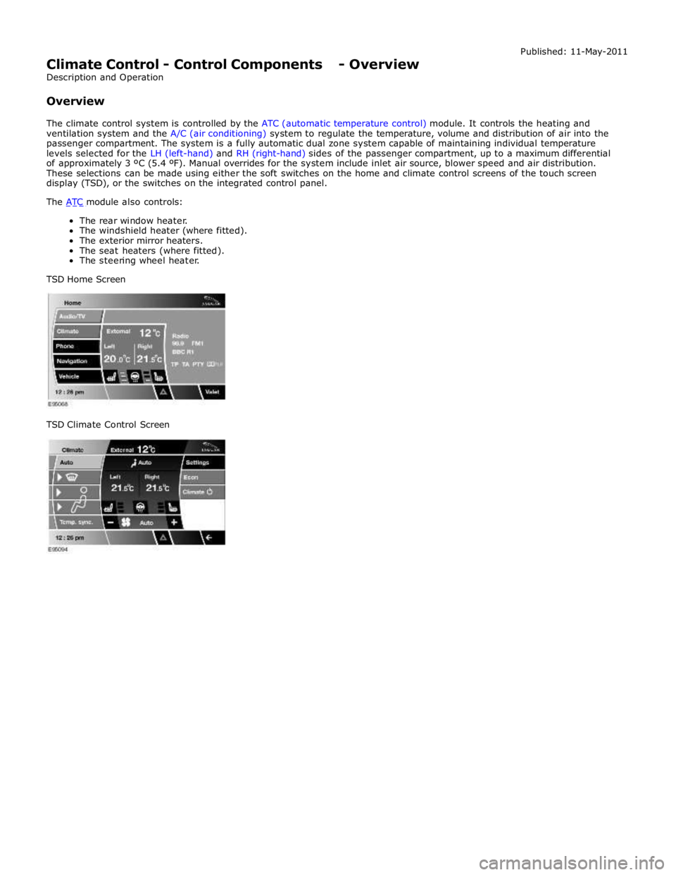
Climate Control - Control Components - Overview
Description and Operation
Overview Published: 11-May-2011
The climate control system is controlled by the ATC (automatic temperature control) module. It controls the heating and
ventilation system and the A/C (air conditioning) system to regulate the temperature, volume and distribution of air into the
passenger compartment. The system is a fully automatic dual zone system capable of maintaining individual temperature
levels selected for the LH (left-hand) and RH (right-hand) sides of the passenger compartment, up to a maximum differential
of approximately 3 ºC (5.4 ºF). Manual overrides for the system include inlet air source, blower speed and air distribution.
These selections can be made using either the soft switches on the home and climate control screens of the touch screen
display (TSD), or the switches on the integrated control panel.
The ATC module also controls: The rear window heater.
The windshield heater (where fitted).
The exterior mirror heaters.
The seat heaters (where fitted).
The steering wheel heater.
TSD Home Screen
TSD Climate Control Screen
Page 1828 of 3039

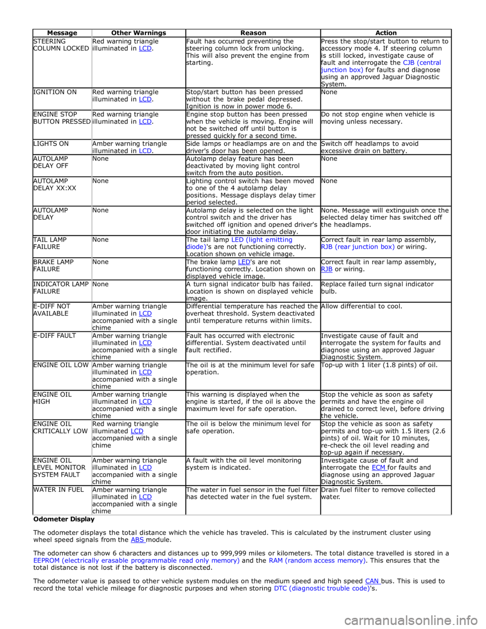
STEERING
COLUMN LOCKED Red warning triangle
illuminated in LCD. Fault has occurred preventing the
steering column lock from unlocking. This will also prevent the engine from
starting. Press the stop/start button to return to
accessory mode 4. If steering column
is still locked, investigate cause of
fault and interrogate the CJB (central junction box) for faults and diagnose
using an approved Jaguar Diagnostic System. IGNITION ON
Red warning triangle
illuminated in LCD. Stop/start button has been pressed
without the brake pedal depressed. Ignition is now in power mode 6. None ENGINE STOP
BUTTON PRESSED Red warning triangle
illuminated in LCD. Engine stop button has been pressed
when the vehicle is moving. Engine will
not be switched off until button is pressed quickly for a second time. Do not stop engine when vehicle is
moving unless necessary. LIGHTS ON
Amber warning triangle
illuminated in LCD. Side lamps or headlamps are on and the
driver's door has been opened. Switch off headlamps to avoid
excessive drain on battery. AUTOLAMP
DELAY OFF None
Autolamp delay feature has been
deactivated by moving light control
switch from the auto position. None AUTOLAMP
DELAY XX:XX None
Lighting control switch has been moved
to one of the 4 autolamp delay
positions. Message displays delay timer period selected. None AUTOLAMP
DELAY None
Autolamp delay is selected on the light
control switch and the driver has
switched off ignition and opened driver's
door initiating the autolamp delay. None. Message will extinguish once the
selected delay timer has switched off
the headlamps. TAIL LAMP
FAILURE None The tail lamp LED (light emitting
diode)'s are not functioning correctly.
Location shown on vehicle image. Correct fault in rear lamp assembly,
RJB (rear junction box) or wiring. BRAKE LAMP
FAILURE None The brake lamp LED's are not functioning correctly. Location shown on displayed vehicle image. Correct fault in rear lamp assembly,
RJB or wiring. INDICATOR LAMP
FAILURE None
A turn signal indicator bulb has failed.
Location is shown on displayed vehicle image. Replace failed turn signal indicator
bulb. E-DIFF NOT
AVAILABLE Amber warning triangle
illuminated in LCD accompanied with a single
chime Differential temperature has reached the
overheat threshold. System deactivated
until temperature returns within limits. Allow differential to cool. E-DIFF FAULT
Amber warning triangle
illuminated in LCD accompanied with a single
chime Fault has occurred with electronic
differential. System deactivated until
fault rectified. Investigate cause of fault and
interrogate the system for faults and
diagnose using an approved Jaguar Diagnostic System. ENGINE OIL LOW
Amber warning triangle
illuminated in LCD accompanied with a single
chime The oil is at the minimum level for safe
operation. Top-up with 1 liter (1.8 pints) of oil. ENGINE OIL
HIGH Amber warning triangle
illuminated in LCD accompanied with a single
chime This warning is displayed when the
engine is started, if the oil is above the
maximum level for safe operation. Stop the vehicle as soon as safety
permits and have the engine oil
drained to correct level, before driving
the vehicle. ENGINE OIL
CRITICALLY LOW Red warning triangle
illuminated LCD accompanied with a single
chime The oil is below the minimum level for
safe operation. Stop the vehicle as soon as safety
permits and top-up with 1.5 liters (2.6
pints) of oil. Wait for 10 minutes,
re-check the oil level reading and top-up again if necessary. ENGINE OIL
LEVEL MONITOR
SYSTEM FAULT Amber warning triangle
illuminated in LCD accompanied with a single
chime A fault with the oil level monitoring
system is indicated. Investigate cause of fault and
interrogate the ECM for faults and diagnose using an approved Jaguar Diagnostic System. WATER IN FUEL
Amber warning triangle
illuminated in LCD accompanied with a single
chime The water in fuel sensor in the fuel filter
has detected water in the fuel system. Drain fuel filter to remove collected
water. Odometer Display
The odometer displays the total distance which the vehicle has traveled. This is calculated by the instrument cluster using
wheel speed signals from the ABS module.
The odometer can show 6 characters and distances up to 999,999 miles or kilometers. The total distance travelled is stored in a
EEPROM (electrically erasable programmable read only memory) and the RAM (random access memory). This ensures that the
total distance is not lost if the battery is disconnected.
The odometer value is passed to other vehicle system modules on the medium speed and high speed CAN bus. This is used to record the total vehicle mileage for diagnostic purposes and when storing DTC (diagnostic trouble code)'s.