2010 JAGUAR XFR warning light
[x] Cancel search: warning lightPage 698 of 3039

center and an amber warning indicator will illuminate.
Refer to: Information and Message Center (413-08 Information and Message Center, Description and Operation).
As the wheel speed sensors are active devices, a return signal is available when the road wheels are not rotating. This enables
the ABS module to check the condition of the speed sensors while the vehicle is stationary.
Steering Angle Sensor
The steering angle sensor measures the steering wheel angle and the rate of change of the steering wheel angle. These
measurements are received by the ABS module and broadcast on the high speed CAN bus for use by other systems.
The steering angle sensor is mounted on the steering column upper shroud mounting bracket, immediately behind the
multifunction switches, and is secured by 2 screws. A fly lead connects the sensor to the passenger compartment wiring
harness via a 4 pin multiplug.
The sensor is housed in a 'U' shaped plastic casing and contains two offset LED (light emitting diode)s facing two detectors.
An encoder ring is mounted on the inner steering column shaft and intersects the LEDs and detectors. The encoder ring contains 60 slots which break and restore the light beams between the LEDs and the detectors as the steering wheel is
Page 703 of 3039

Published: 09-Jul-2014
Anti-Lock Control - Stability Assist - Anti-Lock Control - Stability Assist
Diagnosis and Testing
Principle of Operation
For a detailed description of the Anti-Lock Control - Stability Assist system, refer to the relevant Description and Operation
sections in the workshop manual. REFER to: (206-09 Anti-Lock Control - Stability Assist)
Anti-Lock Control - Stability Assist (Description and Operation), Anti-Lock Control - Stability Assist (Description and Operation), Anti-Lock Control - Stability Assist (Description and Operation).
Inspection and Verification
CAUTION: Diagnosis by substitution from a donor vehicle is NOT acceptable. Substitution of control modules does not
guarantee confirmation of a fault, and may also cause additional faults in the vehicle being tested and/or the donor vehicle.
1. Verify the customer concern.
2. Confirm if the Anti-Lock Brake System (ABS) warning light was illuminated, or still is.
NOTE: An intermittent fault may allow the warning light to go off. This does not necessarily mean the fault is not
present. Some warnings will appear to clear when the ignition is cycled. This is often because the warning has flagged as a
result of one of the vehicle's on-board diagnostic routines having run to detect the fault. If the same routine is not run when
the ignition status is set to ON, the warning will not re-flag until the routine does run.
3. Visually inspect for obvious signs of damage and system integrity.
Visual Inspection
Mechanical Electrical
Brake fluid level
Vacuum system
Wheel speed sensor installation
Wheel speed sensor air gap
Magnetic pulse wheel(s) (damaged/contaminated)
Steering angle sensor
Yaw rate sensor and accelerometer cluster installation
Incorrect wheel or tire size
Warning light operation
Fuses
Wheel speed sensors
Connectors/Pins
Harnesses
Steering wheel rotation sensor
Yaw rate sensor and accelerometer cluster
Booster pressure sensor
Hydraulic Control Unit (HCU)
4. If an obvious cause for an observed or reported concern is found, correct the cause (if possible) before proceeding to
the next step.
5. If the cause is not visually evident check for Diagnostic Trouble Codes (DTCs) and refer to the DTC Index.
DTC Index
For a list of Diagnostic Trouble Codes (DTCs) that could be logged on this vehicle, please refer to Section 100-00.
REFER to: Diagnostic Trouble Code (DTC) Index - DTC: Anti-Lock Braking System (ABS) (100-00 General Information, Description and Operation).
Page 1177 of 3039
Fuel Charging and Controls - V8 S/C 5.0L Petrol -
WARNINGS: Published: 11-May-2011
Do not smoke or carry lighted tobacco or open flame of any type when working on or near any fuel related components.
Highly flammable vapors are always present and may ignite. Failure to follow these instructions may result in personal injury.
Before any work is carried out on the fuel system, ground the vehicle to earth and maintain the ground connection until
the work is complete.
CAUTION: Before disconnecting or removing components, make sure the area around the joint faces and connections are
clean. Plug open connections to prevent contamination.
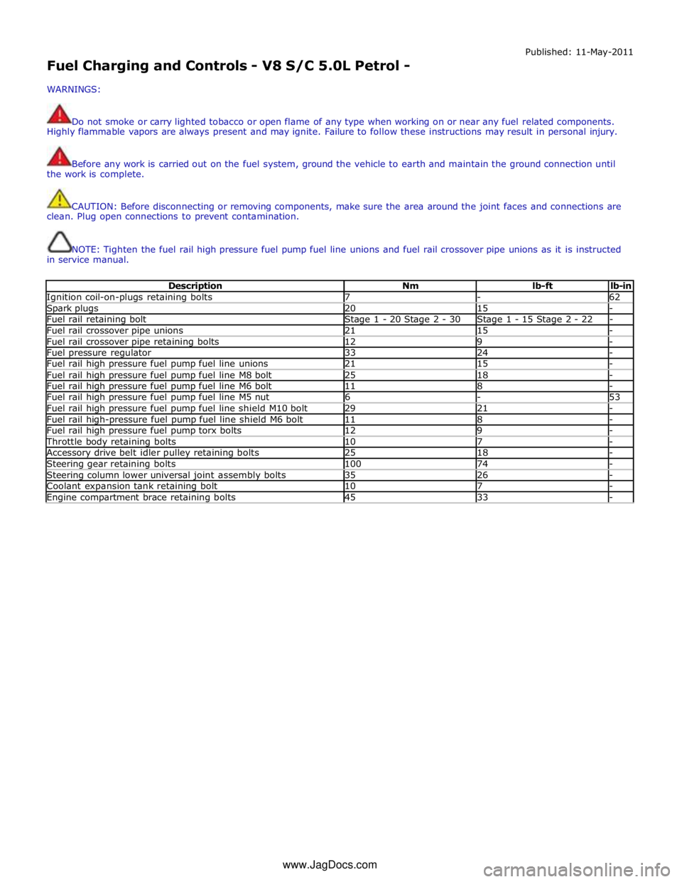
NOTE: Tighten the fuel rail high pressure fuel pump fuel line unions and fuel rail crossover pipe unions as it is instructed
in service manual.
Description Nm lb-ft lb-in Ignition coil-on-plugs retaining bolts 7 - 62 Spark plugs 20 15 - Fuel rail retaining bolt Stage 1 - 20 Stage 2 - 30 Stage 1 - 15 Stage 2 - 22 - Fuel rail crossover pipe unions 21 15 - Fuel rail crossover pipe retaining bolts 12 9 - Fuel pressure regulator 33 24 - Fuel rail high pressure fuel pump fuel line unions 21 15 - Fuel rail high pressure fuel pump fuel line M8 bolt 25 18 - Fuel rail high pressure fuel pump fuel line M6 bolt 11 8 - Fuel rail high pressure fuel pump fuel line M5 nut 6 - 53 Fuel rail high pressure fuel pump fuel line shield M10 bolt 29 21 - Fuel rail high-pressure fuel pump fuel line shield M6 bolt 11 8 - Fuel rail high pressure fuel pump torx bolts 12 9 - Throttle body retaining bolts 10 7 - Accessory drive belt idler pulley retaining bolts 25 18 - Steering gear retaining bolts 100 74 - Steering column lower universal joint assembly bolts 35 26 - Coolant expansion tank retaining bolt 10 7 - Engine compartment brace retaining bolts 45 33 - www.JagDocs.com
Page 1189 of 3039
Published: 11-May-2011
Fuel Charging and Controls - V8 S/C 5.0L Petrol - Fuel Injection Component Cleaning
General Procedures
General Equipment
WARNINGS: Cleaning
Do not carry out any repairs to the fuel system with the engine running. Failure to follow this instruction may result in
personal injury.
Do not smoke or carry lighted tobacco or open flame of any type when working on or near any fuel related components.
Highly flammable vapors are always present and may ignite. Failure to follow these instructions may result in personal injury.
If fuel contacts the eyes, flush the eyes with cold water or eyewash solution and seek immediate medical attention.
Place the vehicle in a well ventilated, quarantined area and arrange ' No Smoking/Petrol Fumes' signs about the vehicle.
Wash hands thoroughly after fuel handling, as prolonged contact may cause irritation. Should irritation develop, seek
medical attention.
Do not carry or operate cellular phones when working on or near any fuel related components. Highly flammable vapors
are always present and may ignite. Failure to follow these instructions may result in personal injury.
CAUTIONS:
Before using the cleaning fluid, protect all electrical components and connectors with lint-free non-flocking material.
Make sure that all parts removed from the vehicle are placed on the lint-free non-flocking material.
Make sure that any protective clothing worn is clean and made from lint-free non-flocking material.
Make sure that clean non-plated tools are used. Clean tools using a new brush that will not lose its bristles, prior to
starting work on the vehicle.
Use a steel topped workbench and cover it with clean, lint-free non-flocking material.
Make sure the workshop area in which the vehicle is being worked on is as clean and as dust free as possible. Foreign
matter from work on clutches, brakes or from machining or welding operations can contaminate the fuel system and may result
in later malfunction.
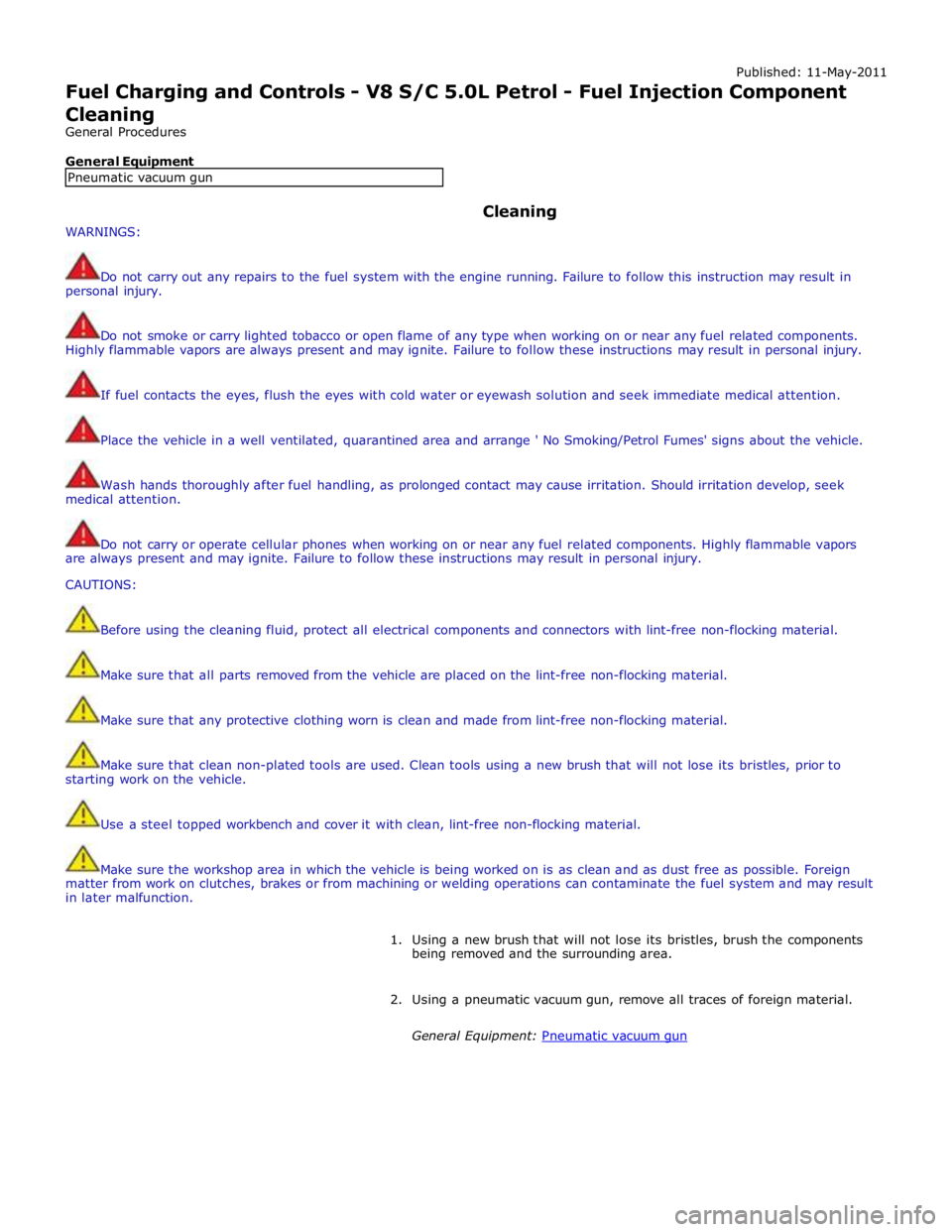
1. Using a new brush that will not lose its bristles, brush the components
being removed and the surrounding area.
2. Using a pneumatic vacuum gun, remove all traces of foreign material.
General Equipment: Pneumatic vacuum gun Pneumatic vacuum gun
Page 1314 of 3039
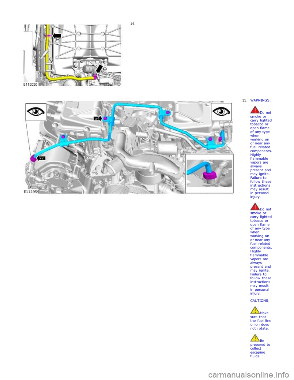
14.
15.
WARNINGS:
Do not
smoke or
carry lighted
tobacco or
open flame
of any type
when
working on
or near any
fuel related
components.
Highly
flammable
vapors are
always
present and
may ignite.
Failure to
follow these
instructions
may result
in personal
injury.
Do not
smoke or
carry lighted
tobacco or
open flame
of any type
when
working on
or near any
fuel related
components.
Highly
flammable
vapors are
always
present and
may ignite.
Failure to
follow these
instructions
may result
in personal
injury.
CAUTIONS:
Make
sure that
the fuel line
union does
not rotate.
Be
prepared to
collect
escaping
fluids.
Page 1317 of 3039
Installation
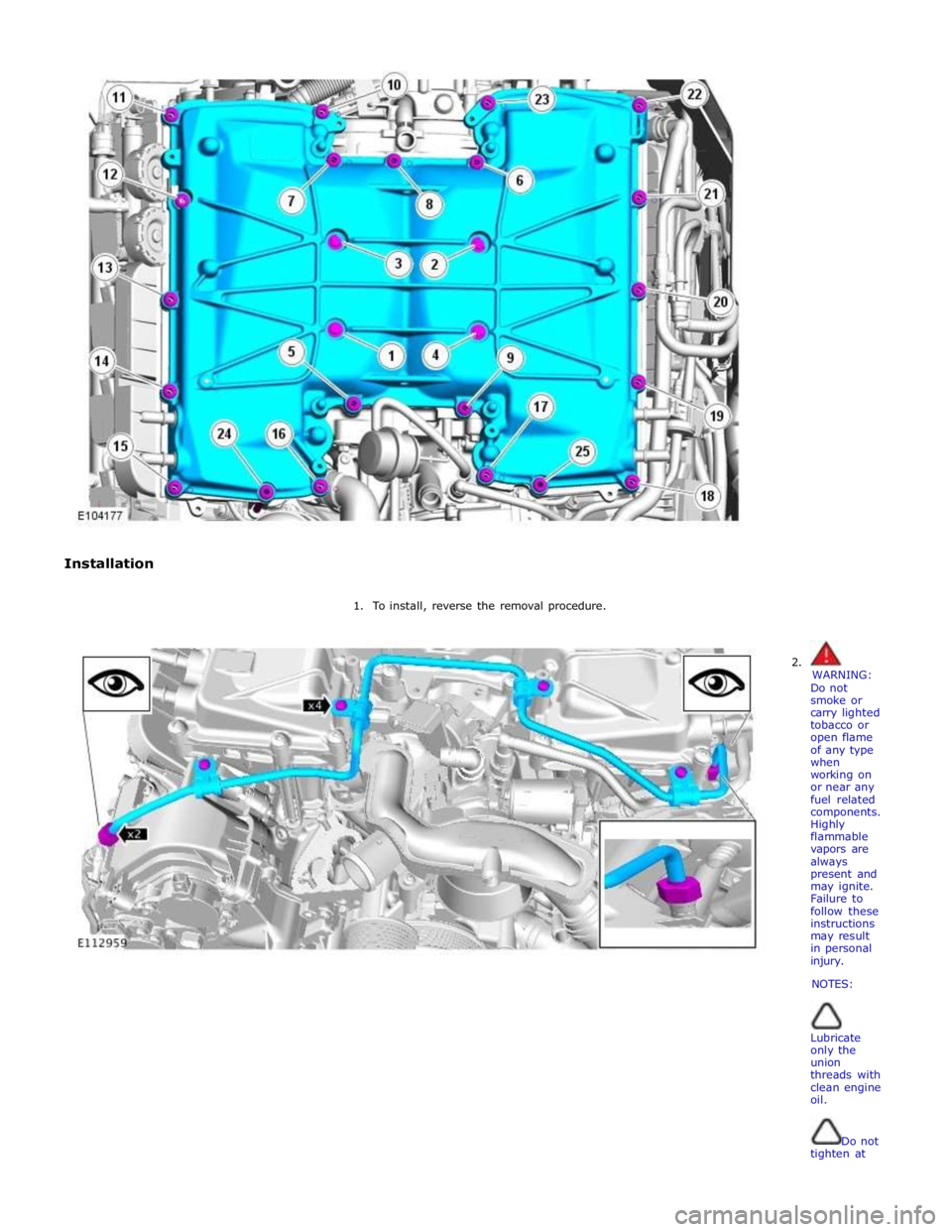
1. To install, reverse the removal procedure.
2.
WARNING:
Do not
smoke or
carry lighted
tobacco or
open flame
of any type
when
working on
or near any
fuel related
components.
Highly
flammable
vapors are
always
present and
may ignite.
Failure to
follow these
instructions
may result
in personal
injury.
NOTES:
Lubricate
only the
union
threads with
clean engine
oil.
Do not
tighten at
Page 1318 of 3039
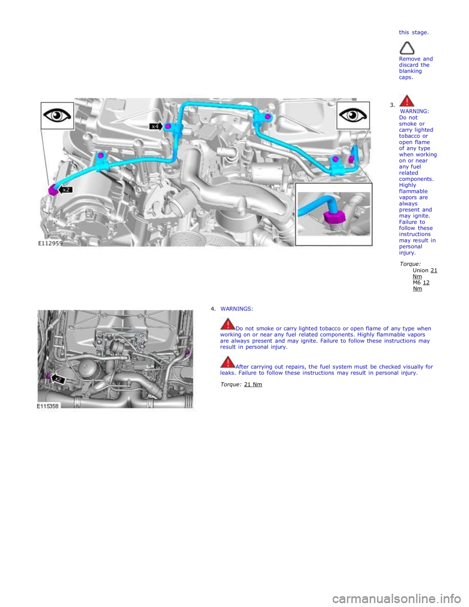
this stage.
Remove and
discard the
blanking
caps.
3.
WARNING:
Do not
smoke or
carry lighted
tobacco or
open flame
of any type
when working
on or near
any fuel
related
components.
Highly
flammable
vapors are
always
present and
may ignite.
Failure to
follow these
instructions
may result in
personal
injury.
Torque:
Union 21 Nm M6 12 Nm
4. WARNINGS:
Do not smoke or carry lighted tobacco or open flame of any type when
working on or near any fuel related components. Highly flammable vapors
are always present and may ignite. Failure to follow these instructions may
result in personal injury.
After carrying out repairs, the fuel system must be checked visually for
leaks. Failure to follow these instructions may result in personal injury.
Torque: 21 Nm
Page 1372 of 3039
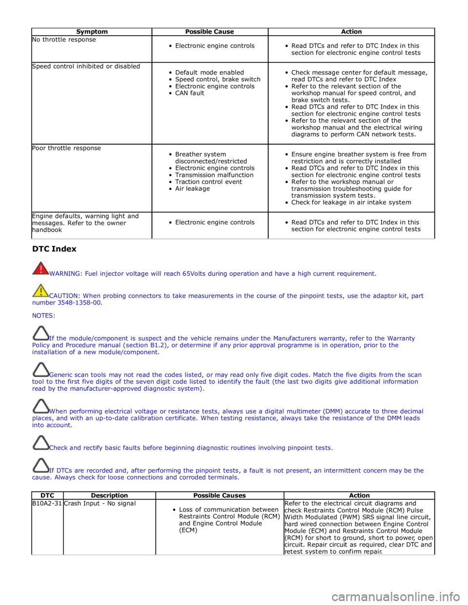
Symptom Possible Cause Action No throttle response
Electronic engine controls
Read DTCs and refer to DTC Index in this
section for electronic engine control tests Speed control inhibited or disabled
Default mode enabled
Speed control, brake switch
Electronic engine controls
CAN fault
Check message center for default message,
read DTCs and refer to DTC Index
Refer to the relevant section of the
workshop manual for speed control, and
brake switch tests.
Read DTCs and refer to DTC Index in this
section for electronic engine control tests
Refer to the relevant section of the
workshop manual and the electrical wiring
diagrams to perform CAN network tests. Poor throttle response
Breather system
disconnected/restricted
Electronic engine controls
Transmission malfunction
Traction control event
Air leakage
Ensure engine breather system is free from
restriction and is correctly installed
Read DTCs and refer to DTC Index in this
section for electronic engine control tests
Refer to the workshop manual or
transmission troubleshooting guide for
transmission system tests.
Check for leakage in air intake system Engine defaults, warning light and
messages. Refer to the owner
handbook
Electronic engine controls
Read DTCs and refer to DTC Index in this
section for electronic engine control tests DTC Index
WARNING: Fuel injector voltage will reach 65Volts during operation and have a high current requirement.
CAUTION: When probing connectors to take measurements in the course of the pinpoint tests, use the adaptor kit, part
number 3548-1358-00.
NOTES:
If the module/component is suspect and the vehicle remains under the Manufacturers warranty, refer to the Warranty
Policy and Procedure manual (section B1.2), or determine if any prior approval programme is in operation, prior to the
installation of a new module/component.
Generic scan tools may not read the codes listed, or may read only five digit codes. Match the five digits from the scan
tool to the first five digits of the seven digit code listed to identify the fault (the last two digits give additional information
read by the manufacturer-approved diagnostic system).
When performing electrical voltage or resistance tests, always use a digital multimeter (DMM) accurate to three decimal
places, and with an up-to-date calibration certificate. When testing resistance, always take the resistance of the DMM leads
into account.
Check and rectify basic faults before beginning diagnostic routines involving pinpoint tests.
If DTCs are recorded and, after performing the pinpoint tests, a fault is not present, an intermittent concern may be the
cause. Always check for loose connections and corroded terminals.
DTC Description Possible Causes Action B10A2-31 Crash Input - No signal
Loss of communication between
Restraints Control Module (RCM)
and Engine Control Module
(ECM) Refer to the electrical circuit diagrams and
check Restraints Control Module (RCM) Pulse
Width Modulated (PWM) SRS signal line circuit,
hard wired connection between Engine Control
Module (ECM) and Restraints Control Module
(RCM) for short to ground, short to power, open
circuit. Repair circuit as required, clear DTC and
retest system to confirm repair.