Page 317 of 3039

Published: 16-Oct-2013
Suspension System - General Information - Four-Wheel Alignment
General Procedures
CAUTIONS:
Make sure the vehicle is on a flat level surface.
Make sure the tire pressures are within specification.
Make sure that only the manufacturers' recommended four wheel alignment equipment is used.
Make sure the steering is in the straight ahead position.
1. For wheel alignment information, refer to the suspension specification
section.
For additional information, refer to: Specifications (204-00 Suspension System - General Information, Specifications).
2. Check the tie rod ends, suspension joints, wheel bearings and wheels
and tires for damage, wear and free play.
Adjust or repair any worn, damaged or incorrectly adjusted
components.
3. Check and adjust tire pressures.
4. Position the vehicle on a calibrated, level, vehicle lift.
5. Vehicles with air suspension.
For additional information, refer to: Air Suspension Manual Tight
Tolerance Setting Mode (204-05, General Procedures).
6. Release the vehicle parking brake.
7. Using only four-wheel alignment equipment approved by Jaguar, check
the wheel alignment.
8. NOTE: LH illustration shown, RH is similar. To
adjust, loosen the toe link locknuts. www.JagDocs.com
Page 321 of 3039

Published: 16-Oct-2013
Suspension System - General Information - Front Toe Adjustment
General Procedures
CAUTIONS:
Make sure the vehicle is on a flat level surface.
Make sure the tire pressures are within specification.
Make sure that only the manufacturers' recommended four wheel alignment equipment is used.
Make sure the steering is in the straight ahead position.
1. For wheel alignment information, refer to the suspension specification
section.
For additional information, refer to: Specifications (204-00 Suspension System - General Information, Specifications).
2. Check the tie rod ends, suspension joints, wheel bearings and wheels
and tires for damage, wear and free play.
Adjust or repair any worn, damaged or incorrectly adjusted
components.
3. Check and adjust tire pressures.
4. Position the vehicle on a 4 post lift.
5. Release the vehicle parking brake.
6. Vehicles with air suspension.
For additional information, refer to: Air Suspension Manual Tight
Tolerance Setting Mode (204-05, General Procedures).
7. For additional information, refer to: Air Suspension Manual Tight
Tolerance Setting Mode (204-05, General Procedures).
8. Using only four-wheel alignment equipment approved by Jaguar, check
the wheel alignment.
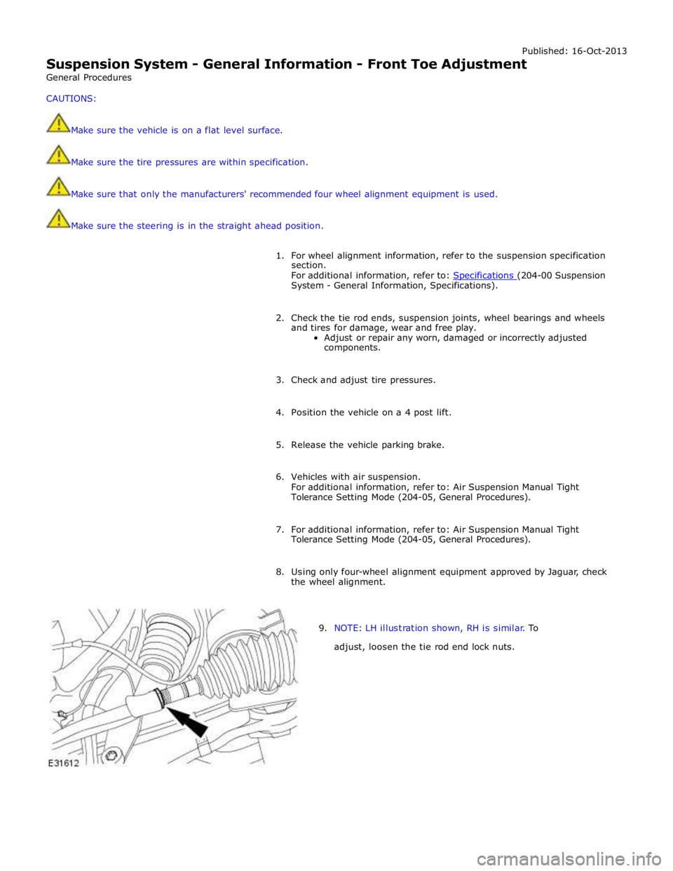
9. NOTE: LH illustration shown, RH is similar. To
adjust, loosen the tie rod end lock nuts.
Page 324 of 3039

Published: 14-Feb-2012
Suspension System - General Information - Front Wheel Bearing and Wheel Hub Runout Check Vehicles With: High Performance Brakes
General Procedures
NOTES:
Some variation in the illustrations may occur, but the essential information is always correct.
RH illustration shown, LH similar.
1. WARNING: Make sure to support the vehicle with axle stands.
Raise the front of the vehicle.
2. Remove the front wheel.
For additional information, refer to: Wheel and Tire (204-04 Wheels and Tires, Removal and Installation).
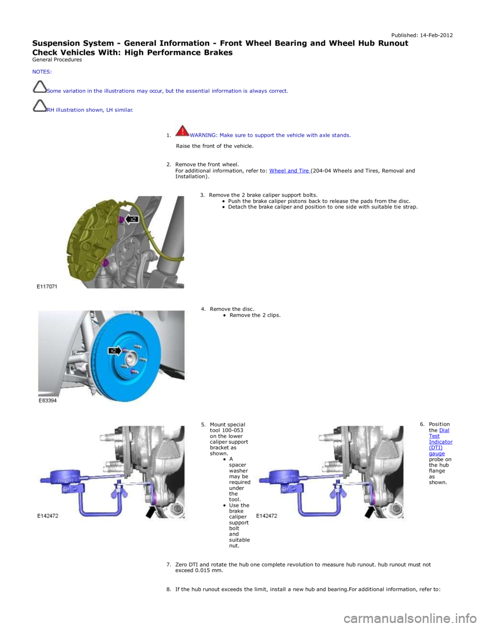
3. Remove the 2 brake caliper support bolts.
Push the brake caliper pistons back to release the pads from the disc. Detach the brake caliper and position to one side with suitable tie strap.
4. Remove the disc.
Remove the 2 clips.
5. Mount special tool 100-053 on the lower caliper support bracket as shown.
A
spacer washer may be required under the tool.
Use the brake caliper support bolt and suitable nut. 6. Position
the Dial Test Indicator (DTI) gauge probe on the hub flange as shown.
7. Zero DTI and rotate the hub one complete revolution to measure hub runout. hub runout must not exceed 0.015 mm.
8. If the hub runout exceeds the limit, install a new hub and bearing.For additional information, refer to:
Page 326 of 3039
Published:
27-Feb-2012
Suspension System - General Information - Rear Wheel Bearing and Wheel
Hub Ru
nout Check
General Procedures
NOTES:
RH illustra tion shown, LH sim ilar.
Some variat ion i n the illustra tions may o ccur, but the es senti al informa tion is always co rrect.
It is recommended that the DTI is capable of measurements of 0.005 mm.
1. WARNING: Make sure to support the vehicle with axle stands.
Raise the rear of the vehicle.
2. Remove the rear wheel.
For additional information, refer to: Wheel and Tire (204-04 Wheels and Tires, Removal and Installation).
3. Remove the 2 brake caliper support bolts.
Push the brake pads back to release the brake
caliper from the disc.
Detach the brake caliper and position to one side
with suitable tie strap.
4. Remove the disc.
Remove the 2 clips.
Page 336 of 3039

Front Suspension - Front Shock Absorber
Removal and Installation Published: 09-Oct-2012
NOTES: Removal
Fuse box release only required on removal of the RH front shock absorber.
Expansion tank release only required for supercharged variant removal of the LH front shock absorber.
All vehicles
1. WARNING: Do not work on or under a vehicle supported only by a
jack. Always support the vehicle on safety stands.
Raise and support the vehicle.
2. Remove the front wheel and tire.
For additional information, refer to: Wheel and Tire (204-04 Wheels and Tires, Removal and Installation).
3. Remove the front stabilizer bar link.
For additional information, refer to: Front Stabilizer Bar Link (204-01 Front Suspension, Removal and Installation).
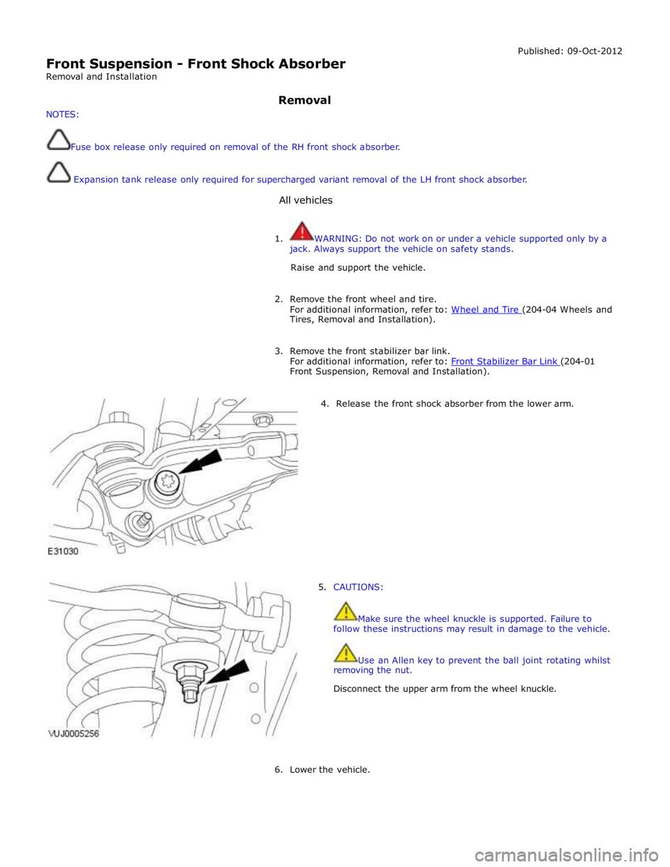
4. Release the front shock absorber from the lower arm.
5. CAUTIONS:
Make sure the wheel knuckle is supported. Failure to
follow these instructions may result in damage to the vehicle.
Use an Allen key to prevent the ball joint rotating whilst
removing the nut.
Disconnect the upper arm from the wheel knuckle.
6. Lower the vehicle.
Page 341 of 3039
8. CAUTIONS:
Use an Allen key to prevent the ball joint rotating whilst
installing the nut.
Make sure the wheel knuckle is supported. Failure to
follow these instructions may result in damage to the vehicle.
Secure the upper arm to the wheel knuckle.
Tighten the nut to 90 Nm.
9. Connect the front shock absorber and spring assembly to the
lower arm.
Tighten the bolt to 175 Nm.
10. Install the front stabilizer bar link.
For additional information, refer to: Front Stabilizer Bar Link (204-01 Front Suspension, Removal and Installation).
11. Install the front wheel and tire.
For additional information, refer to: Wheel and Tire (204-04 Wheels and Tires, Removal and Installation).
12. Lower the vehicle.
Page 342 of 3039

Front Suspension - Front Lower Arm
Removal and Installation
Removal Published: 11-May-2011
1. WARNING: Do not work on or under a vehicle supported only by a
jack. Always support the vehicle on safety stands.
Raise and support the vehicle.
2. Remove the air deflector.
For additional information, refer to: Air Deflector (501-02 Front End Body Panels, Removal and Installation).
3. Remove the front wheel and tire.
For additional information, refer to: Wheel and Tire (204-04 Wheels and Tires, Removal and Installation).
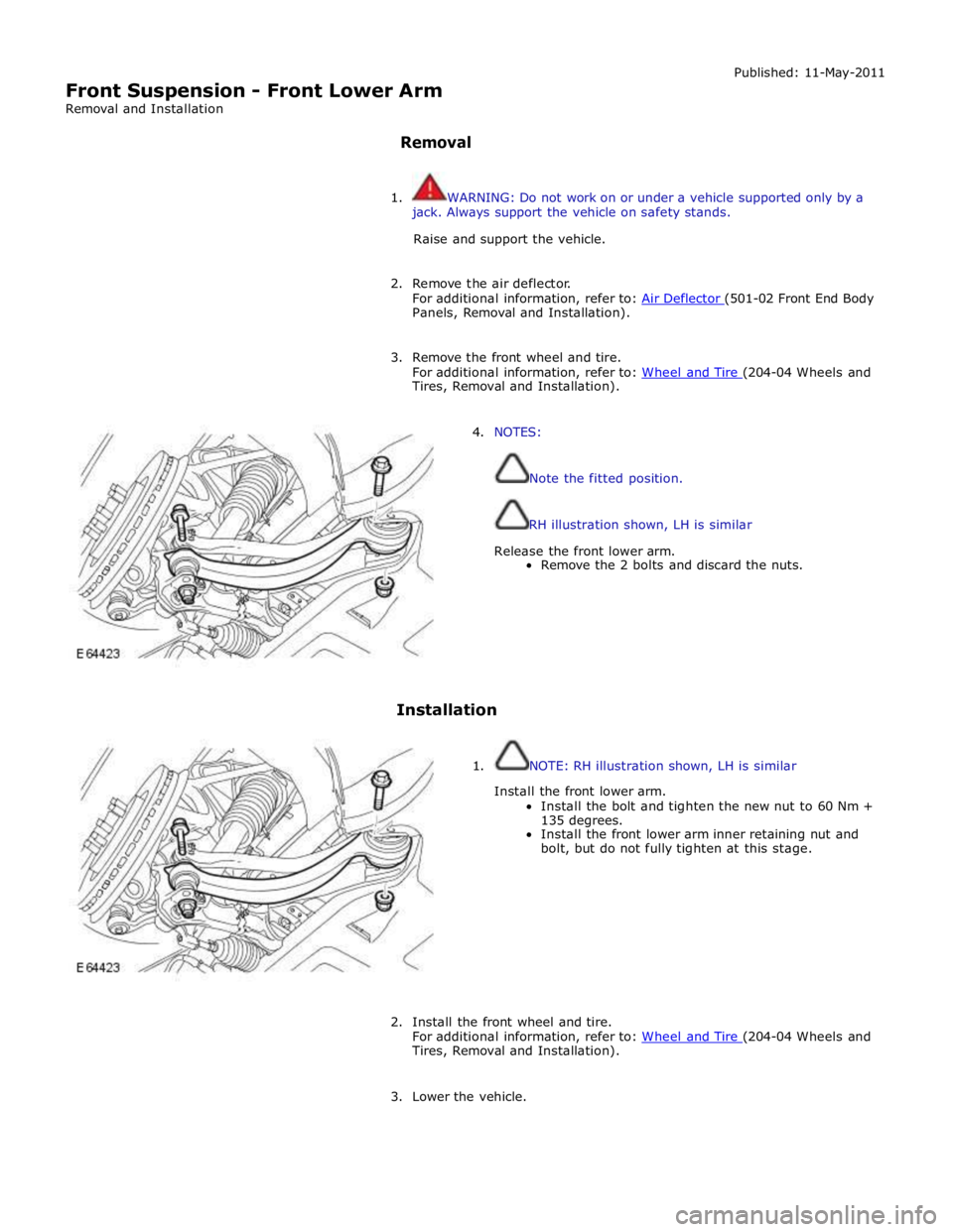
4. NOTES:
Note the fitted position.
RH illustration shown, LH is similar
Release the front lower arm.
Remove the 2 bolts and discard the nuts.
Installation
1. NOTE: RH illustration shown, LH is similar
Install the front lower arm.
Install the bolt and tighten the new nut to 60 Nm +
135 degrees.
Install the front lower arm inner retaining nut and
bolt, but do not fully tighten at this stage.
2. Install the front wheel and tire.
For additional information, refer to: Wheel and Tire (204-04 Wheels and Tires, Removal and Installation).
3. Lower the vehicle.
Page 344 of 3039
Panels, Removal and Installation).
3. WARNING: Do not work on or under a vehicle supported only by a jack.
Always support the vehicle on safety stands.
Raise and support the body.
4. Remove the wheel and tire.
For additional information, refer to: Wheel and Tire (204-04 Wheels and Tires, Removal and Installation).
5. Remove the stabilizer bar link.
For additional information, refer to: Front Stabilizer Bar Link (204-01 Front Suspension, Removal and Installation).
6. Release the tie rod. Ball joint splitter
204-327 Special Tool(s)