2010 JAGUAR XFR head light
[x] Cancel search: head lightPage 1828 of 3039
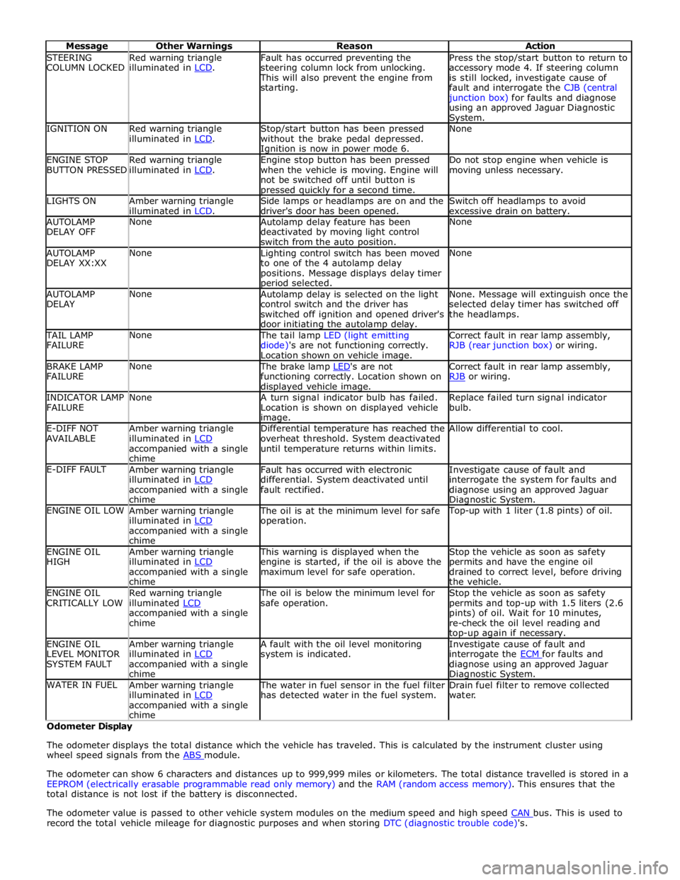
STEERING
COLUMN LOCKED Red warning triangle
illuminated in LCD. Fault has occurred preventing the
steering column lock from unlocking. This will also prevent the engine from
starting. Press the stop/start button to return to
accessory mode 4. If steering column
is still locked, investigate cause of
fault and interrogate the CJB (central junction box) for faults and diagnose
using an approved Jaguar Diagnostic System. IGNITION ON
Red warning triangle
illuminated in LCD. Stop/start button has been pressed
without the brake pedal depressed. Ignition is now in power mode 6. None ENGINE STOP
BUTTON PRESSED Red warning triangle
illuminated in LCD. Engine stop button has been pressed
when the vehicle is moving. Engine will
not be switched off until button is pressed quickly for a second time. Do not stop engine when vehicle is
moving unless necessary. LIGHTS ON
Amber warning triangle
illuminated in LCD. Side lamps or headlamps are on and the
driver's door has been opened. Switch off headlamps to avoid
excessive drain on battery. AUTOLAMP
DELAY OFF None
Autolamp delay feature has been
deactivated by moving light control
switch from the auto position. None AUTOLAMP
DELAY XX:XX None
Lighting control switch has been moved
to one of the 4 autolamp delay
positions. Message displays delay timer period selected. None AUTOLAMP
DELAY None
Autolamp delay is selected on the light
control switch and the driver has
switched off ignition and opened driver's
door initiating the autolamp delay. None. Message will extinguish once the
selected delay timer has switched off
the headlamps. TAIL LAMP
FAILURE None The tail lamp LED (light emitting
diode)'s are not functioning correctly.
Location shown on vehicle image. Correct fault in rear lamp assembly,
RJB (rear junction box) or wiring. BRAKE LAMP
FAILURE None The brake lamp LED's are not functioning correctly. Location shown on displayed vehicle image. Correct fault in rear lamp assembly,
RJB or wiring. INDICATOR LAMP
FAILURE None
A turn signal indicator bulb has failed.
Location is shown on displayed vehicle image. Replace failed turn signal indicator
bulb. E-DIFF NOT
AVAILABLE Amber warning triangle
illuminated in LCD accompanied with a single
chime Differential temperature has reached the
overheat threshold. System deactivated
until temperature returns within limits. Allow differential to cool. E-DIFF FAULT
Amber warning triangle
illuminated in LCD accompanied with a single
chime Fault has occurred with electronic
differential. System deactivated until
fault rectified. Investigate cause of fault and
interrogate the system for faults and
diagnose using an approved Jaguar Diagnostic System. ENGINE OIL LOW
Amber warning triangle
illuminated in LCD accompanied with a single
chime The oil is at the minimum level for safe
operation. Top-up with 1 liter (1.8 pints) of oil. ENGINE OIL
HIGH Amber warning triangle
illuminated in LCD accompanied with a single
chime This warning is displayed when the
engine is started, if the oil is above the
maximum level for safe operation. Stop the vehicle as soon as safety
permits and have the engine oil
drained to correct level, before driving
the vehicle. ENGINE OIL
CRITICALLY LOW Red warning triangle
illuminated LCD accompanied with a single
chime The oil is below the minimum level for
safe operation. Stop the vehicle as soon as safety
permits and top-up with 1.5 liters (2.6
pints) of oil. Wait for 10 minutes,
re-check the oil level reading and top-up again if necessary. ENGINE OIL
LEVEL MONITOR
SYSTEM FAULT Amber warning triangle
illuminated in LCD accompanied with a single
chime A fault with the oil level monitoring
system is indicated. Investigate cause of fault and
interrogate the ECM for faults and diagnose using an approved Jaguar Diagnostic System. WATER IN FUEL
Amber warning triangle
illuminated in LCD accompanied with a single
chime The water in fuel sensor in the fuel filter
has detected water in the fuel system. Drain fuel filter to remove collected
water. Odometer Display
The odometer displays the total distance which the vehicle has traveled. This is calculated by the instrument cluster using
wheel speed signals from the ABS module.
The odometer can show 6 characters and distances up to 999,999 miles or kilometers. The total distance travelled is stored in a
EEPROM (electrically erasable programmable read only memory) and the RAM (random access memory). This ensures that the
total distance is not lost if the battery is disconnected.
The odometer value is passed to other vehicle system modules on the medium speed and high speed CAN bus. This is used to record the total vehicle mileage for diagnostic purposes and when storing DTC (diagnostic trouble code)'s.
Page 1868 of 3039
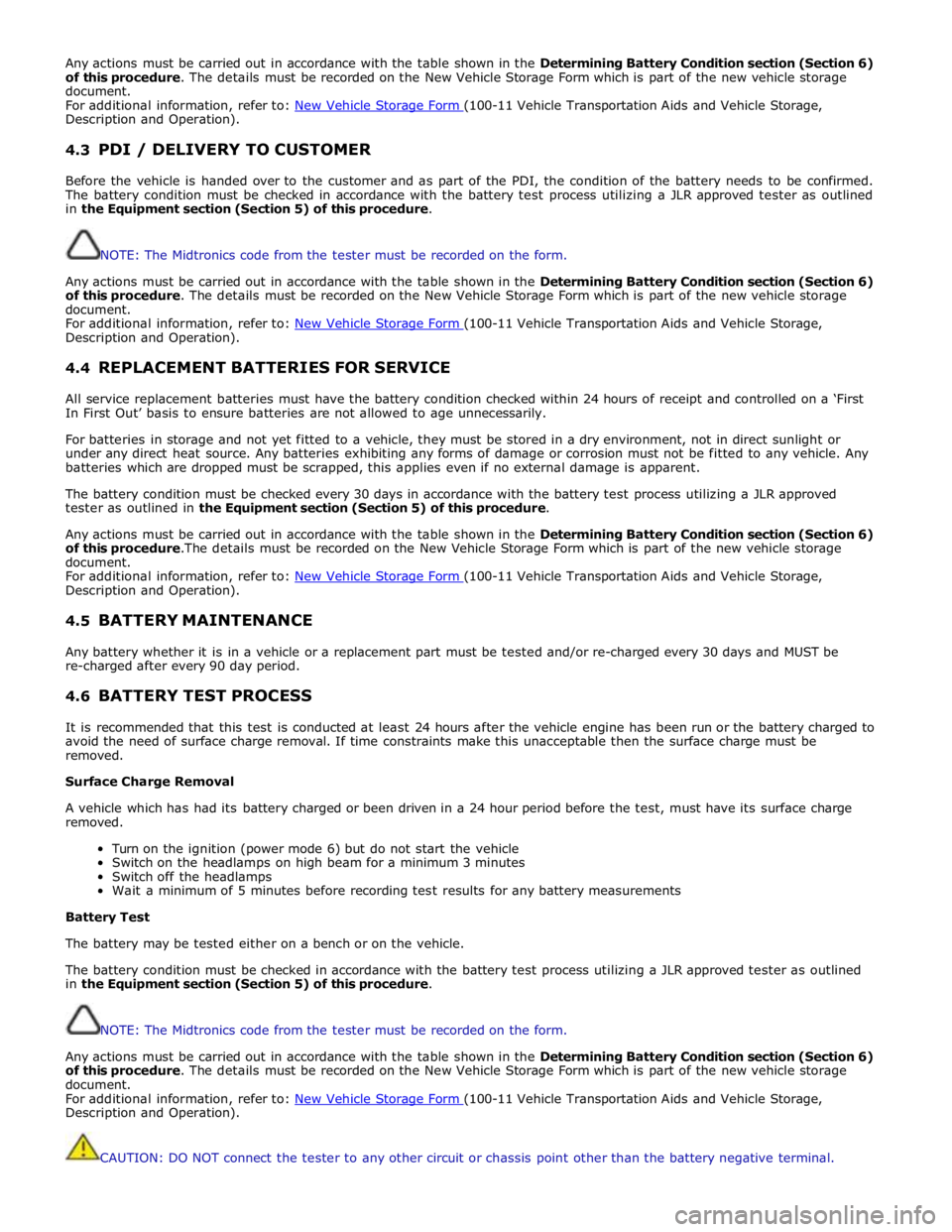
Any actions must be carried out in accordance with the table shown in the Determining Battery Condition section (Section 6)
of this procedure. The details must be recorded on the New Vehicle Storage Form which is part of the new vehicle storage
document.
For additional information, refer to: New Vehicle Storage Form (100-11 Vehicle Transportation Aids and Vehicle Storage, Description and Operation).
4.3 PDI / DELIVERY TO CUSTOMER
Before the vehicle is handed over to the customer and as part of the PDI, the condition of the battery needs to be confirmed.
The battery condition must be checked in accordance with the battery test process utilizing a JLR approved tester as outlined
in the Equipment section (Section 5) of this procedure.
NOTE: The Midtronics code from the tester must be recorded on the form.
Any actions must be carried out in accordance with the table shown in the Determining Battery Condition section (Section 6)
of this procedure. The details must be recorded on the New Vehicle Storage Form which is part of the new vehicle storage
document.
For additional information, refer to: New Vehicle Storage Form (100-11 Vehicle Transportation Aids and Vehicle Storage, Description and Operation).
4.4 REPLACEMENT BATTERIES FOR SERVICE
All service replacement batteries must have the battery condition checked within 24 hours of receipt and controlled on a ‘First
In First Out’ basis to ensure batteries are not allowed to age unnecessarily.
For batteries in storage and not yet fitted to a vehicle, they must be stored in a dry environment, not in direct sunlight or
under any direct heat source. Any batteries exhibiting any forms of damage or corrosion must not be fitted to any vehicle. Any
batteries which are dropped must be scrapped, this applies even if no external damage is apparent.
The battery condition must be checked every 30 days in accordance with the battery test process utilizing a JLR approved
tester as outlined in the Equipment section (Section 5) of this procedure.
Any actions must be carried out in accordance with the table shown in the Determining Battery Condition section (Section 6)
of this procedure.The details must be recorded on the New Vehicle Storage Form which is part of the new vehicle storage
document.
For additional information, refer to: New Vehicle Storage Form (100-11 Vehicle Transportation Aids and Vehicle Storage, Description and Operation).
4.5 BATTERY MAINTENANCE
Any battery whether it is in a vehicle or a replacement part must be tested and/or re-charged every 30 days and MUST be
re-charged after every 90 day period.
4.6 BATTERY TEST PROCESS
It is recommended that this test is conducted at least 24 hours after the vehicle engine has been run or the battery charged to
avoid the need of surface charge removal. If time constraints make this unacceptable then the surface charge must be
removed.
Surface Charge Removal
A vehicle which has had its battery charged or been driven in a 24 hour period before the test, must have its surface charge
removed.
Turn on the ignition (power mode 6) but do not start the vehicle
Switch on the headlamps on high beam for a minimum 3 minutes
Switch off the headlamps
Wait a minimum of 5 minutes before recording test results for any battery measurements
Battery Test
The battery may be tested either on a bench or on the vehicle.
The battery condition must be checked in accordance with the battery test process utilizing a JLR approved tester as outlined
in the Equipment section (Section 5) of this procedure.
NOTE: The Midtronics code from the tester must be recorded on the form.
Any actions must be carried out in accordance with the table shown in the Determining Battery Condition section (Section 6)
of this procedure. The details must be recorded on the New Vehicle Storage Form which is part of the new vehicle storage
document.
For additional information, refer to: New Vehicle Storage Form (100-11 Vehicle Transportation Aids and Vehicle Storage, Description and Operation).
CAUTION: DO NOT connect the tester to any other circuit or chassis point other than the battery negative terminal.
Page 1890 of 3039
1. Turn on the ignition but do not start the vehicle
2. Switch on the headlamps on high beam for a minimum 3 minutes
3. Switch off the headlamps
4. Wait a minimum of 5 minutes before recording test results for any battery measurements
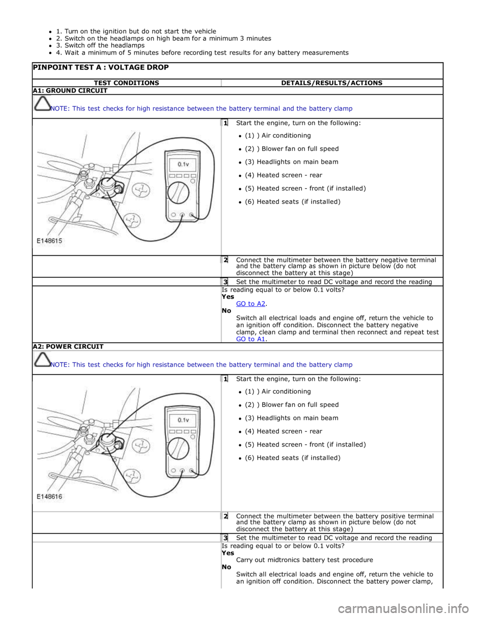
PINPOINT TEST A : VOLTAGE DROP TEST CONDITIONS DETAILS/RESULTS/ACTIONS A1: GROUND CIRCUIT
NOTE: This test checks for high resistance between the battery terminal and the battery clamp 1 Start the engine, turn on the following: (1) ) Air conditioning
(2) ) Blower fan on full speed
(3) Headlights on main beam
(4) Heated screen - rear
(5) Heated screen - front (if installed)
(6) Heated seats (if installed) 2 Connect the multimeter between the battery negative terminal and the battery clamp as shown in picture below (do not
disconnect the battery at this stage) 3 Set the multimeter to read DC voltage and record the reading Is reading equal to or below 0.1 volts? Yes
GO to A2. No
Switch all electrical loads and engine off, return the vehicle to
an ignition off condition. Disconnect the battery negative
clamp, clean clamp and terminal then reconnect and repeat test
GO to A1. A2: POWER CIRCUIT
NOTE: This test checks for high resistance between the battery terminal and the battery clamp 1 Start the engine, turn on the following: (1) ) Air conditioning
(2) ) Blower fan on full speed
(3) Headlights on main beam
(4) Heated screen - rear
(5) Heated screen - front (if installed)
(6) Heated seats (if installed) 2 Connect the multimeter between the battery positive terminal and the battery clamp as shown in picture below (do not
disconnect the battery at this stage) 3 Set the multimeter to read DC voltage and record the reading Is reading equal to or below 0.1 volts? Yes
Carry out midtronics battery test procedure
No
Switch all electrical loads and engine off, return the vehicle to
an ignition off condition. Disconnect the battery power clamp,
Page 1897 of 3039
NOTES:
BATTERY
CHARGE
If
the
state
of
charge
is
sufficient
this
step
will
not
show.
Go
to
next
step
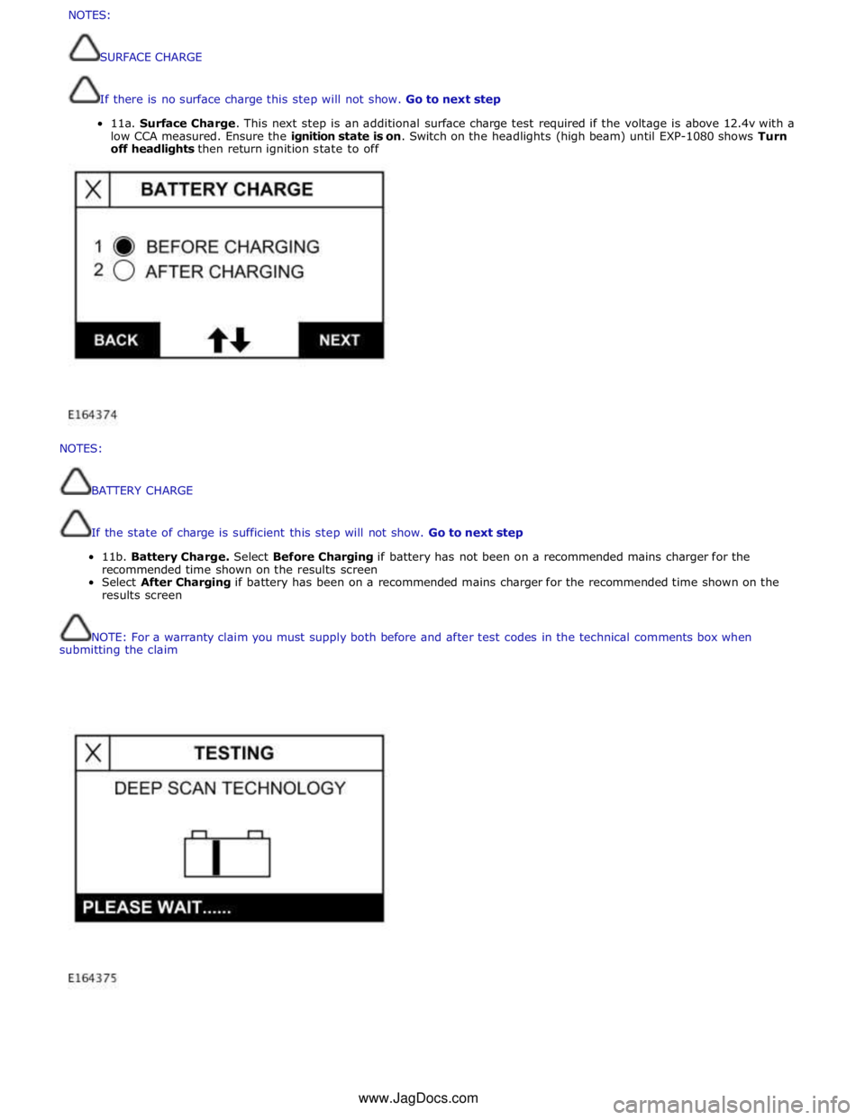
11b.
Battery
Charge.
Select
Before
Charging
if
battery
has
not
been
on
a
recommended
mains
charger
for
the
recommended
time
shown
on
the
results
screen
Select
After
Charging
if
battery
has
been
on
a
recommended
mains
charger
for
the
recommended
time
shown
on
the
results
screen
NOTE:
For
a
warranty
claim
you
must
supply
both
before
and
after
test
codes
in
the
technical
comments
box
when
submitting
the
claim
NOTES:
SURFACECHARGE
Ifthereisnosurfacechargethisstepwillnotshow.Gotonextstep
11a.SurfaceCharge.Thisnextstepisanadditionalsurfacechargetestrequiredifthevoltageisabove12.4vwith a
lowCCAmeasured.Ensuretheignitionstateis on.Switchontheheadlights(highbeam)untilEXP-1080showsTurn
offheadlightsthenreturnignitionstatetooffwww.JagDocs.com
Page 2020 of 3039
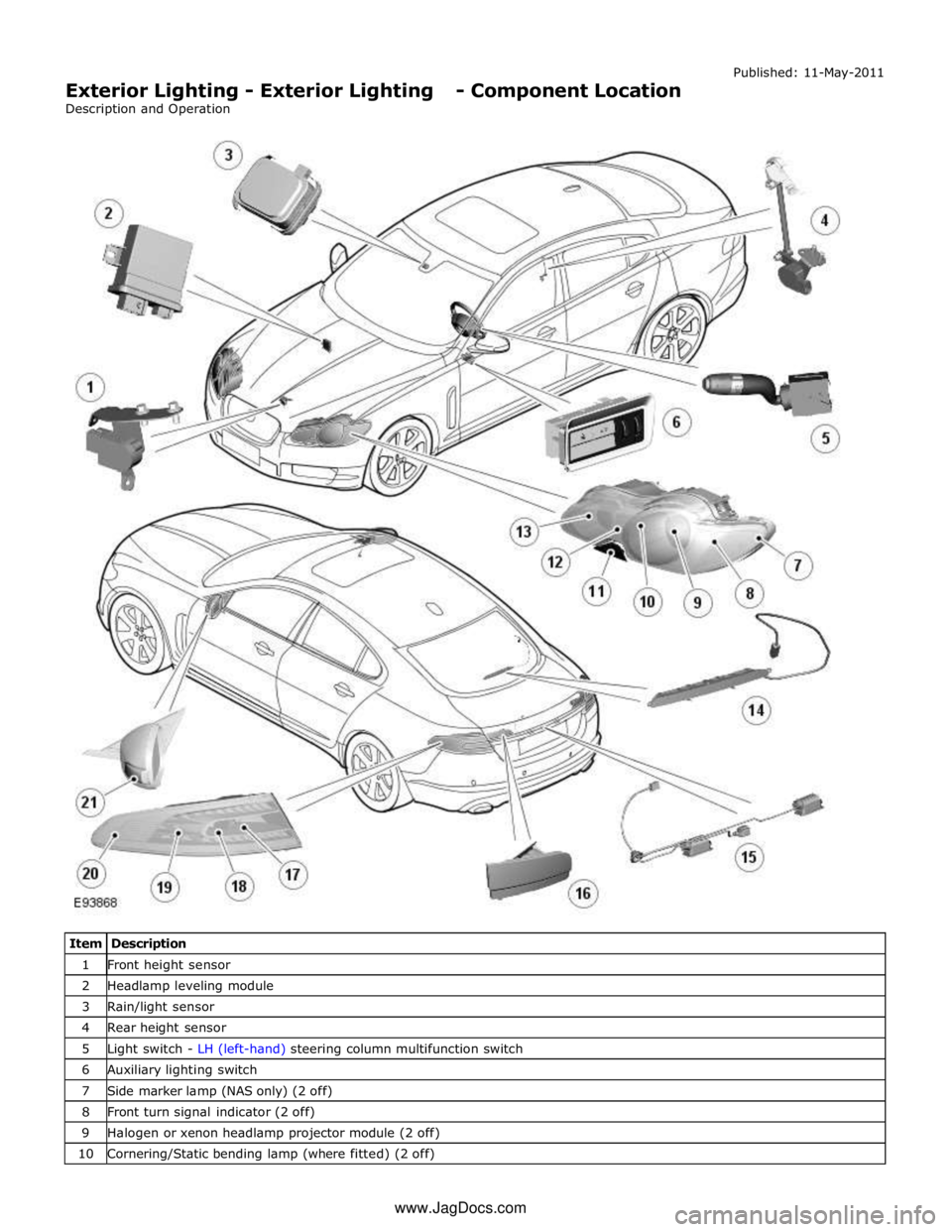
1 Front height sensor 2 Headlamp leveling module 3 Rain/light sensor 4 Rear height sensor 5 Light switch - LH (left-hand) steering column multifunction switch 6 Auxiliary lighting switch 7 Side marker lamp (NAS only) (2 off) 8 Front turn signal indicator (2 off) 9 Halogen or xenon headlamp projector module (2 off) 10 Cornering/Static bending lamp (where fitted) (2 off) www.JagDocs.com
Page 2022 of 3039
The lighting system has an 'auto' lights function which is controlled by the CJB on receipt of signals from the rain/light sensor located at the top of the windscreen. The exterior lights are turned on or off in response to ambient light signals from the
rain/light sensor on a LIN (local interconnect network) bus connection to the CJB . The auto lights can also be activated when the windshield wipers are activated by signals from the rain sensor, which is located at the top of the windshield or when the
driver activates the wipers in the fast wipe position.
Two levels of headlamp specification are available; halogen or xenon. In certain markets the headlamps feature a cornering
lamp or a static bending lamp which illuminates the area at the side of the vehicle when turning into driveways for example.
North American Specification (NAS) vehicles have a side marker lamp installed in the headlamp assembly. Replacement of any
of the headlamp bulbs requires removal of the headlamp assembly.
The tail lamp comprises two separate lamp assemblies. The turn signal indicator, side and stop lamps and reverse lamps are
located in each rear fender tail lamp assembly. The rear fog lamps are located in separate units attached to the luggage
compartment lid. A side marker lamp is fitted to the rear fender tail lamp assembly and is fitted in all markets.
Two systems of headlamp leveling are available; manual leveling which is only available on halogen headlamps and static
dynamic leveling which is available on xenon headlamps. The manual system uses a thumbwheel rheostat to adjust the
vertical alignment of the headlamps to compensate for differing vehicle loading. The static dynamic system uses height
sensors fitted to the front and rear suspension and a headlamp leveling module which periodically monitors the vehicle
attitude and adjusts the headlamp vertical alignment accordingly.
Page 2024 of 3039
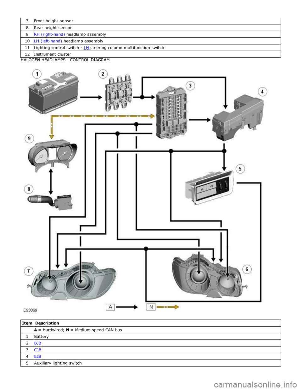
8 Rear height sensor 9 RH (right-hand) headlamp assembly 10 LH (left-hand) headlamp assembly 11 Lighting control switch - LH steering column multifunction switch 12 Instrument cluster HALOGEN HEADLAMPS - CONTROL DIAGRAM
Item Description A = Hardwired; N = Medium speed CAN bus 1 Battery 2 BJB 3 CJB 4 EJB 5 Auxiliary lighting switch
Page 2025 of 3039
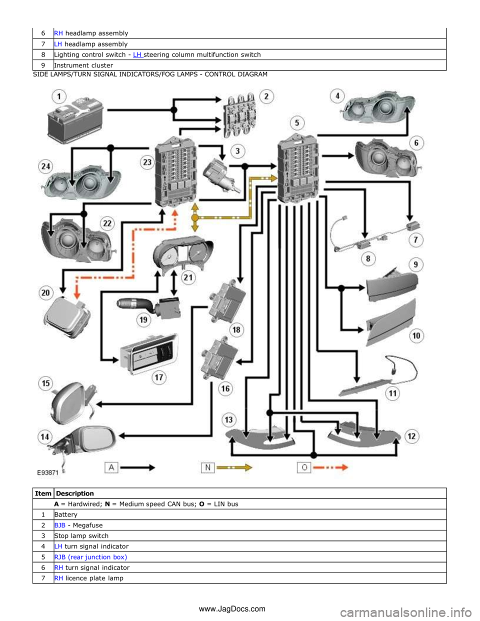
7 LH headlamp assembly 8 Lighting control switch - LH steering column multifunction switch 9 Instrument cluster SIDE LAMPS/TURN SIGNAL INDICATORS/FOG LAMPS - CONTROL DIAGRAM
Item Description A = Hardwired; N = Medium speed CAN bus; O = LIN bus 1 Battery 2 BJB - Megafuse 3 Stop lamp switch 4 LH turn signal indicator 5 RJB (rear junction box) 6 RH turn signal indicator 7 RH licence plate lamp www.JagDocs.com