Page 1522 of 3039
Published: 11-May-2011
Transmission/Transaxle Cooling - TDV6 3.0L Diesel /V8 5.0L Petrol/V8 S/C 5.0L Petrol - Transmission Fluid Cooler V8 5.0L Petrol/V8 S/C 5.0L Petrol
Removal and Installation
Removal
NOTE: Removal steps in this procedure may contain installation details.
1. WARNING: Make sure to support the vehicle with axle stands.
Raise and support the vehicle.
2. Refer to: Transmission Fluid Drain and Refill (307-01B Automatic Transmission/Transaxle - TDV6 3.0L Diesel /V8 5.0L Petrol/V8 S/C 5.0L
Petrol, General Procedures).
3. Refer to: Cooling System Draining and Vacuum Filling (303-03C Engine Cooling - V8 5.0L Petrol/V8 S/C 5.0L Petrol, General Procedures).
4. CAUTIONS:
Be prepared to collect escaping fluids.
Make sure that all openings are sealed. Use new
blanking caps.
5.
Page 1693 of 3039

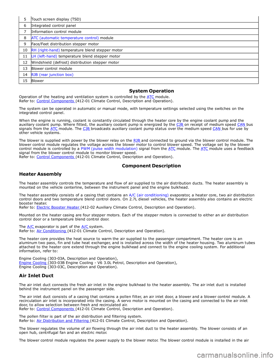
Touch screen display (TSD) 6 Integrated control panel 7 Information control module 8 ATC (automatic temperature control) module 9 Face/Feet distribution stepper motor 10 RH (right-hand) temperature blend stepper motor 11 LH (left-hand) temperature blend stepper motor 12 Windshield (defrost) distribution stepper motor 13 Blower control module 14 RJB (rear junction box) 15 Blower
System Operation
Operation of the heating and ventilation system is controlled by the ATC module. Refer to: Control Components (412-01 Climate Control, Description and Operation).
The system can be operated in automatic or manual mode, with temperature settings selected using the switches on the
integrated control panel.
When the engine is running, coolant is constantly circulated through the heater core by the engine coolant pump and the
auxiliary coolant pump. Where fitted, the auxiliary coolant pump is energized by the CJB on receipt of medium speed CAN bus signals from the ATC module. The CJB broadcasts auxiliary coolant pump status over the medium speed CAN bus for use by other vehicle systems.
The blower is supplied with power by the blower relay on the RJB and connected to ground via the blower control module. The blower control module regulates the voltage across the blower motor to control blower speed. The voltage set by the blower
control module is controlled by a PWM (pulse width modulation) signal from the ATC module. The ATC module uses a feedback signal from the blower control module to monitor blower speed.
Refer to: Control Components (412-01 Climate Control, Description and Operation).
Heater Assembly Component Description
The heater assembly controls the temperature and flow of air supplied to the air distribution ducts. The heater assembly is
mounted on the vehicle centerline, between the instrument panel and the engine bulkhead.
The heater assembly consists of a casing that contains an A/C (air conditioning) evaporator, a heater core, two air distribution
control doors and two temperature blend control doors. On 2.7L diesel vehicles, the heater assembly also contains an electric
booster heater.
Refer to: Electric Booster Heater (412-02 Auxiliary Climate Control, Description and Operation).
Mounted on the heater casing are four stepper motors. Each of the stepper motors is connected to either an air distribution
control door or a temperature blend control door.
The A/C evaporator is part of the A/C system. Refer to: Air Conditioning (412-01 Climate Control, Description and Operation).
The heater core provides the heat source to warm the air supplied to the passenger compartment. The heater core is an
aluminum two pass, fin and tube heat exchanger, and is installed across the width of the heater housing. Two aluminum tubes
attached to the heater core extend through the engine bulkhead and connect to the engine cooling system. For additional
information, refer to:
Engine Cooling (303-03A, Description and Operation),
Engine Cooling (303-03B Engine Cooling - V6 3.0L Petrol, Description and Operation), Engine Cooling (303-03C, Description and Operation).
Air Inlet Duct
The air inlet duct connects the fresh air inlet in the engine bulkhead to the heater assembly. The air inlet duct is installed
behind the instrument panel on the passenger side.
The air inlet duct consists of a casing that contains a pollen filter, an air inlet door, a blower and a blower control module. A
recirculation air inlet is incorporated into the casing. A servo motor is mounted on the casing and connected to the air inlet
door, to allow selection between fresh and recirculated air.
Refer to: Control Components (412-01 Climate Control, Description and Operation). The pollen filter is part of the air distribution and filtering system.
Refer to: Air Distribution and Filtering (412-01 Climate Control, Description and Operation).
The blower regulates the volume of air flowing through the air inlet duct to the heater assembly. The blower consists of an
open hub, centrifugal fan and an electric motor.
The blower control module regulates the power supply to the blower motor. The blower control module is installed in the air
Page 2469 of 3039

Instrument Panel and Console - Instrument Panel Console
Removal and Installation Published: 11-May-2011
Removal
CAUTIONS:
Inspect the seals, replace if damaged.
Inspect the O-rings, replace if damaged.
NOTE: Removal steps in this procedure may contain installation details.
All vehicles
1. Refer to: Battery Disconnect and Connect (414-01 Battery, Mounting and Cables, General Procedures).
2. WARNING: Make sure to support the vehicle with axle stands.
Raise and support the vehicle.
Vehicles with supercharger
3. Refer to: Cooling System Draining, Filling and Bleeding - V8 S/C 5.0L Petrol (303-03C Engine Cooling - V8 5.0L Petrol/V8 S/C 5.0L Petrol, General Procedures).
Vehicles without supercharger
4. Refer to: Cooling System Draining, Filling and Bleeding - V8 5.0L Petrol (303-03C Engine Cooling - V8 5.0L Petrol/V8 S/C 5.0L Petrol, General
Procedures).
Vehicles with diesel engine
5. Refer to: Cooling System Draining, Filling and Bleeding (303-03A Engine Cooling - TDV6 3.0L Diesel, General Procedures).
All vehicles
6. Refer to: Air Conditioning (A/C) System Recovery, Evacuation and Charging (412-00 Climate Control System - General Information, General Procedures).
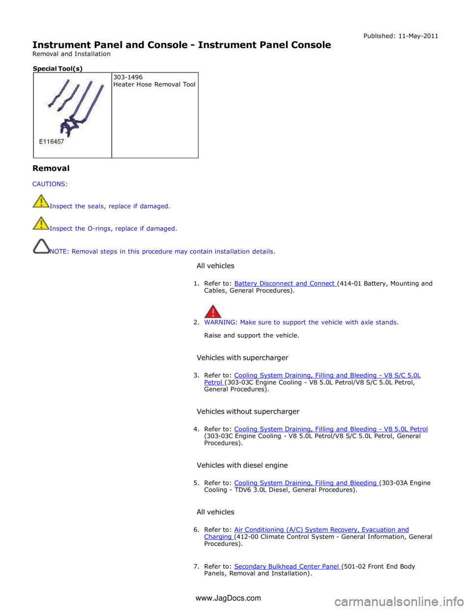
7. Refer to: Secondary Bulkhead Center Panel (501-02 Front End Body Panels, Removal and Installation). 303-1496
Heater Hose Removal Tool Special Tool(s)
www.JagDocs.com
Page 2821 of 3039

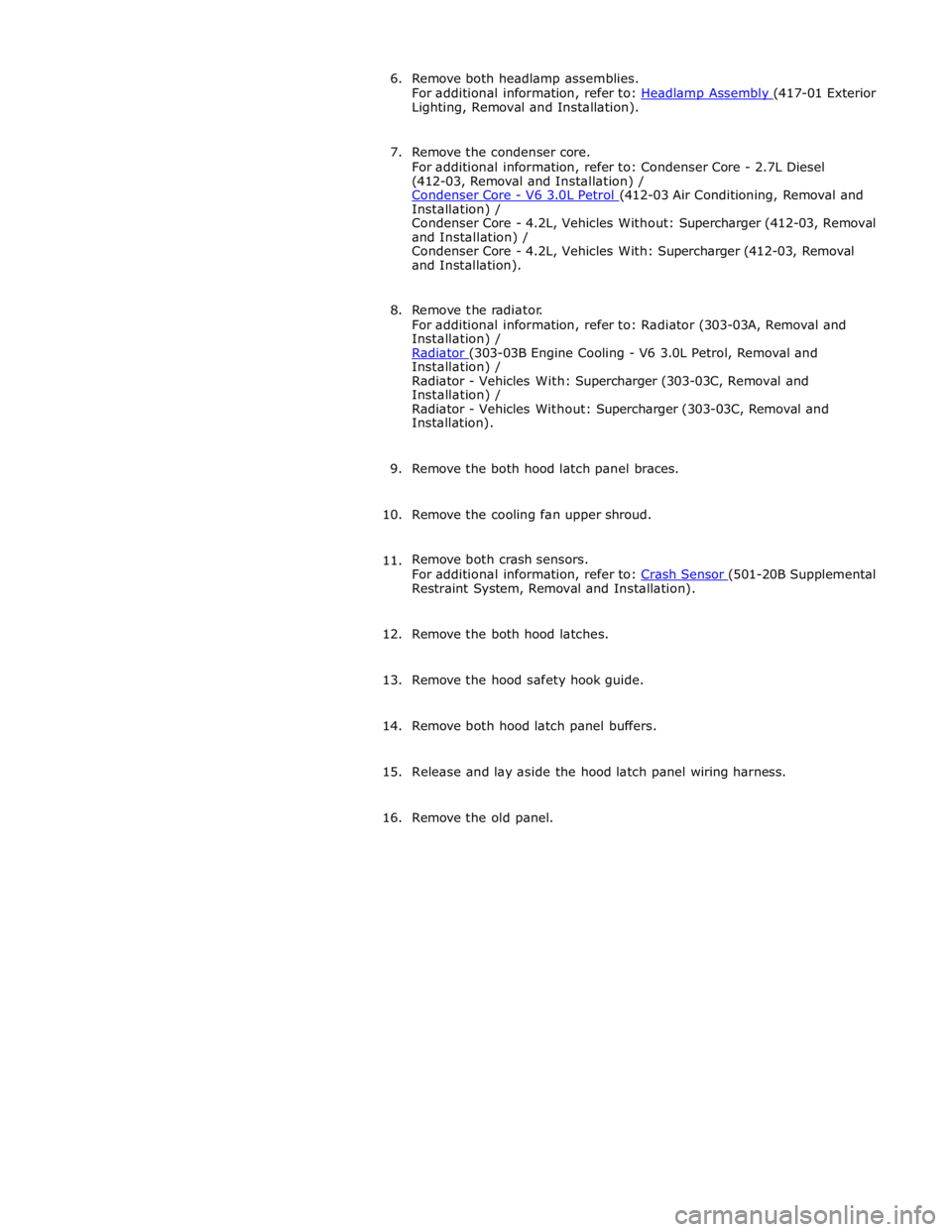
Lighting, Removal and Installation).
7. Remove the condenser core.
For additional information, refer to: Condenser Core - 2.7L Diesel
(412-03, Removal and Installation) /
Condenser Core - V6 3.0L Petrol (412-03 Air Conditioning, Removal and Installation) /
Condenser Core - 4.2L, Vehicles Without: Supercharger (412-03, Removal
and Installation) /
Condenser Core - 4.2L, Vehicles With: Supercharger (412-03, Removal
and Installation).
8. Remove the radiator.
For additional information, refer to: Radiator (303-03A, Removal and
Installation) /
Radiator (303-03B Engine Cooling - V6 3.0L Petrol, Removal and Installation) /
Radiator - Vehicles With: Supercharger (303-03C, Removal and
Installation) /
Radiator - Vehicles Without: Supercharger (303-03C, Removal and
Installation).
9. Remove the both hood latch panel braces.
10. Remove the cooling fan upper shroud.
11. Remove both crash sensors.
For additional information, refer to: Crash Sensor (501-20B Supplemental Restraint System, Removal and Installation).
12. Remove the both hood latches.
13. Remove the hood safety hook guide.
14. Remove both hood latch panel buffers.
15. Release and lay aside the hood latch panel wiring harness.
16. Remove the old panel.
Page:
< prev 1-8 9-16 17-24