2010 JAGUAR XFR ESP
[x] Cancel search: ESPPage 2626 of 3039
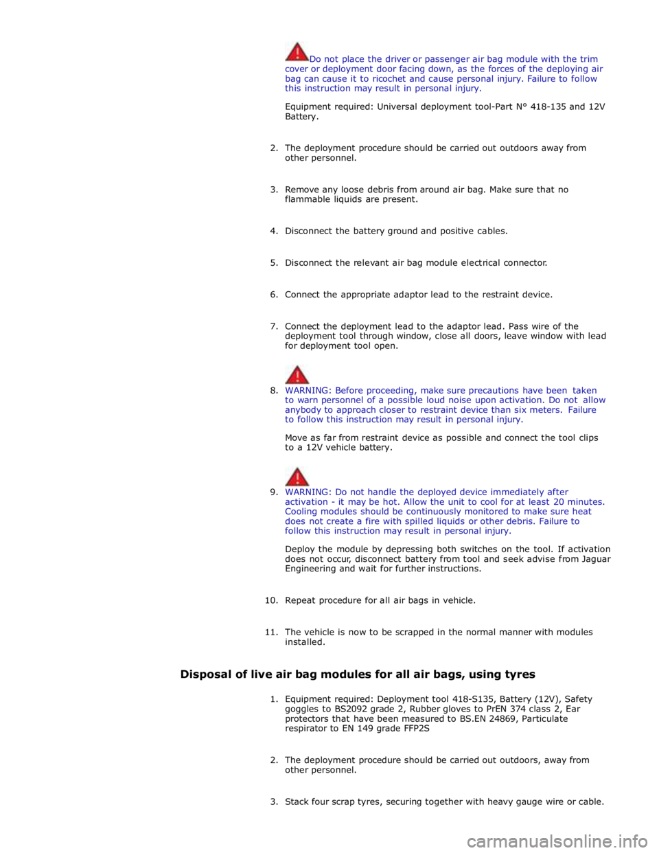
Do not place the driver or passenger air bag module with the trim
cover or deployment door facing down, as the forces of the deploying air
bag can cause it to ricochet and cause personal injury. Failure to follow
this instruction may result in personal injury.
Equipment required: Universal deployment tool-Part N° 418-135 and 12V
Battery.
2. The deployment procedure should be carried out outdoors away from
other personnel.
3. Remove any loose debris from around air bag. Make sure that no
flammable liquids are present.
4. Disconnect the battery ground and positive cables.
5. Disconnect the relevant air bag module electrical connector.
6. Connect the appropriate adaptor lead to the restraint device.
7. Connect the deployment lead to the adaptor lead. Pass wire of the
deployment tool through window, close all doors, leave window with lead
for deployment tool open.
8. WARNING: Before proceeding, make sure precautions have been taken
to warn personnel of a possible loud noise upon activation. Do not allow
anybody to approach closer to restraint device than six meters. Failure
to follow this instruction may result in personal injury.
Move as far from restraint device as possible and connect the tool clips
to a 12V vehicle battery.
9. WARNING: Do not handle the deployed device immediately after
activation - it may be hot. Allow the unit to cool for at least 20 minutes.
Cooling modules should be continuously monitored to make sure heat
does not create a fire with spilled liquids or other debris. Failure to
follow this instruction may result in personal injury.
Deploy the module by depressing both switches on the tool. If activation
does not occur, disconnect battery from tool and seek advise from Jaguar
Engineering and wait for further instructions.
10. Repeat procedure for all air bags in vehicle.
11. The vehicle is now to be scrapped in the normal manner with modules
installed.
Disposal of live air bag modules for all air bags, using tyres
1. Equipment required: Deployment tool 418-S135, Battery (12V), Safety
goggles to BS2092 grade 2, Rubber gloves to PrEN 374 class 2, Ear
protectors that have been measured to BS.EN 24869, Particulate
respirator to EN 149 grade FFP2S
2. The deployment procedure should be carried out outdoors, away from
other personnel.
3. Stack four scrap tyres, securing together with heavy gauge wire or cable.
Page 2684 of 3039
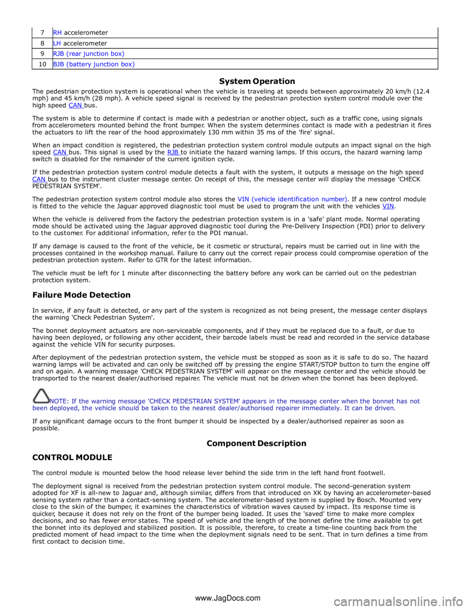
7 RH accelerometer 8 LH accelerometer 9 RJB (rear junction box) 10 BJB (battery junction box)
System Operation
The pedestrian protection system is operational when the vehicle is traveling at speeds between approximately 20 km/h (12.4
mph) and 45 km/h (28 mph). A vehicle speed signal is received by the pedestrian protection system control module over the
high speed CAN bus.
The system is able to determine if contact is made with a pedestrian or another object, such as a traffic cone, using signals
from accelerometers mounted behind the front bumper. When the system determines contact is made with a pedestrian it fires
the actuators to lift the rear of the hood approximately 130 mm within 35 ms of the 'fire' signal.
When an impact condition is registered, the pedestrian protection system control module outputs an impact signal on the high
speed CAN bus. This signal is used by the RJB to initiate the hazard warning lamps. If this occurs, the hazard warning lamp switch is disabled for the remainder of the current ignition cycle.
If the pedestrian protection system control module detects a fault with the system, it outputs a message on the high speed
CAN bus to the instrument cluster message center. On receipt of this, the message center will display the message 'CHECK PEDESTRIAN SYSTEM'.
The pedestrian protection system control module also stores the VIN (vehicle identification number). If a new control module
is fitted to the vehicle the Jaguar approved diagnostic tool must be used to program the unit with the vehicles VIN.
When the vehicle is delivered from the factory the pedestrian protection system is in a 'safe' plant mode. Normal operating
mode should be activated using the Jaguar approved diagnostic tool during the Pre-Delivery Inspection (PDI) prior to delivery
to the customer. For additional information, refer to the PDI manual.
If any damage is caused to the front of the vehicle, be it cosmetic or structural, repairs must be carried out in line with the
processes contained in the workshop manual. Failure to carry out the correct repair process could compromise operation of the
pedestrian protection system. Refer to GTR for the latest information.
The vehicle must be left for 1 minute after disconnecting the battery before any work can be carried out on the pedestrian
protection system.
Failure Mode Detection
In service, if any fault is detected, or any part of the system is recognized as not being present, the message center displays
the warning 'Check Pedestrian System'.
The bonnet deployment actuators are non-serviceable components, and if they must be replaced due to a fault, or due to
having been deployed, or following any other accident, their barcode labels must be read and recorded in the service database
against the vehicle VIN for security purposes.
After deployment of the pedestrian protection system, the vehicle must be stopped as soon as it is safe to do so. The hazard
warning lamps will be activated and can only be switched off by pressing the engine START/STOP button to turn the engine off
and on again. A warning message 'CHECK PEDESTRIAN SYSTEM' will appear on the message center and the vehicle should be
transported to the nearest dealer/authorised repairer. The vehicle must not be driven when the bonnet has been deployed.
NOTE: If the warning message 'CHECK PEDESTRIAN SYSTEM' appears in the message center when the bonnet has not
been deployed, the vehicle should be taken to the nearest dealer/authorised repairer immediately. It can be driven.
If any significant damage occurs to the front bumper it should be inspected by a dealer/authorised repairer as soon as
possible.
CONTROL MODULE Component Description
The control module is mounted below the hood release lever behind the side trim in the left hand front footwell.
The deployment signal is received from the pedestrian protection system control module. The second-generation system
adopted for XF is all-new to Jaguar and, although similar, differs from that introduced on XK by having an accelerometer-based
sensing system rather than a contact-sensing system. The accelerometer-based system is supplied by Bosch. Mounted very
close to the skin of the bumper, it examines the characteristics of vibration waves caused by impact. Its response time is
quicker, because it does not rely on the front of the bumper being loaded. It uses the 'saved' time to make more complex
decisions, and so has fewer error states. The speed of vehicle and the length of the bonnet define the time available to get
the bonnet into its deployed and stabilized position. It is possible, therefore, to create a time-line counting back from the
predicted moment of head impact to the time when the deployment signals need to be sent. That in turn defines a time from
first contact to decision time.
www.JagDocs.com
Page 2688 of 3039
Diagnostic Trouble Codes (DTCs) and refer to the DTC Index
5. Check DDW for open campaigns. Refer to the corresponding bulletins and SSMs which may be valid for the specific
customer complaint and carry out the recommendations as required
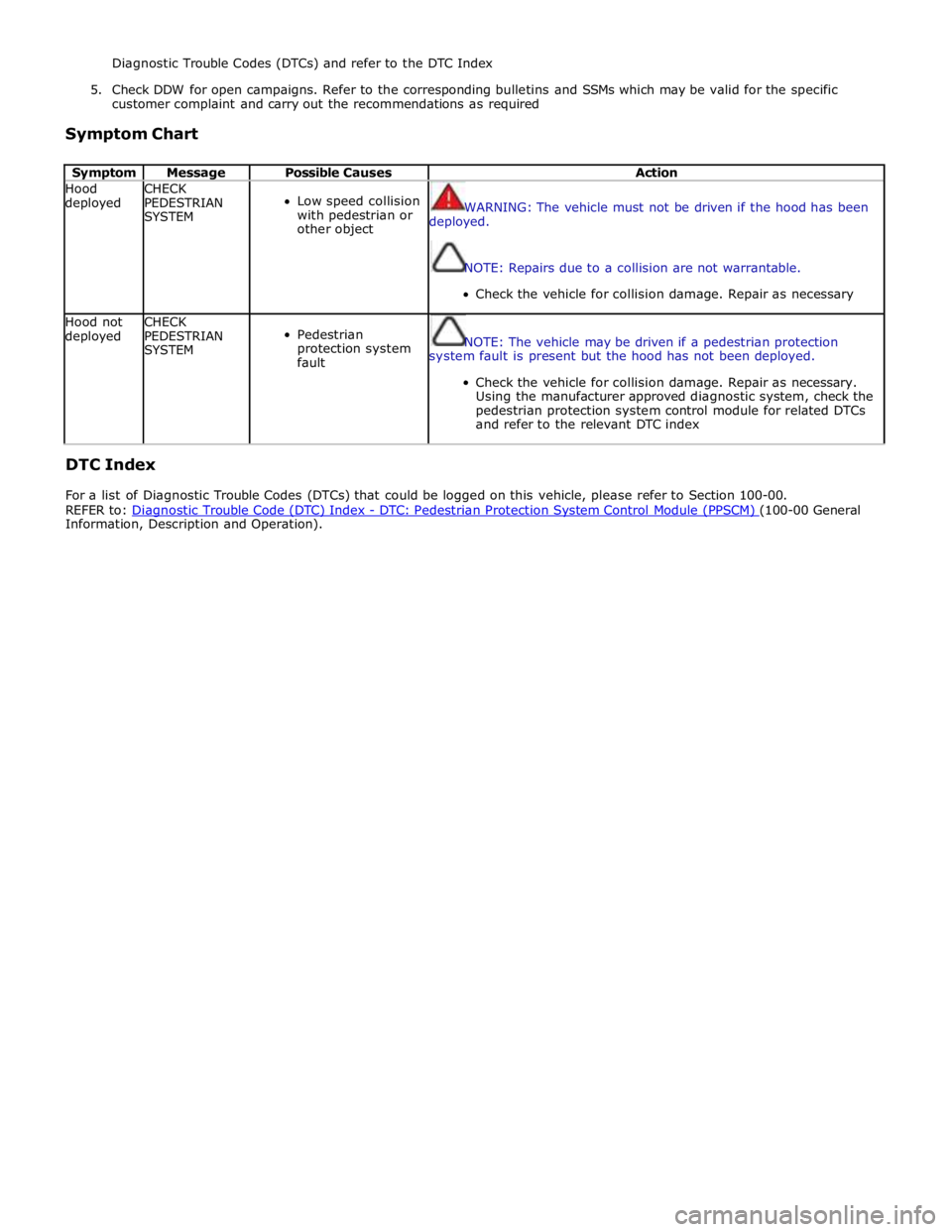
Symptom Chart
Symptom Message Possible Causes Action Hood
deployed CHECK
PEDESTRIAN
SYSTEM
Low speed collision
with pedestrian or
other object
WARNING: The vehicle must not be driven if the hood has been
deployed.
NOTE: Repairs due to a collision are not warrantable.
Check the vehicle for collision damage. Repair as necessary Hood not
deployed CHECK
PEDESTRIAN
SYSTEM
Pedestrian
protection system
fault
NOTE: The vehicle may be driven if a pedestrian protection
system fault is present but the hood has not been deployed.
Check the vehicle for collision damage. Repair as necessary.
Using the manufacturer approved diagnostic system, check the
pedestrian protection system control module for related DTCs
and refer to the relevant DTC index
DTC Index
For a list of Diagnostic Trouble Codes (DTCs) that could be logged on this vehicle, please refer to Section 100-00.
REFER to: Diagnostic Trouble Code (DTC) Index - DTC: Pedestrian Protection System Control Module (PPSCM) (100-00 General Information, Description and Operation).
Page 2694 of 3039

Part N-umber
Body Repairs - General Information - Body Repairs
Description and Operation
General Information
Introduction Published: 11-May-2011
The body plays a significant role in the increasing trend of ever more rapidly changing model variants. The different customer
groups are strongly influenced by the design and shape of the body. At the same time the stability of the body plays the most
important part in ensuring passenger and driver safety. Lightweight construction, alternative materials, composite materials,
plastics and appropriate joining processes are all design features that characterise modern Jaguar vehicle bodies.
In terms of manufacturing technology, modern safety cell bodies can be produced almost without any problems. Jaguar
guarantee high quality standards by ensuring that mechanical strength properties are tried and tested in numerous computer
simulations, crash tests, by testing materials and by employing sophisticated manufacturing technologies. In the event of
repairs it is vital that the production quality standards are upheld. This requires a well-equipped workshop, and places
particular emphasis on the qualifications of the workshop technicians. Up-to-date knowledge of current manufacturing
technologies and continuous training on new repair methods and techniques are vital for high-quality body repairs. The model-
specific repair manuals and the general repair techniques provide valuable support when undertaking body repairs.
Always follow the repair instructions published in this manual. Failure to observe this instruction can result in serious
impairment of vehicle safety. All specified safety requirements must be met after the work has been carried out.
Vehicle design
The body
The XF adopts the latest generation steels, especially in the upper body – including high carbon steels, dual-phase,
hot-formed boron steels, and bake-hardened steels to form a vertical safety ‘ring’ around the occupant cell. As well as
combining strength with lightness, these steels improve corrosion resistance, by making best use of zinc and improving e-coat
paint flow – and new thinking means that in spite of their strength, the XF’s A and B-pillars are impressively slim, to the
benefit of both visibility and accessibility. Similarly, the lower sills are the first component on any Jaguar to use incredibly
strong, dual-phase DP600 steel.
The safety of the driver and the passengers is paramount for every body design. There are two key safety aspects in the body:
Safety passenger cell
Crumple zones
Safety passenger cell
Stable pillars, rocker panel and door profiles.
Side impact protection in the doors.
Doors are designed to open even in the event of extreme deformation.
Crumple zone
Dynamic absorption of deforming forces.
Protection of the passenger cell. www.JagDocs.com
Page 2715 of 3039
MIG/MAG welding
Setting up the equipment and co-ordinating the welding parameters.
Any joins that are MIG/MAG welded in production must also be MIG/MAG welded during repairs. Also during repairs,
some resistance spot welds need to be replaced by plug welds.
If access is difficult, or if a suitably powerful spot welder (see above) for total panel thicknesses of 3 mm or more is
not available, resistance spot welding must be partially replaced by plug welding during repairs. In this case, the
increased time needed and the correspondingly more demanding corrosion protection requirements, must be taken into
account.
Welding repairs can only be carried out properly if the equipment is set up correctly and all the welding parameters are
co-ordinated.
Equipment:
- Set up the equipment as directed by the manufacturer.
- The hoses must be untwisted.
- The core must be free of abraded rod particles.
- The gas and current nozzles must be free of slag and scale residue.
- Pay attention to the quality of the welding rod and the throughput of gas.
Body:
- Make sure that the joint surface is perfect.
- Prepare a bare metal joint surface.
- Maintain the correct gaps (formation of roots).
Notes on technique/method:
NOTES:
The increased application of heat during MIG welding destroys the welding primer/zinc layer over a much larger
area than during resistance spot welding, as a result of which much more care needs to be taken when applying
anti-corrosion protection afterwards.
A test weld should always be carried out to make sure that the welded joint is not just a surface connection.
- Attach the ground cable right next to the welding point (Make sure that good contact is made).
- During plug welding start welding on the lower panel to Make sure adequate penetration.
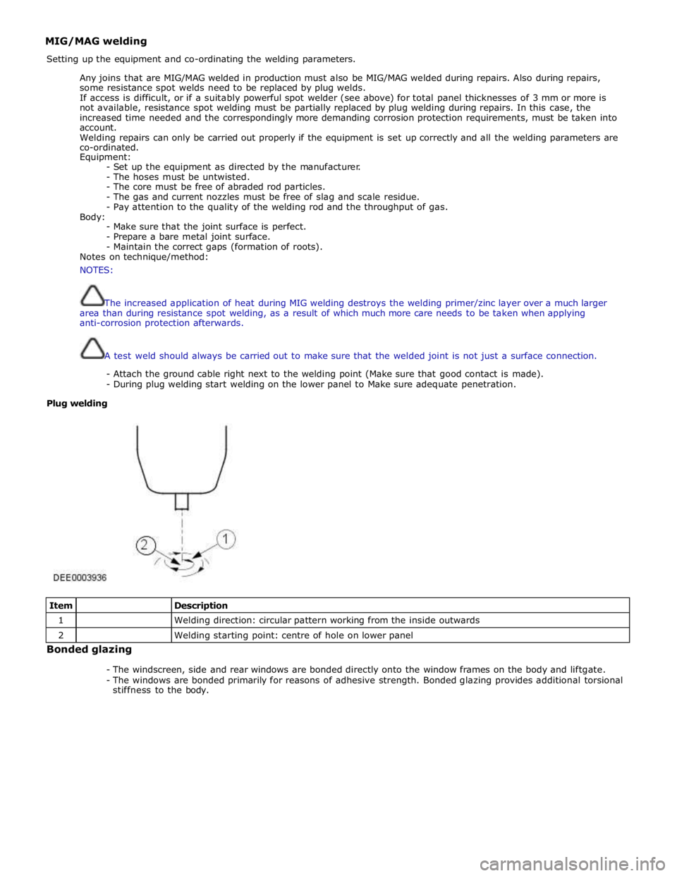
Plug welding
Item
Description 1
Welding direction: circular pattern working from the inside outwards 2
Welding starting point: centre of hole on lower panel Bonded glazing
- The windscreen, side and rear windows are bonded directly onto the window frames on the body and liftgate.
- The windows are bonded primarily for reasons of adhesive strength. Bonded glazing provides additional torsional
stiffness to the body.
Page 2731 of 3039
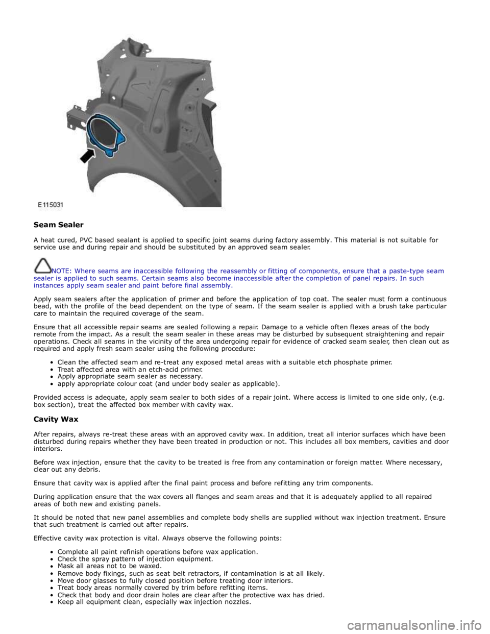
Seam Sealer
A heat cured, PVC based sealant is applied to specific joint seams during factory assembly. This material is not suitable for
service use and during repair and should be substituted by an approved seam sealer.
NOTE: Where seams are inaccessible following the reassembly or fitting of components, ensure that a paste-type seam
sealer is applied to such seams. Certain seams also become inaccessible after the completion of panel repairs. In such
instances apply seam sealer and paint before final assembly.
Apply seam sealers after the application of primer and before the application of top coat. The sealer must form a continuous
bead, with the profile of the bead dependent on the type of seam. If the seam sealer is applied with a brush take particular
care to maintain the required coverage of the seam.
Ensure that all accessible repair seams are sealed following a repair. Damage to a vehicle often flexes areas of the body
remote from the impact. As a result the seam sealer in these areas may be disturbed by subsequent straightening and repair
operations. Check all seams in the vicinity of the area undergoing repair for evidence of cracked seam sealer, then clean out as
required and apply fresh seam sealer using the following procedure:
Clean the affected seam and re-treat any exposed metal areas with a suitable etch phosphate primer.
Treat affected area with an etch-acid primer.
Apply appropriate seam sealer as necessary.
apply appropriate colour coat (and under body sealer as applicable).
Provided access is adequate, apply seam sealer to both sides of a repair joint. Where access is limited to one side only, (e.g.
box section), treat the affected box member with cavity wax.
Cavity Wax
After repairs, always re-treat these areas with an approved cavity wax. In addition, treat all interior surfaces which have been
disturbed during repairs whether they have been treated in production or not. This includes all box members, cavities and door
interiors.
Before wax injection, ensure that the cavity to be treated is free from any contamination or foreign matter. Where necessary,
clear out any debris.
Ensure that cavity wax is applied after the final paint process and before refitting any trim components.
During application ensure that the wax covers all flanges and seam areas and that it is adequately applied to all repaired
areas of both new and existing panels.
It should be noted that new panel assemblies and complete body shells are supplied without wax injection treatment. Ensure
that such treatment is carried out after repairs.
Effective cavity wax protection is vital. Always observe the following points:
Complete all paint refinish operations before wax application.
Check the spray pattern of injection equipment.
Mask all areas not to be waxed.
Remove body fixings, such as seat belt retractors, if contamination is at all likely.
Move door glasses to fully closed position before treating door interiors.
Treat body areas normally covered by trim before refitting items.
Check that body and door drain holes are clear after the protective wax has dried.
Keep all equipment clean, especially wax injection nozzles.
Page 2735 of 3039
Side windows
In the case of side windows, the same problems can arise as for a windscreen. The same corrective actions must therefore be
used.
Door seal
Diagnosis:
- Water ingress in the lower part of the interior door trim or in the rocker panel area.
Cause:
- The water shield fitted behind the interior door trim exists to drain off water that has entered the door via the
drainage holes, either downwards or outwards. If the water shield seal is damaged or has been fitted incorrectly,
then water can get into the passenger compartment.
- In addition to this, the drainage holes can become clogged with leaves, dirt or excess cavity protection agents.
Water gathers in the door and ingresses into the passenger compartment.
- Check water shield for damage or correct fitting.
- If the water shield needs to be re-bonded, then approved seam sealer should be used.
- Before the water shield is installed, the drainage holes must be checked for unhindered flow.
Door seals
Diagnosis:
- Ingress of water into the rocker panel area
Cause:
- Insufficient clamping load between seal and door.
Corrective action:
NOTE: When adjusting the clamping load, the profile alignment of the relevant components must always be taken
into consideration.
NOTE: Do not realign the flange too far in the direction of the door, as this can reduce the bearing surface of the
seal to the door.
- Check clamping load:
- The easiest way to check the clamping load of a seal to the respective bearing surface is by means of a paper
strip test. This consists of trapping strips of paper at various points between the door and the seal, and fully
closing the door. If it is possible to pull out the paper with no great resistance, then the clamping load is too
low.
- Adjust the clamping load:
- The clamping load is normally adjusted using the striker. When doing so, the edge alignment from the door to
the side panel, or from the front door to the rear door must be taken into account.
- Another setting method is to realign the panel flange for the seal mounting. The clamping load is increased by
moving the flange towards the door.
- Check the bearing surface:
- Apply chalk evenly to the surface of the seal. Evenly coat the bearing surface of the door with Vaseline.
- Close the door fully, the lock must engage. Open the door. The imprint of the chalk (bearing surface) can be
identified in the film of Vaseline.
- The bearing surface should be at least 5mm across at all points.
Other causes:
- The door seal must completely seal the door where it meets the bodywork.
- Water can ingress directly or indirectly into the interior of the vehicle if the seal is damaged at any point.
Corrective action:
- A damaged or worn door seal must always be renewed in full.
- When renewing the seal, the following must be taken into account:
- Always fit the seal first in the area of the narrow radii (corner points).
- Next, secure the seal to the flange evenly by tapping lightly with a rubber hammer. The installed seal must not
be kinked at any point.
NOTE: The prescribed length of a seal must not be shortened.
Other cause:
- The door seal is attached to the welded flange all the way round. If this welded flange is uneven or damaged at
any point (usually in areas with small radii) then this point could be subject to leaks.
- A stretched seal carrier can also cause a leak.
- In both cases, water gets into the vehicle interior under the seal carrier.
Corrective action:
- Align the deformed welded flange using a hammer and anvil block, prevent and, if necessary, repair any paint
damage.
Sliding roof/tilting roof
Diagnosis:
- Ingress of water at sliding roof aperture
Cause:
- The sliding roof/tilting roof is installed in a water trap. The water drains off via the water trap, water drain holes
and drain hoses. The drain hoses lead downwards on both sides via the A-pillar and B-pillar.
- The drain holes or drain hoses can become clogged with leaves, dirt, underbody protection and so on.
Corrective action:
Page 2736 of 3039

NOTE: In the case of a sliding or tilting roof, the external rubber seal and the lock actuator or latch mechanism
must be checked first of all.
- Check the water trap for leaks.
- Check the drain hoses for leaks and for correct connection to the water trap.
- Check the drainage system for unhindered flow, and blow out with compressed air if necessary.
- Check the external seal and the correct adjustment of the sliding roof.
Liftgate
Diagnosis:
- Ingress of water into rear headlining area and luggage area.
Cause:
- The leak problems of the tailgate and liftgate correspond to those of the doors.
- In addition to this, the area to be sealed is much bigger. The routing holes for cables and hoses must also be
sealed.
- The rubber grommets for the routing holes must be checked for damage and correct seating (fully unhooked).
- The mounting points of the liftgate hinges may leak.
Corrective action:
- Check the rubber grommets and renew if necessary.
- Check the hinge mounting points, and re-seal with sealing compound if necessary.
Forced air extraction
Diagnosis:
- Ingress of water into side luggage compartment area
Cause:
- The forced air extraction for the vehicle interior is located in the quarter panel lower extension.
- The rubber flap of the forced air extraction must be able to move freely.
Corrective action:
- Remove the forced air extraction.
- Check the seal area between the bodywork and housing, as well as the rubber flap.
- Renew seal if necessary.
Rear window
Diagnosis:
- Ingress of water into the luggage compartment area
Cause:
- Rear window leaking.
- Check for leak in the same way as for leaking windscreen.