2010 JAGUAR XFR key fob
[x] Cancel search: key fobPage 2085 of 3039

DTC Description Possible Cause Action B100951
Ignition
Authorisation
Faulty instrument cluster
Target SID re-synchronisation
error following programming
CAN fault Check ignition, power and ground supplies to CJB and
instrument cluster. Re-synchronize ID by re-configuring
the instrument cluster as a new module. Check CAN
communications between instrument cluster and tester B100962
Ignition
Authorisation
Low speed CAN fault
CJB fault
Instrument cluster fault
Incorrect module installed
(CJB/Instrument cluster)
Target SID synchronisation
error following re-programming
Noise/EMC related error Check CAN communications between CJB and instrument
cluster. Check ignition, power and ground supplies to CJB
and instrument cluster. Confirm correct module is
installed. Re-synchronise ID by re-configuring the
instrument cluster as a new module. Check CAN network
for interference/EMC related issues B100963
Ignition
Authorisation
CJB fault
Low speed CAN fault
Instrument cluster fault
Low battery voltage <9V Check Power and Ground supplies to CJB and instrument
cluster. Check CAN communications between CJB and
instrument cluster. Check battery is in fully charged and
serviceable condition, refer to the battery care manual B100964
Ignition
Authorisation
CJB fault
Low speed CAN fault
Instrument cluster fault Check power and ground supplies to CJB and instrument
cluster. Check CAN communications between CJB and
instrument cluster B102B67 Passive Key
CJB fault
Low speed CAN fault
Remote Keyless Entry (RKE)
module fault
Write target SID
synchronisation error following
re-programming Check power and ground supplies to CJB and RKE
module. Check CAN communications between CJB and
RKE module. Re-synchronise ID by re-configuring the RKE
module as a new module B102B87 Passive Key
CJB fault
Low speed CAN fault
RKE module fault
Key fob battery low/battery
contact issue
Interference from other RF
signal
EMC/noise
Receiver fault
Receiver not programmed
correctly
Serial communications fault
(between receiver and RKE
module)
Key fault
Passive antenna fault
Confirm placement of key
within vehicle Check power and ground supplies to CJB, RKE module
and receiver. Check CAN communications between CJB
and instrument cluster. Check key fob battery. Confirm
vehicle surroundings, move vehicle. Check CAN network
for interference/EMC related issues. Disconnect battery,
then re-connect - confirm operation by re-programming
keys. Check serial circuit between receiver and RKE
module. Confirm spare key works. Refer to the electrical
circuit diagrams and test circuits to all 3 antennas. Check
whereabouts of key B108413
Boot/Trunk Motor
Close Switch
Trunk latch open signal circuit -
open circuit Refer to the electrical circuit diagrams and check trunk
latch open signal circuit for open circuit B108783 LIN Bus "A"
Checksum of the received LIN
frame from battery backed
sounder, roof header console,
and/or rain/light sensor is
incorrect Check operation of rain/light sensor by covering sensor or
applying water to screen, install a new sensor as
required B108788 LIN Bus "A"
Bus off. Battery backed
sounder, roof header console,
and/or rain/light sensor LIN
circuit - short to ground, power Carry out any pinpoint tests associated with this DTC
using the manufacturer approved diagnostic system.
Refer to the electrical circuit diagrams and check battery
backed sounder, roof header console, and rain/light
sensor LIN circuit for short to ground, power B108A11 Start Button
Start/Stop switch analogue
input circuits 1 or 2 - short to
ground Refer to the electrical circuit diagrams and check
Start/Stop switch analogue input circuits 1 and 2 for
short to ground www.JagDocs.com
Page 2495 of 3039
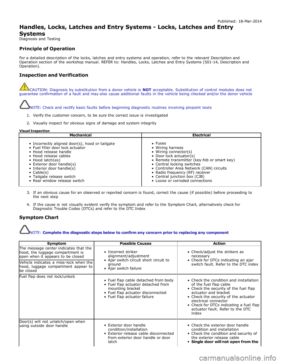
Published: 18-Mar-2014
Handles, Locks, Latches and Entry Systems - Locks, Latches and Entry Systems
Diagnosis and Testing
Principle of Operation
For a detailed description of the locks, latches and entry systems and operation, refer to the relevant Description and
Operation section of the workshop manual. REFER to: Handles, Locks, Latches and Entry Systems (501-14, Description and
Operation).
Inspection and Verification
CAUTION: Diagnosis by substitution from a donor vehicle is NOT acceptable. Substitution of control modules does not
guarantee confirmation of a fault and may also cause additional faults in the vehicle being checked and/or the donor vehicle
NOTE: Check and rectify basic faults before beginning diagnostic routines involving pinpoint tests
1. Verify the customer concern, to be sure the correct issue is investigated
2. Visually inspect for obvious signs of damage and system integrity
Visual Inspection
Mechanical Electrical
Incorrectly aligned door(s), hood or tailgate
Fuel filler door lock actuator
Hood release handle
Hood release cables
Hood latch(es)
Exterior door handle(s)
Interior door handle(s)
Cable(s)
Tailgate release switch
Rear window release switch
Fuses
Wiring harness
Wiring connector(s)
Door lock actuator(s)
Remote transmitter (key-fob or smart key)
Central locking switches
Controller Area Network (CAN) circuits
Radio frequency (RF) receiver
Central junction box (CJB)
Loose or corroded connections
3. If an obvious cause for an observed or reported concern is found, correct the cause (if possible) before proceeding to
the next step
4. If the cause is not visually evident verify the symptom and refer to the Symptom Chart, alternatively check for
Diagnostic Trouble Codes (DTCs) and refer to the DTC Index
Symptom Chart
NOTE: Complete the diagnostic steps below to confirm any concern prior to replacing any component
Symptom Possible Causes Action The message center indicates that the
hood, the luggage compartment is
open when it appears to be closed
Incorrect striker
alignment/adjustment
Ajar switch circuit short circuit to
ground
Ajar switch failure
Check/adjust the strikers as
necessary
Check for DTCs indicating an ajar
switch fault. Refer to the DTC index Vehicle indicates a miss-lock when the
hood, luggage compartment appear to
be closed Fuel flap does not lock/unlock
Fuel flap cable detached from body
Fuel flap actuator detached from
mounting bracket
Fuel flap actuator disconnected
Fuel flap actuator failure
Check the condition and installation
of the fuel flap cable
Check the security of the fuel flap
actuator and bracket
Check the security of the actuator
electrical connector
Check for DTCs indicating a fuel flap
actuator fault. Refer to the DTC
index Door(s) will not unlatch/open when
using outside door handle
Exterior door handle
condition/installation
Exterior release cable disconnected
from exterior door handle or door
latch
Check the exterior door handle
condition and installation
Check the condition and security of
the exterior release cable
Single door will not open from the
Page 2496 of 3039
Symptom Possible Causes Action outside (but opens from the
inside) GO to Pinpoint Test A. Door(s) will not unlatch/open when
using inside door handle
Child lock(s) engaged
Interior door handle
condition/installation
Interior release cable disconnected
from interior door handle or door
latch
Check that the child locks are
disengaged
Check the interior door handle
condition and installation
Check the condition and security of
the interior release cable
Single Door Will Not Open From
The Inside (but opens from the
outside) GO to Pinpoint Test B. Door(s) will not lock/unlock from key
fob, key or internal lock switch
Wiring harness/connectors
Central junction box (CJB)
Door lock switch
Cable fault
Check for relevant stored DTCs
Once any DTC related faults have
been rectified continue with the
diagnostic steps below
No lock / unlock function from
key-fob GO to Pinpoint Test C. Door ajar or miss lock signal at
message centre when door(s) are
closed or alarm triggering
Wiring harness
Instrument cluster
Incorrect striker
alignment/adjustment
Ajar switch circuit short circuit to
ground
Ajar switch failure
Latch Mounted Door Ajar Switch
Test GO to Pinpoint Test D. DTC Index
For a list of Diagnostic Trouble Codes (DTCs) that could be logged on this vehicle, please refer to Section 100-00.
REFER to: Communications Network (418-00, Diagnosis and Testing) /
Locks, Latches and Entry Systems - DTC: With (501-14, Diagnosis and Testing).
Pinpoint Test
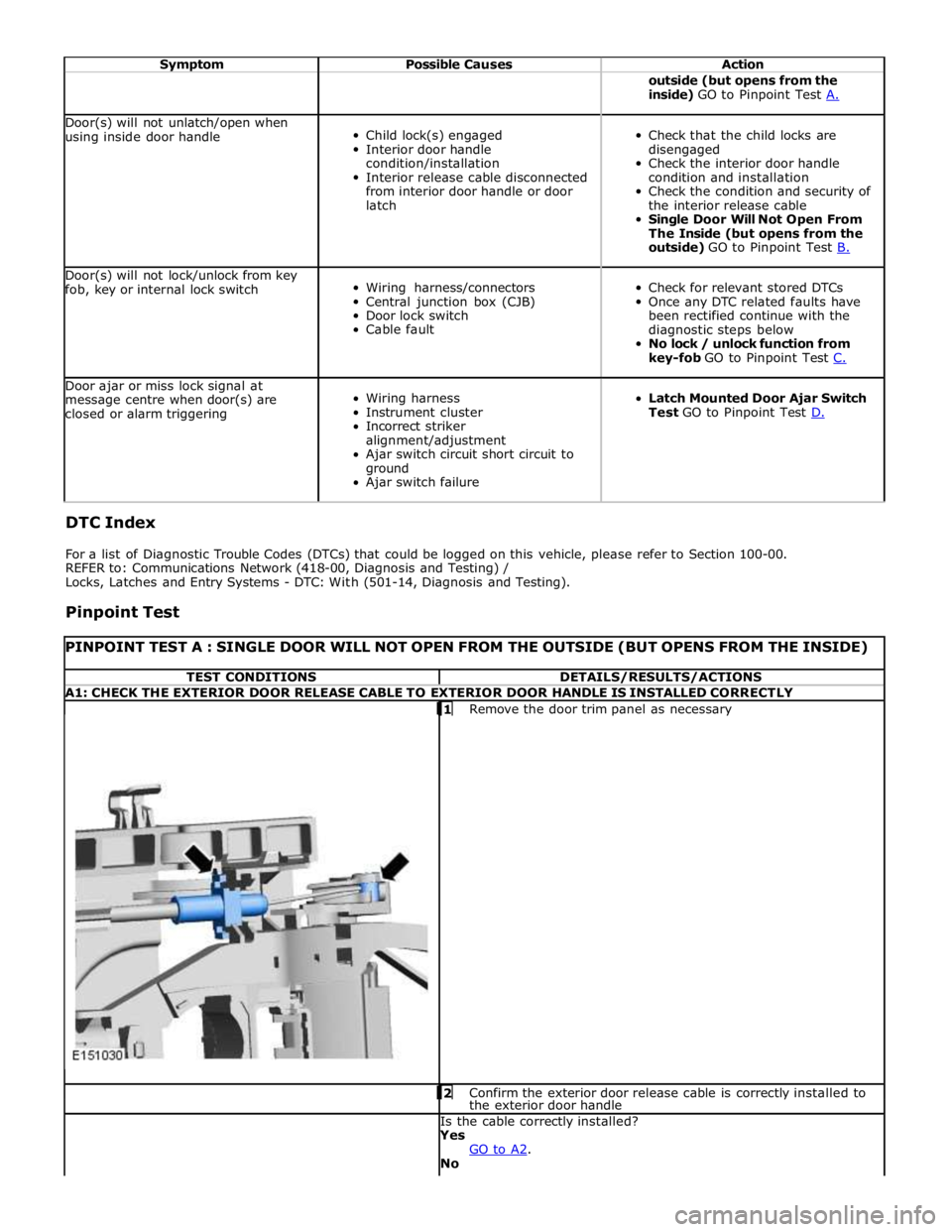
PINPOINT TEST A : SINGLE DOOR WILL NOT OPEN FROM THE OUTSIDE (BUT OPENS FROM THE INSIDE) TEST CONDITIONS DETAILS/RESULTS/ACTIONS A1: CHECK THE EXTERIOR DOOR RELEASE CABLE TO EXTERIOR DOOR HANDLE IS INSTALLED CORRECTLY
1 Remove the door trim panel as necessary 2 Confirm the exterior door release cable is correctly installed to the exterior door handle Is the cable correctly installed?
Yes
GO to A2. No
Page 2499 of 3039
NOTE: Test as a single component to ensure that the door latch is not replaced unnecessarily, when another component
may be at fault 1 Remove the door trim panel as necessary
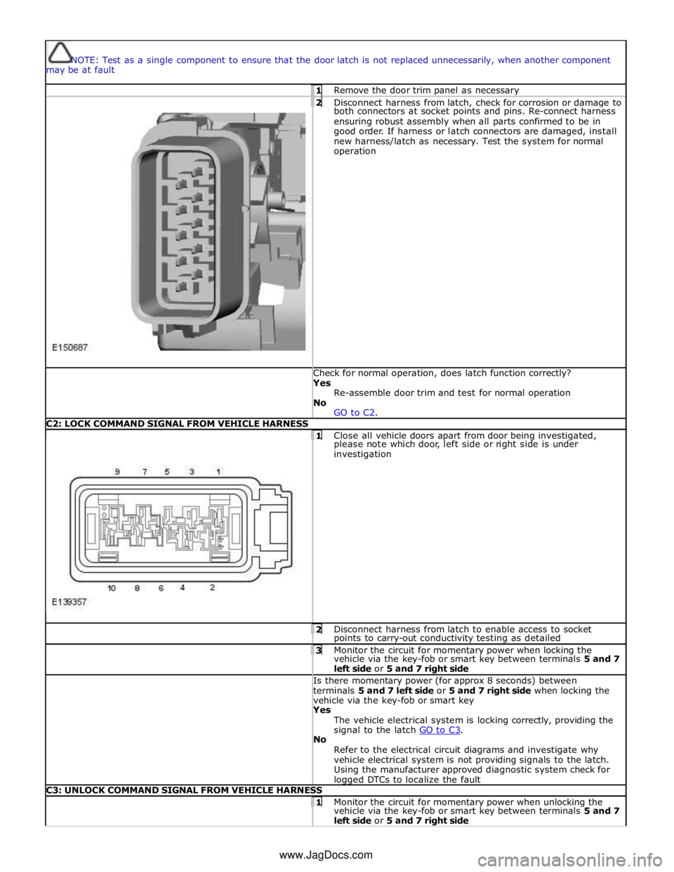
2 Disconnect harness from latch, check for corrosion or damage to both connectors at socket points and pins. Re-connect harness
ensuring robust assembly when all parts confirmed to be in
good order. If harness or latch connectors are damaged, install
new harness/latch as necessary. Test the system for normal
operation Check for normal operation, does latch function correctly? Yes
Re-assemble door trim and test for normal operation
No
GO to C2. C2: LOCK COMMAND SIGNAL FROM VEHICLE HARNESS
1 Close all vehicle doors apart from door being investigated, please note which door, left side or right side is under
investigation 2 Disconnect harness from latch to enable access to socket points to carry-out conductivity testing as detailed 3 Monitor the circuit for momentary power when locking the vehicle via the key-fob or smart key between terminals 5 and 7
left side or 5 and 7 right side Is there momentary power (for approx 8 seconds) between
terminals 5 and 7 left side or 5 and 7 right side when locking the
vehicle via the key-fob or smart key Yes
The vehicle electrical system is locking correctly, providing the
signal to the latch GO to C3. No
Refer to the electrical circuit diagrams and investigate why
vehicle electrical system is not providing signals to the latch.
Using the manufacturer approved diagnostic system check for logged DTCs to localize the fault C3: UNLOCK COMMAND SIGNAL FROM VEHICLE HARNESS 1 Monitor the circuit for momentary power when unlocking the vehicle via the key-fob or smart key between terminals 5 and 7
left side or 5 and 7 right side www.JagDocs.com
Page 2500 of 3039
Is there momentary power (for approx 8 seconds) between
terminals 5 and 7 left side and 5 and 7 right side when unlocking
the vehicle via the key-fob or smart key? Yes
The vehicle electrical system is unlocking correctly, providing
the signal to the latch GO to C4. No
Refer to the electrical circuit diagrams and investigate why
vehicle electrical system is not providing signals to the latch.
Using the manufacturer approved diagnostic system check for
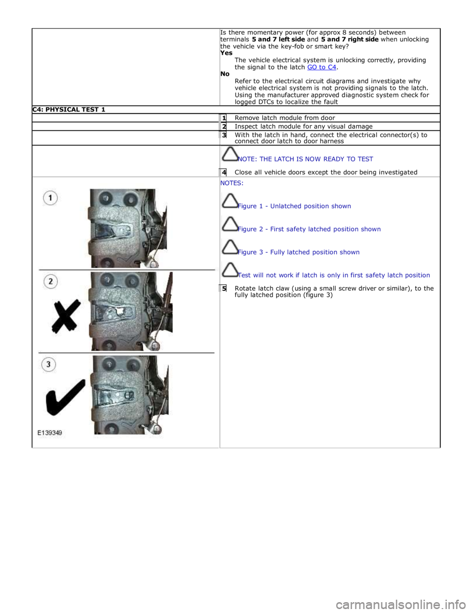
logged DTCs to localize the fault C4: PHYSICAL TEST 1 1 Remove latch module from door 2 Inspect latch module for any visual damage 3 With the latch in hand, connect the electrical connector(s) to connect door latch to door harness
NOTE: THE LATCH IS NOW READY TO TEST 4 Close all vehicle doors except the door being investigated NOTES:
Figure 1 - Unlatched position shown
Figure 2 - First safety latched position shown
Figure 3 - Fully latched position shown
Test will not work if latch is only in first safety latch position 5 Rotate latch claw (using a small screw driver or similar), to the fully latched position (figure 3)
Page 2501 of 3039
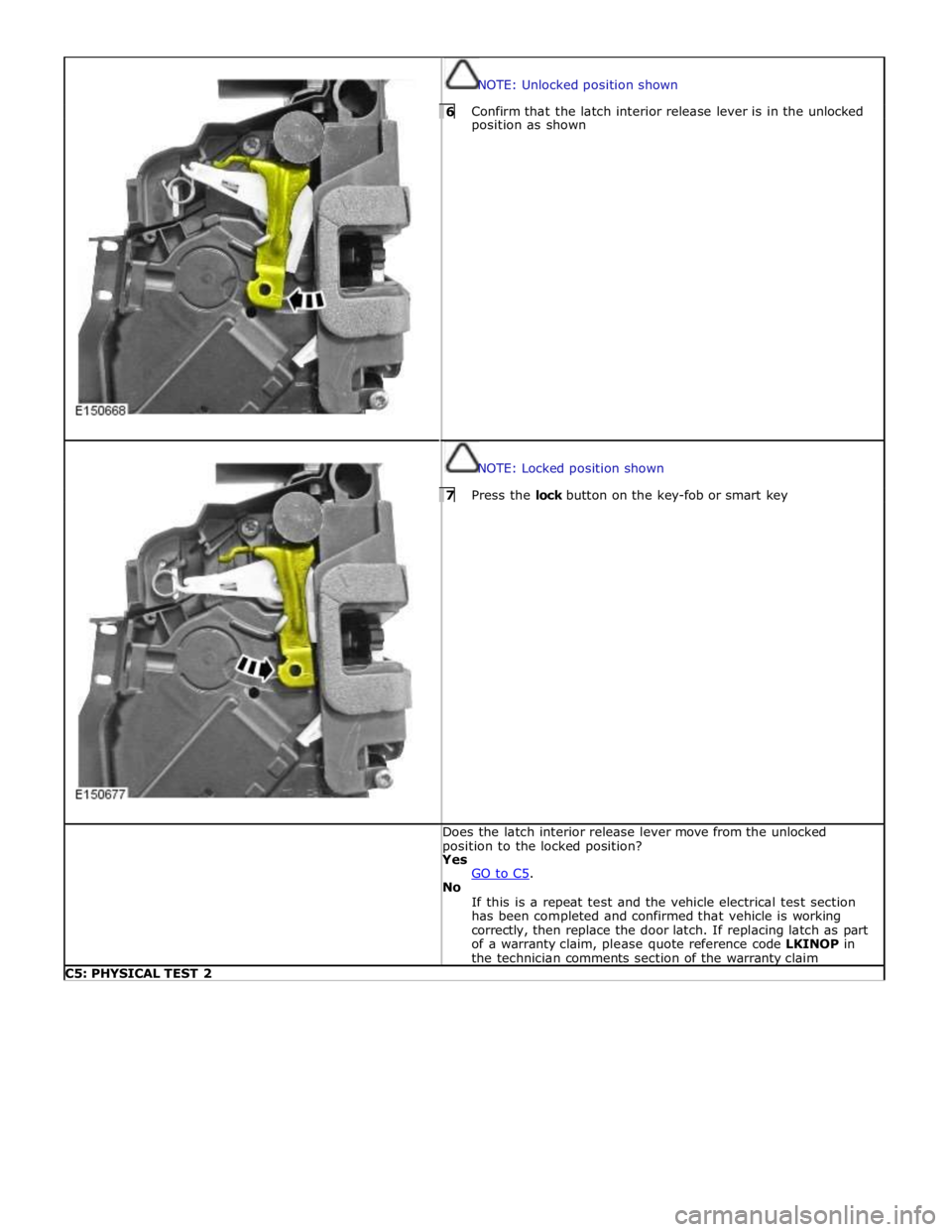
NOTE: Unlocked position shown 6 Confirm that the latch interior release lever is in the unlocked position as shown
NOTE: Locked position shown 7 Press the lock button on the key-fob or smart key Does the latch interior release lever move from the unlocked
position to the locked position? Yes
GO to C5. No
If this is a repeat test and the vehicle electrical test section
has been completed and confirmed that vehicle is working
correctly, then replace the door latch. If replacing latch as part
of a warranty claim, please quote reference code LKINOP in
the technician comments section of the warranty claim C5: PHYSICAL TEST 2
Page 2502 of 3039
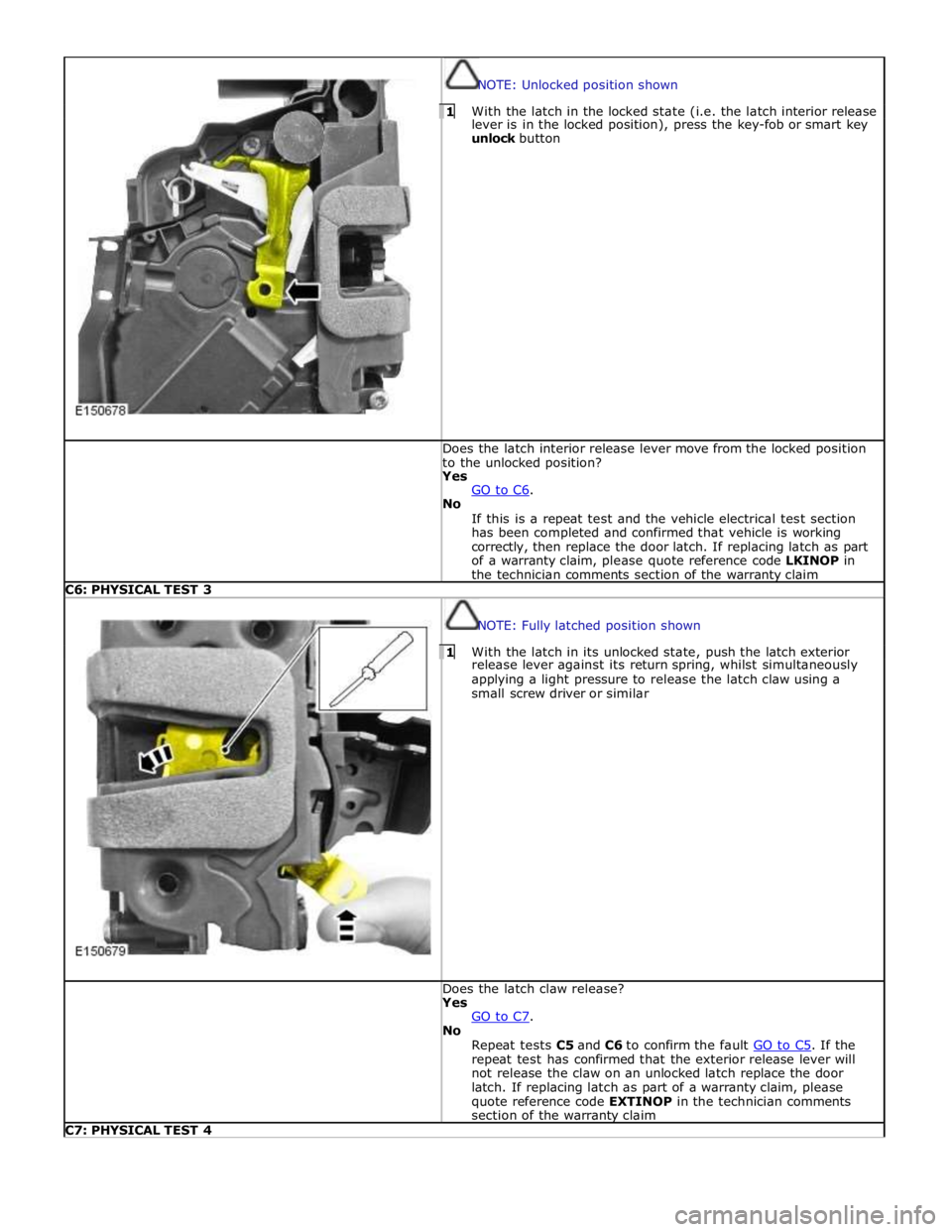
NOTE: Unlocked position shown 1 With the latch in the locked state (i.e. the latch interior release lever is in the locked position), press the key-fob or smart key
unlock button Does the latch interior release lever move from the locked position
to the unlocked position? Yes
GO to C6. No
If this is a repeat test and the vehicle electrical test section
has been completed and confirmed that vehicle is working
correctly, then replace the door latch. If replacing latch as part
of a warranty claim, please quote reference code LKINOP in
the technician comments section of the warranty claim C6: PHYSICAL TEST 3
NOTE: Fully latched position shown 1 With the latch in its unlocked state, push the latch exterior release lever against its return spring, whilst simultaneously
applying a light pressure to release the latch claw using a
small screw driver or similar Does the latch claw release? Yes
GO to C7. No
Repeat tests C5 and C6 to confirm the fault GO to C5. If the repeat test has confirmed that the exterior release lever will
not release the claw on an unlocked latch replace the door
latch. If replacing latch as part of a warranty claim, please
quote reference code EXTINOP in the technician comments
section of the warranty claim C7: PHYSICAL TEST 4