2010 JAGUAR XFR four wheel drive
[x] Cancel search: four wheel drivePage 777 of 3039

Steering Column - Steering Column - Overview
Description and Operation
OVERVIEW Published: 11-May-2011
The steering column comprises the upper column assembly, the lower column assembly and the steering wheel. The 3
components are positively connected together to pass driver rotary input from the steering wheel to a linear output of the
steering rack.
The upper column assembly contains electrical adjustment for steering wheel reach and rake, the electric steering lock
mechanism and the steering angle sensor. Steering adjustment memory positions are stored in the driver's seat module.
The electric steering column is a standard fitment on all models. The upper column assembly contains electrical adjustment for
steering wheel reach and rake, the electric column lock mechanism and the steering angle sensor. Steering adjustment memory
positions are stored in the driver's seat module. The column also features a 'tilt away' function which moves the steering
column away from the driver allowing easier exit and entry to the vehicle.
Column adjustment is provided by a single motor for both reach and rake adjustment. Operation of the column adjustment is
controlled by a four way joystick type switch located in the column lower shroud. Column adjustment is an integral part of the
driver position memory system.
www.JagDocs.com
Page 1362 of 3039
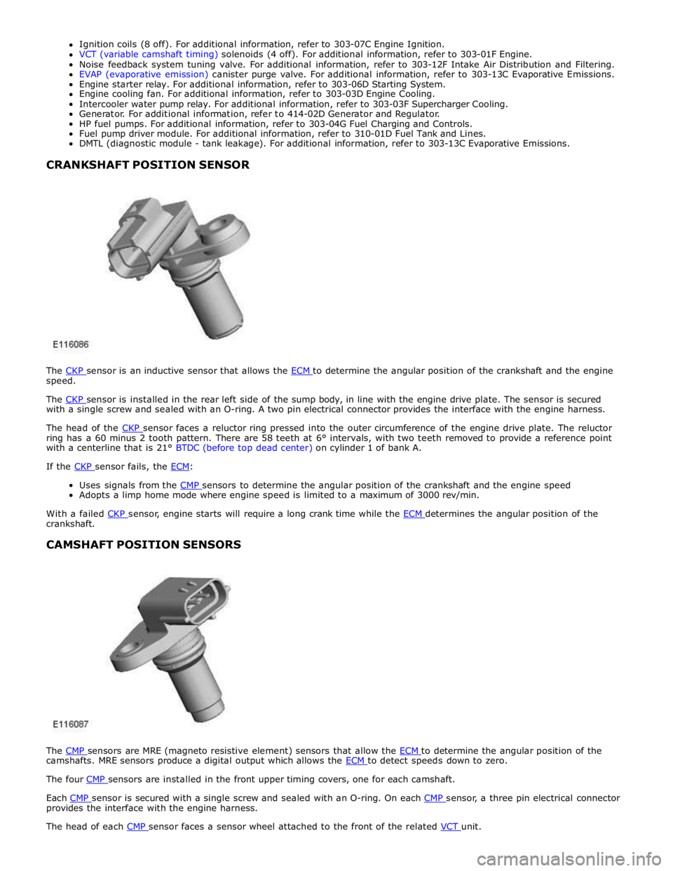
speed.
The CKP sensor is installed in the rear left side of the sump body, in line with the engine drive plate. The sensor is secured with a single screw and sealed with an O-ring. A two pin electrical connector provides the interface with the engine harness.
The head of the CKP sensor faces a reluctor ring pressed into the outer circumference of the engine drive plate. The reluctor ring has a 60 minus 2 tooth pattern. There are 58 teeth at 6° intervals, with two teeth removed to provide a reference point
with a centerline that is 21° BTDC (before top dead center) on cylinder 1 of bank A.
If the CKP sensor fails, the ECM:
Uses signals from the CMP sensors to determine the angular position of the crankshaft and the engine speed Adopts a limp home mode where engine speed is limited to a maximum of 3000 rev/min.
With a failed CKP sensor, engine starts will require a long crank time while the ECM determines the angular position of the crankshaft.
CAMSHAFT POSITION SENSORS
The CMP sensors are MRE (magneto resistive element) sensors that allow the ECM to determine the angular position of the camshafts. MRE sensors produce a digital output which allows the ECM to detect speeds down to zero. The four CMP sensors are installed in the front upper timing covers, one for each camshaft.
Each CMP sensor is secured with a single screw and sealed with an O-ring. On each CMP sensor, a three pin electrical connector provides the interface with the engine harness.
The head of each CMP sensor faces a sensor wheel attached to the front of the related VCT unit.
Page 1432 of 3039
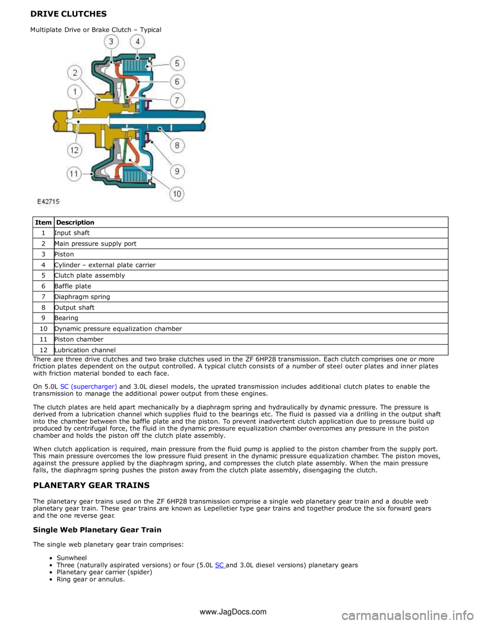
DRIVE CLUTCHES
Item Description 1 Input shaft 2 Main pressure supply port 3 Piston 4 Cylinder – external plate carrier 5 Clutch plate assembly 6 Baffle plate 7 Diaphragm spring 8 Output shaft 9 Bearing 10 Dynamic pressure equalization chamber 11 Piston chamber 12 Lubrication channel There are three drive clutches and two brake clutches used in the ZF 6HP28 transmission. Each clutch comprises one or more
friction plates dependent on the output controlled. A typical clutch consists of a number of steel outer plates and inner plates
with friction material bonded to each face.
On 5.0L SC (supercharger) and 3.0L diesel models, the uprated transmission includes additional clutch plates to enable the
transmission to manage the additional power output from these engines.
The clutch plates are held apart mechanically by a diaphragm spring and hydraulically by dynamic pressure. The pressure is
derived from a lubrication channel which supplies fluid to the bearings etc. The fluid is passed via a drilling in the output shaft
into the chamber between the baffle plate and the piston. To prevent inadvertent clutch application due to pressure build up
produced by centrifugal force, the fluid in the dynamic pressure equalization chamber overcomes any pressure in the piston
chamber and holds the piston off the clutch plate assembly.
When clutch application is required, main pressure from the fluid pump is applied to the piston chamber from the supply port.
This main pressure overcomes the low pressure fluid present in the dynamic pressure equalization chamber. The piston moves,
against the pressure applied by the diaphragm spring, and compresses the clutch plate assembly. When the main pressure
falls, the diaphragm spring pushes the piston away from the clutch plate assembly, disengaging the clutch.
PLANETARY GEAR TRAINS
The planetary gear trains used on the ZF 6HP28 transmission comprise a single web planetary gear train and a double web
planetary gear train. These gear trains are known as Lepelletier type gear trains and together produce the six forward gears
and the one reverse gear.
Single Web Planetary Gear Train
The single web planetary gear train comprises:
Sunwheel
Three (naturally aspirated versions) or four (5.0L SC and 3.0L diesel versions) planetary gears Planetary gear carrier (spider)
Ring gear or annulus. Multiplate Drive or Brake Clutch – Typical www.JagDocs.com
Page 1641 of 3039
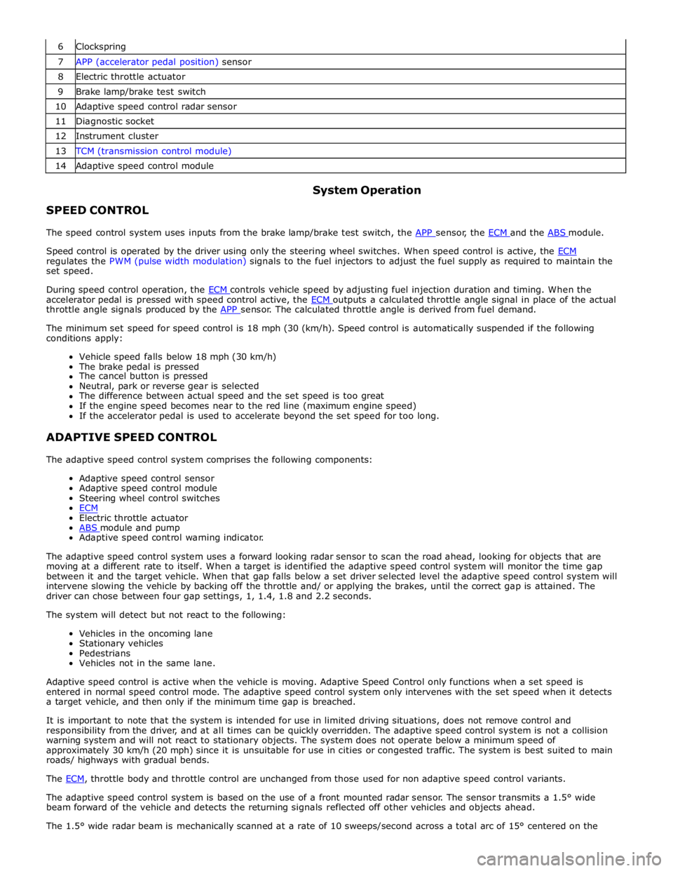
6 Clockspring 7 APP (accelerator pedal position) sensor 8 Electric throttle actuator 9 Brake lamp/brake test switch 10 Adaptive speed control radar sensor 11 Diagnostic socket 12 Instrument cluster 13 TCM (transmission control module) 14 Adaptive speed control module
SPEED CONTROL System Operation
The speed control system uses inputs from the brake lamp/brake test switch, the APP sensor, the ECM and the ABS module.
Speed control is operated by the driver using only the steering wheel switches. When speed control is active, the ECM regulates the PWM (pulse width modulation) signals to the fuel injectors to adjust the fuel supply as required to maintain the
set speed.
During speed control operation, the ECM controls vehicle speed by adjusting fuel injection duration and timing. When the accelerator pedal is pressed with speed control active, the ECM outputs a calculated throttle angle signal in place of the actual throttle angle signals produced by the APP sensor. The calculated throttle angle is derived from fuel demand.
The minimum set speed for speed control is 18 mph (30 (km/h). Speed control is automatically suspended if the following
conditions apply:
Vehicle speed falls below 18 mph (30 km/h)
The brake pedal is pressed
The cancel button is pressed
Neutral, park or reverse gear is selected
The difference between actual speed and the set speed is too great
If the engine speed becomes near to the red line (maximum engine speed)
If the accelerator pedal is used to accelerate beyond the set speed for too long.
ADAPTIVE SPEED CONTROL
The adaptive speed control system comprises the following components:
Adaptive speed control sensor
Adaptive speed control module
Steering wheel control switches
ECM
Electric throttle actuator
ABS module and pump Adaptive speed control warning indicator.
The adaptive speed control system uses a forward looking radar sensor to scan the road ahead, looking for objects that are
moving at a different rate to itself. When a target is identified the adaptive speed control system will monitor the time gap
between it and the target vehicle. When that gap falls below a set driver selected level the adaptive speed control system will
intervene slowing the vehicle by backing off the throttle and/ or applying the brakes, until the correct gap is attained. The
driver can chose between four gap settings, 1, 1.4, 1.8 and 2.2 seconds.
The system will detect but not react to the following:
Vehicles in the oncoming lane
Stationary vehicles
Pedestrians
Vehicles not in the same lane.
Adaptive speed control is active when the vehicle is moving. Adaptive Speed Control only functions when a set speed is
entered in normal speed control mode. The adaptive speed control system only intervenes with the set speed when it detects
a target vehicle, and then only if the minimum time gap is breached.
It is important to note that the system is intended for use in limited driving situations, does not remove control and
responsibility from the driver, and at all times can be quickly overridden. The adaptive speed control system is not a collision
warning system and will not react to stationary objects. The system does not operate below a minimum speed of
approximately 30 km/h (20 mph) since it is unsuitable for use in cities or congested traffic. The system is best suited to main
roads/ highways with gradual bends.
The ECM, throttle body and throttle control are unchanged from those used for non adaptive speed control variants.
The adaptive speed control system is based on the use of a front mounted radar sensor. The sensor transmits a 1.5° wide
beam forward of the vehicle and detects the returning signals reflected off other vehicles and objects ahead.
The 1.5° wide radar beam is mechanically scanned at a rate of 10 sweeps/second across a total arc of 15° centered on the
Page 1822 of 3039
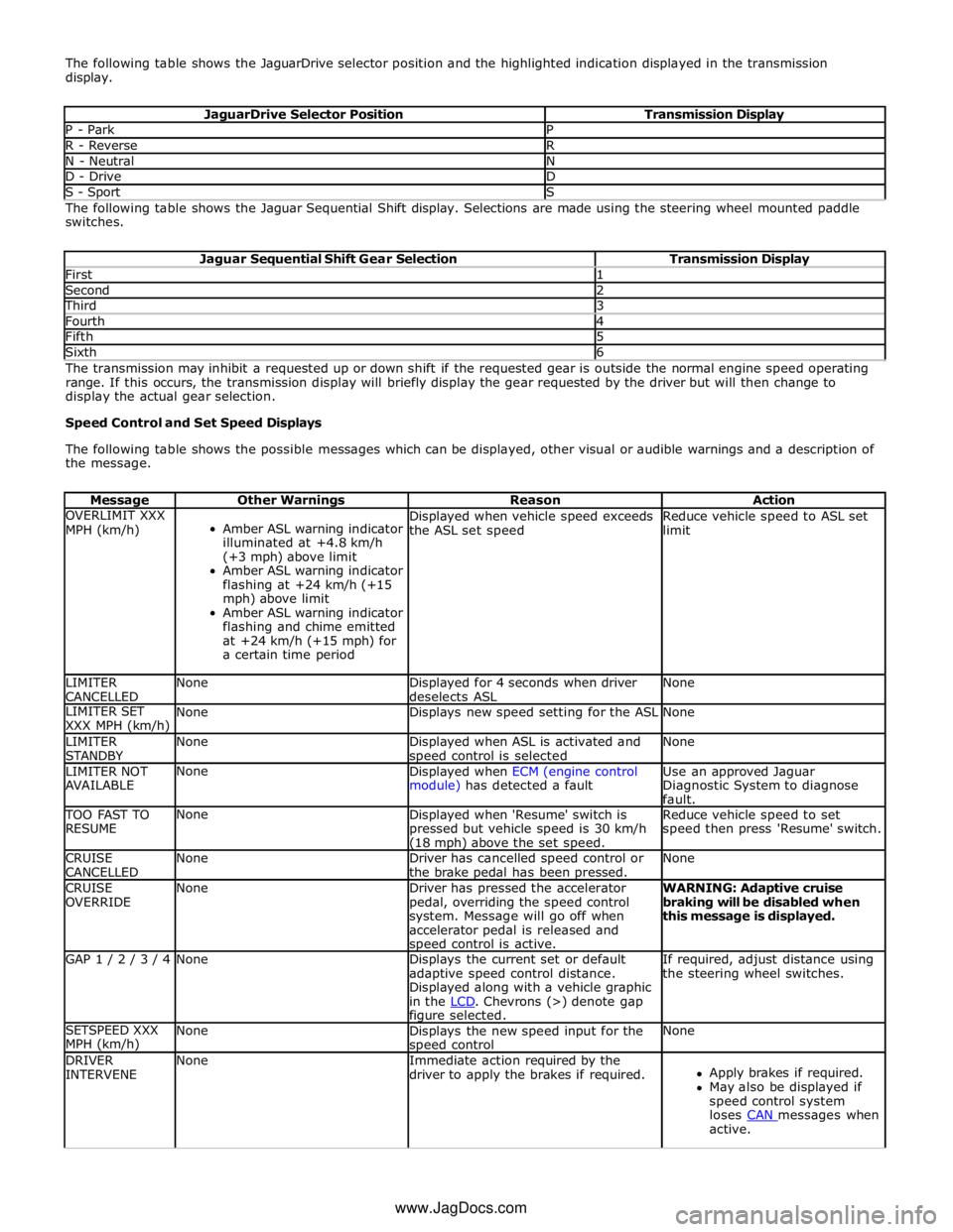
The following table shows the JaguarDrive selector position and the highlighted indication displayed in the transmission
display.
JaguarDrive Selector Position Transmission Display P - Park P R - Reverse R N - Neutral N D - Drive D S - Sport S The following table shows the Jaguar Sequential Shift display. Selections are made using the steering wheel mounted paddle
switches.
Jaguar Sequential Shift Gear Selection Transmission Display First 1 Second 2 Third 3 Fourth 4 Fifth 5 Sixth 6 The transmission may inhibit a requested up or down shift if the requested gear is outside the normal engine speed operating
range. If this occurs, the transmission display will briefly display the gear requested by the driver but will then change to
display the actual gear selection.
Speed Control and Set Speed Displays
The following table shows the possible messages which can be displayed, other visual or audible warnings and a description of
the message.
Message Other Warnings Reason Action OVERLIMIT XXX
MPH (km/h)
Amber ASL warning indicator
illuminated at +4.8 km/h
(+3 mph) above limit
Amber ASL warning indicator
flashing at +24 km/h (+15
mph) above limit
Amber ASL warning indicator
flashing and chime emitted
at +24 km/h (+15 mph) for
a certain time period Displayed when vehicle speed exceeds
the ASL set speed Reduce vehicle speed to ASL set
limit LIMITER
CANCELLED None
Displayed for 4 seconds when driver
deselects ASL None LIMITER SET
XXX MPH (km/h) None Displays new speed setting for the ASL None LIMITER
STANDBY None
Displayed when ASL is activated and speed control is selected None LIMITER NOT
AVAILABLE None
Displayed when ECM (engine control
module) has detected a fault Use an approved Jaguar
Diagnostic System to diagnose
fault. TOO FAST TO
RESUME None
Displayed when 'Resume' switch is
pressed but vehicle speed is 30 km/h (18 mph) above the set speed. Reduce vehicle speed to set
speed then press 'Resume' switch. CRUISE
CANCELLED None
Driver has cancelled speed control or
the brake pedal has been pressed. None CRUISE
OVERRIDE None
Driver has pressed the accelerator
pedal, overriding the speed control
system. Message will go off when
accelerator pedal is released and speed control is active. WARNING: Adaptive cruise
braking will be disabled when
this message is displayed. GAP 1 / 2 / 3 / 4 None
Displays the current set or default
adaptive speed control distance.
Displayed along with a vehicle graphic
in the LCD. Chevrons (>) denote gap figure selected. If required, adjust distance using
the steering wheel switches. SETSPEED XXX
MPH (km/h) None
Displays the new speed input for the speed control None DRIVER
INTERVENE None
Immediate action required by the
driver to apply the brakes if required.
Apply brakes if required.
May also be displayed if
speed control system
loses CAN messages when active. www.JagDocs.com
Page 1951 of 3039
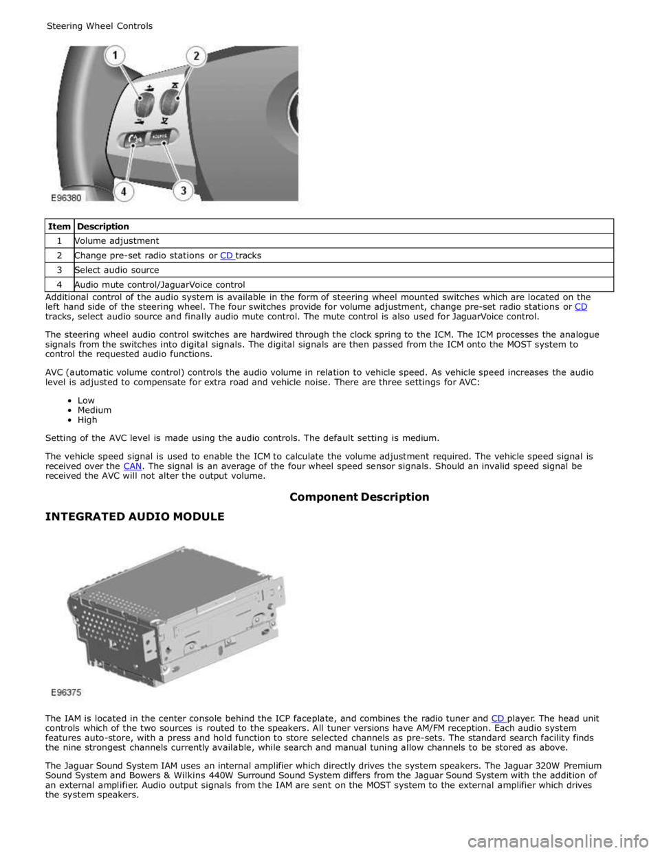
1 Volume adjustment 2 Change pre-set radio stations or CD tracks 3 Select audio source 4 Audio mute control/JaguarVoice control Additional control of the audio system is available in the form of steering wheel mounted switches which are located on the
left hand side of the steering wheel. The four switches provide for volume adjustment, change pre-set radio stations or CD tracks, select audio source and finally audio mute control. The mute control is also used for JaguarVoice control.
The steering wheel audio control switches are hardwired through the clock spring to the ICM. The ICM processes the analogue
signals from the switches into digital signals. The digital signals are then passed from the ICM onto the MOST system to
control the requested audio functions.
AVC (automatic volume control) controls the audio volume in relation to vehicle speed. As vehicle speed increases the audio
level is adjusted to compensate for extra road and vehicle noise. There are three settings for AVC:
Low
Medium
High
Setting of the AVC level is made using the audio controls. The default setting is medium.
The vehicle speed signal is used to enable the ICM to calculate the volume adjustment required. The vehicle speed signal is
received over the CAN. The signal is an average of the four wheel speed sensor signals. Should an invalid speed signal be received the AVC will not alter the output volume.
INTEGRATED AUDIO MODULE Component Description
The IAM is located in the center console behind the ICP faceplate, and combines the radio tuner and CD player. The head unit controls which of the two sources is routed to the speakers. All tuner versions have AM/FM reception. Each audio system
features auto-store, with a press and hold function to store selected channels as pre-sets. The standard search facility finds
the nine strongest channels currently available, while search and manual tuning allow channels to be stored as above.
The Jaguar Sound System IAM uses an internal amplifier which directly drives the system speakers. The Jaguar 320W Premium
Sound System and Bowers & Wilkins 440W Surround Sound System differs from the Jaguar Sound System with the addition of
an external amplifier. Audio output signals from the IAM are sent on the MOST system to the external amplifier which drives
the system speakers.
Page 2616 of 3039
and the safety belt buckle sensor. Based on this data, the RCM decides which level of airbag module deployment is required and forwards the information to the second area, the deployment handler.
The deployment handler evaluates the status of the seat track position sensor and safety belt buckle sensors before a decision
is made about which restraints should finally be deployed.
Data from the side crash sensors is used by the RCM in conjunction with acceleration data from the RCM internal accelerometer to make a deployment decision. The RCM processes the acceleration data and subject to an impact being of high enough severity, decides whether the side airbag module should be deployed.
On board testing of the airbag modules, front safety belt pretensioner firing circuits, warning indicator circuits and module
status (the crash and side impact sensors perform basic self-tests) is performed by the RCM together with the storing of fault codes.
The RCM drives the SRS indicator on the instrument pack via a CAN signal. If the warning lamp fails, a fault code is recorded and a warning tone is sounded in place of the lamp if a further fault occurs. It also provides a temporary back-up power supply
to operate the airbag modules in the event that in crash conditions, the battery supply is lost. In the event of a crash, it
records certain data which can be accessed via the diagnostic connector.
A safing sensor in the RCM provides confirmation of an impact to verify if airbag and pretensioner activation is necessary. A roll-over sensor monitors the lateral attitude of the vehicle. Various firing strategies are employed by the RCM to ensure that during an accident only the appropriate airbags and pretensioners are fired. The firing strategy used also depends on the
inputs from the safety belt switches and the occupant monitoring system.
An energy reserve in the RCM ensures there is always a minimum of 150 milliseconds of stored energy available if the power supply from the ignition switch is disrupted during a crash. The stored energy is sufficient to produce firing signals for the
driver airbag, the passenger airbag and the safety belt pretensioners.
When the ignition is switched on, the RCM performs a self-test and then performs cyclical monitoring of the system. If a fault is detected the RCM stores a related fault code and illuminates the airbag warning indicator. The faults can be retrieved by the recommended Jaguar diagnostic tool over the CAN bus. If a fault that could cause a false fire signal is detected, the RCM disables the respective firing circuit, and keeps it disabled during a crash event.
Clock Spring
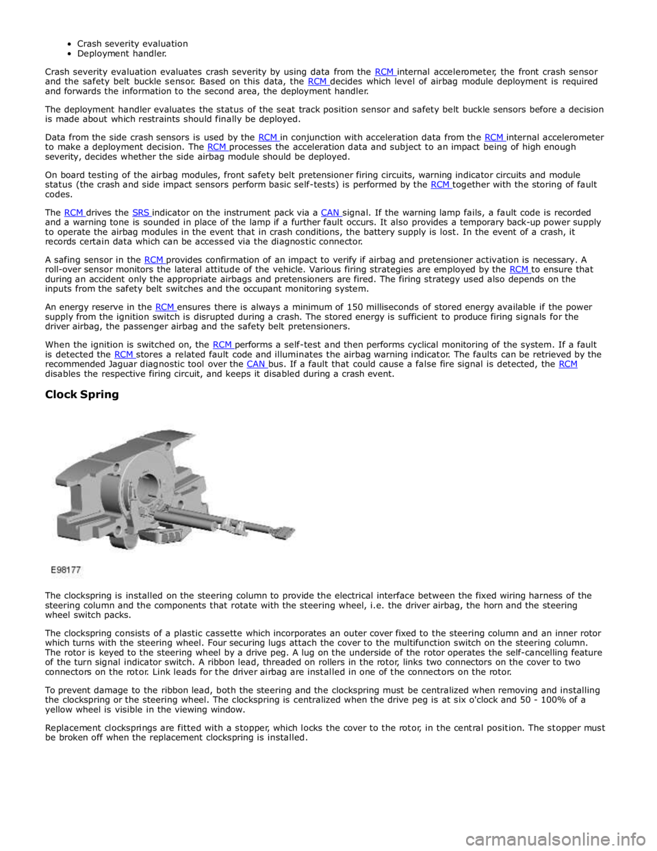
The clockspring is installed on the steering column to provide the electrical interface between the fixed wiring harness of the
steering column and the components that rotate with the steering wheel, i.e. the driver airbag, the horn and the steering
wheel switch packs.
The clockspring consists of a plastic cassette which incorporates an outer cover fixed to the steering column and an inner rotor
which turns with the steering wheel. Four securing lugs attach the cover to the multifunction switch on the steering column.
The rotor is keyed to the steering wheel by a drive peg. A lug on the underside of the rotor operates the self-cancelling feature
of the turn signal indicator switch. A ribbon lead, threaded on rollers in the rotor, links two connectors on the cover to two
connectors on the rotor. Link leads for the driver airbag are installed in one of the connectors on the rotor.
To prevent damage to the ribbon lead, both the steering and the clockspring must be centralized when removing and installing
the clockspring or the steering wheel. The clockspring is centralized when the drive peg is at six o'clock and 50 - 100% of a
yellow wheel is visible in the viewing window.
Replacement clocksprings are fitted with a stopper, which locks the cover to the rotor, in the central position. The stopper must
be broken off when the replacement clockspring is installed.