2010 JAGUAR XFR center console
[x] Cancel search: center consolePage 1953 of 3039

7 Triple TV antenna module 8 RF filter The diversity antenna module, located on the left hand side of the heated rear window, receives signals from four antennas
located in the heated rear window, where one antenna is dedicated as an AM antenna.
The diversity tuning system ensures that the strongest signals are used by the radio system to ensure the best possible FM
reception. Using the three remaining receiving antennas serves to eliminate multipath signal distortion. Typically, the signal
from the antenna with the least noise is chosen, and the other antennas are ignored.
The diversity antenna module is an interface between the antenna aerials in the heated rear window and audio system
modules/tuners. It provides antenna signals to the AM/FM tuner in the IAM, to the DAB receiver and to the VICS (vehicle
information and communication systems) or TMC (traffic message channel) in the navigation computer.
There are three different types of diversity antenna module fitted depending on the vehicle market and infotainment
equipment specification:
AM/FM with one co-axial output
AM/FM and VICS/TMC with two co-axial outputs
AM/FM, VICS/TMC and DAB band III with three co-axial outputs
The diversity antenna module receives a power supply from the IAM.
Vehicle or other component generated electromagnetic interference may cause unwanted disturbances in the radio and TV
reception signals. The disturbance may interrupt, obstruct, or otherwise degrade or limit the effective performance of the
circuit. It frequently affects the reception of AM radio in urban areas and can also affect FM radio and television reception,
although to a lesser extent.
The RF filters, which act as RF isolators, are located on both sides of the heated rear window and are used to reduce the
electromagnetic interference. The left hand side RF filter is connected across the heated rear window power supply and used to
separate the DC (direct current) interference from the RF signals. The right hand side RF filter is used in conjunction with the
TV antenna module (if fitted). If the TV system is not fitted the filter is linked directly to ground.
INFORMATION CONTROL MODULE
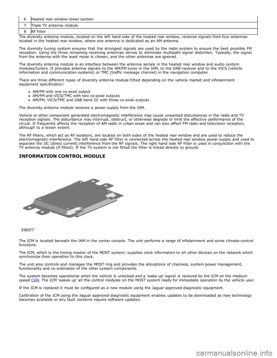
The ICM is located beneath the IAM in the center console. The unit performs a range of infotainment and some climate-control
functions.
The ICM, which is the timing master of the MOST system; supplies clock information to all other devices on the network which
synchronize their operation to this clock.
The unit also controls and manages the MOST ring and provides the allocations of channels, system power management,
functionality and co-ordination of the other system components.
The system becomes operational when the vehicle is unlocked and a 'wake up' signal is received by the ICM on the medium
speed CAN. The ICM 'wakes up' all the control modules on the MOST system ready for immediate operation by the vehicle user. If the ICM is replaced it must be configured as a new module using the Jaguar approved diagnostic equipment.
Calibration of the ICM using the Jaguar approved diagnostic equipment enables updates to be downloaded as new technology
becomes available or any fault concerns require software updates.
Page 1955 of 3039

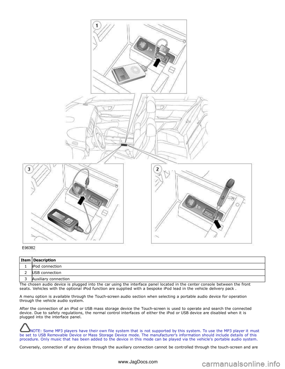
Item Description 1 iPod connection 2 USB connection 3 Auxiliary connection The chosen audio device is plugged into the car using the interface panel located in the center console between the front
seats. Vehicles with the optional iPod function are supplied with a bespoke iPod lead in the vehicle delivery pack .
A menu option is available through the Touch-screen audio section when selecting a portable audio device for operation
through the vehicle audio system.
After the connection of an iPod or USB mass storage device the Touch-screen is used to operate and search the connected
device. Due to safety regulations, the normal control interfaces of either the iPod or USB device are disabled when it is
plugged into the interface panel.
NOTE: Some MP3 players have their own file system that is not supported by this system. To use the MP3 player it must
be set to USB Removable Device or Mass Storage Device mode. The manufacturer's information should include details of this
procedure. Only music that has been added to the device in this mode can be played via the vehicle's portable audio system.
Conversely, connection of any devices through the auxiliary connection cannot be controlled through the touch-screen and are www.JagDocs.com
Page 2172 of 3039

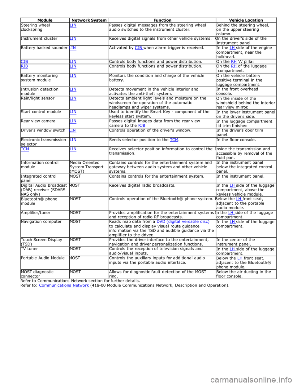
Module Network System Function Vehicle Location
Steering wheel
clockspring LIN Passes digital messages from the steering wheel
audio switches to the instrument cluster. Behind the steering wheel,
on the upper steering
column.
Instrument cluster LIN Receives digital signals from other vehicle systems. On the driver's side of the
instrument panel.
Battery backed sounder LIN Activated by CJB when alarm trigger is received. In the LH side of the engine compartment, near the
bulkhead.
CJB LIN Controls body functions and power distribution. On the RH 'A' pillar.
RJB LIN Controls body functions and power distribution. On the RH of the luggage compartment.
Battery monitoring
system module
Intrusion detection
module LIN Monitors the condition and charge of the vehicle
battery.
LIN Detects movement in the vehicle interior and
activates the anti-theft system. On the vehicle battery
positive terminal in the
luggage compartment.
In the front overhead
console.
Rain/light sensor LIN Detects ambient light levels and moisture on the
windscreen for operation of the automatic
headlamps and wiper systems.
Start control module LIN Used to identify the Smart Key - component of the
keyless start system.
Rear view camera LIN Passes digital images data from the rear view
camera to the RJB On the inside of the
windshield behind the interior
rear view mirror.
In the lower instrument panel
on the driver's side.
In the luggage compartment
lid trim finisher.
Driver's window switch LIN Controls operation of the driver's window. In the driver's door trim
panel.
Electronic transmission
selector LIN Sends selector position to the TCM. In the floor console. TCM LIN Receives selector position information to control the Inside the transmission and
Information control
module
Media Oriented
System Transport
(MOST) transmission.
Contains controls for the entertainment system and
gateway between audio system and other vehicle
systems. accessible by removal of the
fluid pan.
In the instrument panel
below the integrated control
panel.
Integrated control
panel MOST Contains controls for the entertainment system. In the instrument panel.
Digital Audio Broadcast MOST Receives digital radio broadcasts. In the LH side of the luggage (DAB) receiver (SDARS
NAS only)
Bluetooth® phone
module compartment, above the
keyless vehicle module.
MOST Controls operation of the Bluetooth® phone system. Below the LH front seat, adjacent to the portable
audio module.
Amplifier/tuner MOST Provides amplification for the entertainment systems In the LH side of the luggage and reception of radio RF broadcasts.
Navigation computer MOST Reads map data from a DVD (digital versatile disc)
to calculate and display visual route guidance
information via the TSD and audible guidance via the
amplifier to the driver. compartment.
In the LH side of the luggage compartment.
Touch Screen Display
(TSD) MOST Provides the driver interface to the entertainment,
navigation and driver personalization functions. In the center of the
instrument panel.
TV tuner MOST Controls the reception of television signals and
audio/visual inputs.
Portable Audio Module MOST Controls the auxiliary inputs for additional audio
inputs via the portable audio interface. In the LH side of the luggage compartment.
Below the LH front seat, adjacent to the Bluetooth®
phone module.
MOST diagnostic
connector MOST Allows for diagnostic fault detection of the MOST
ring. Below the air ducting in the
floor console.
Refer to Communications Network section for further details.
Refer to: Communications Network (418-00 Module Communications Network, Description and Operation).
Page 2469 of 3039

Instrument Panel and Console - Instrument Panel Console
Removal and Installation Published: 11-May-2011
Removal
CAUTIONS:
Inspect the seals, replace if damaged.
Inspect the O-rings, replace if damaged.
NOTE: Removal steps in this procedure may contain installation details.
All vehicles
1. Refer to: Battery Disconnect and Connect (414-01 Battery, Mounting and Cables, General Procedures).
2. WARNING: Make sure to support the vehicle with axle stands.
Raise and support the vehicle.
Vehicles with supercharger
3. Refer to: Cooling System Draining, Filling and Bleeding - V8 S/C 5.0L Petrol (303-03C Engine Cooling - V8 5.0L Petrol/V8 S/C 5.0L Petrol, General Procedures).
Vehicles without supercharger
4. Refer to: Cooling System Draining, Filling and Bleeding - V8 5.0L Petrol (303-03C Engine Cooling - V8 5.0L Petrol/V8 S/C 5.0L Petrol, General
Procedures).
Vehicles with diesel engine
5. Refer to: Cooling System Draining, Filling and Bleeding (303-03A Engine Cooling - TDV6 3.0L Diesel, General Procedures).
All vehicles
6. Refer to: Air Conditioning (A/C) System Recovery, Evacuation and Charging (412-00 Climate Control System - General Information, General Procedures).
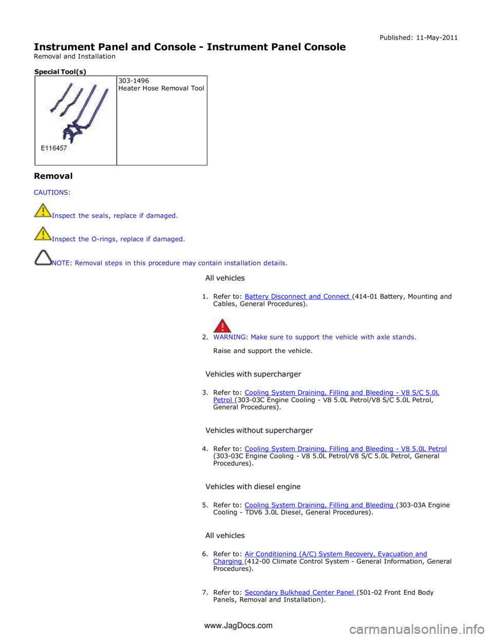
7. Refer to: Secondary Bulkhead Center Panel (501-02 Front End Body Panels, Removal and Installation). 303-1496
Heater Hose Removal Tool Special Tool(s)
www.JagDocs.com