2010 JAGUAR XFR Transmission
[x] Cancel search: TransmissionPage 1447 of 3039

DTC Description Possible Cause Action U0103-82
Lost Communication With
Gear Shift Control Module
A-alive / sequence counter
incorrect / not updated
Alive counter fault Check Transmission shift module for stored DTCs.
Check CAN Bus Circuit for fault U0103-83
Lost Communication With
Gear Shift Control Module A
- value of signal protection
calculation incorrect
Checksum fault Check Transmission shift module for stored DTCs.
Check CAN Bus Circuit for fault U0103-87
Lost Communication With
Gear Shift Control Module A
- missing message
CAN Timeout Check Transmission shift module for stored DTCs.
Check CAN Bus Circuit for fault U0122-82
Lost Communication With
Vehicle Dynamics Control
Module - alive / sequence
counter incorrect / not updated
Alive counter fault Check Anti-lock braking system for stored DTCs. Check
CAN Bus Circuit for fault U0122-83
Lost Communication With
Vehicle Dynamics Control
Module - value of signal
protection calculation
incorrect
Checksum fault Check Anti-lock braking system for stored DTCs. Check
CAN Bus Circuit for fault U0122-87
Lost Communication With
Vehicle Dynamics Control
Module - missing message
CAN Timeout Check Anti-lock braking system for stored DTCs. Check
CAN Bus Circuit for fault U0126-00
Lost Communication With
Steering Angle Sensor
Module - no sub type
information
Lost Communication
With Steering Angle
Sensor Module Check Steering angle sensor for stored DTCs. Check
CAN Bus Circuit for fault U0128-87
Lost Communication With
Park Brake Control Module -
missing message
CAN timeout electronic
parking brake module Check Electronic Parking Brake Module for stored DTCs.
Check CAN Bus Circuit for fault U0140-82
Lost Communication With
Body Control Module - alive / sequence counter incorrect / not updated
Alive counter fault Check Central junction box for stored DTCs. Check CAN
Bus Circuit for fault U0140-83
Lost Communication With
Body Control Module - value
of signal protection
calculation incorrect
Checksum fault Check Central junction box for stored DTCs. Check CAN
Bus Circuit for fault U0140-87
Lost Communication With
Body Control Module - missing message
CAN Timeout Check Central junction box for stored DTCs. Check CAN
Bus Circuit for fault U0155-87
Lost Communication With
Instrument Panel Cluster
(Instrument cluster) Control
Module - missing message
CAN timeout instrument
cluster Check Instrument cluster for stored DTCs. Check CAN
Bus Circuit for fault U0300-68
Control Module - event
information
Transmission software
does not match vehicle
network Check Central junction box software level, Check
Transmission control module Software level, Update
software as required using the manufacturer approved
process U0401-08
Invalid Data Received From
Engine control module/PCM
A - Bus Signal Message
Failures
Inaccurate engine speed,
torque information Check Engine control module for stored DTCs, Check
CAN Bus circuit for faults U0401-68
Invalid Data Received from
Engine control module/PCM
A - event information
Inaccurate engine speed,
torque information Check Engine control module for stored DTCs. Check
CAN Bus Circuit for fault U0401-86
Invalid Data Received from
Engine control module/PCM
A - Signal Invalid
Inaccurate engine speed,
torque information Check Engine control module for stored DTCs. Check
CAN Bus Circuit for fault U0404-68
Invalid Data Received from
Gear Shift Control Module A
- event information
Incorrect CAN data
received from
Transmission shift
module Check Transmission Shift Module for stored DTCs.
Refer to Circuit diagrams and check CAN and LIN Bus
for Circuit fault U0404-81
Invalid Data Received from
Gear Shift Control Module A
- Invalid Serial Data
Received
Incorrect LIN data
received from
Transmission shift
module Check Transmission Shift Module for stored DTCs.
Refer to Circuit diagrams and check CAN and LIN Bus
for Circuit fault www.JagDocs.com
Page 1448 of 3039

DTC Description Possible Cause Action U0416-68
Invalid Data Received From
Vehicle Dynamics Control
Module - event information
Event information brake
information Check Engine control module for stored DTCs. Check
CAN Bus Circuit for fault U0422-68
Invalid Data Received From
Body Control Module - event
information
Event information invalid
Power mode information Check Central junction box for stored DTCs. Check CAN
Bus Circuit for fault U101B-87
Lost Communication With
GSM - Multiple Bus-missing
message
Missing message lost
communication with
Transmission Shift
Module (multiple Bus) Check Transmission Shift Module for stored DTCs.
Refer to Circuit diagrams and check CAN and LIN Bus
for Circuit fault U3000-49
Control Module - internal
electronic failure
Internal electronic failure Suspect the Transmission control module. Install a
new Transmission control module as required, refer to
the new module/component installation note at the top of the DTC Index U3000-4B
Control Module - Circuit
resistance above threshold
Internal electronic failure Check and correct oil level. Check hydraulic flow
through oil cooler and pipe circuit for restriction or
blockage. If no restrictions found, suspect the
Transmission control module. Install a new
Transmission control module as required, refer to the
new module/component installation note at the top of
the DTC Index U3000-81
Control Module - invalid
serial data received
Vehicle or Engine type
signal incorrect from BCM
or incorrect Transmission
control module software
installed Reflash the Transmission control module using the
manufacturer approved process U3001-94
Control Module Improper
Shutdown - unexpected
operation
Control Module Improper
Shutdown (voltage
related) Check Engine control module For Power (generator)
faults. Check Power and Ground Circuit and Battery for
fault. Clear DTCs. Road Test. If DTC reoccurs suspect
the Transmission control module. Install a new
Transmission control module as required, refer to the
new module/component installation note at the top of
the DTC Index
Page 1449 of 3039
Published: 11-May-2011
Automatic Transmission/Transaxle - TDV6 3.0L Diesel /V8 5.0L Petrol/V8 S/C 5.0L Petrol - Transmission Fluid Level Check
General Procedures
WARNINGS: Activation
Observe due care when draining, as the fluid can be very hot.
Observe due care when working near a hot exhaust system.
1.
The following steps must be observed before starting the
transmission fluid level check.
The vehicle must be on a horizontal ramp.
The parking brake must be applied.
The engine must be running for 2 minutes with the transmission
control switch (TCS) in the "P" position.
2. CAUTION: Make sure that the transmission fluid temperature is
below 30 degrees before starting the fluid level check.
Connect Jaguar approved diagnostic equipment to the vehicle.
3.
Apply, and hold, the footbrake.
Move the selector lever from 'P' through all the gear positions,
pausing in each gear position for 2-3 seconds and return to the
'P' position.
4. WARNING: Make sure to support the vehicle with axle stands.
Raise and support the vehicle.
5. Refer to: Air Deflector (501-02 Front End Body Panels, Removal and Installation).
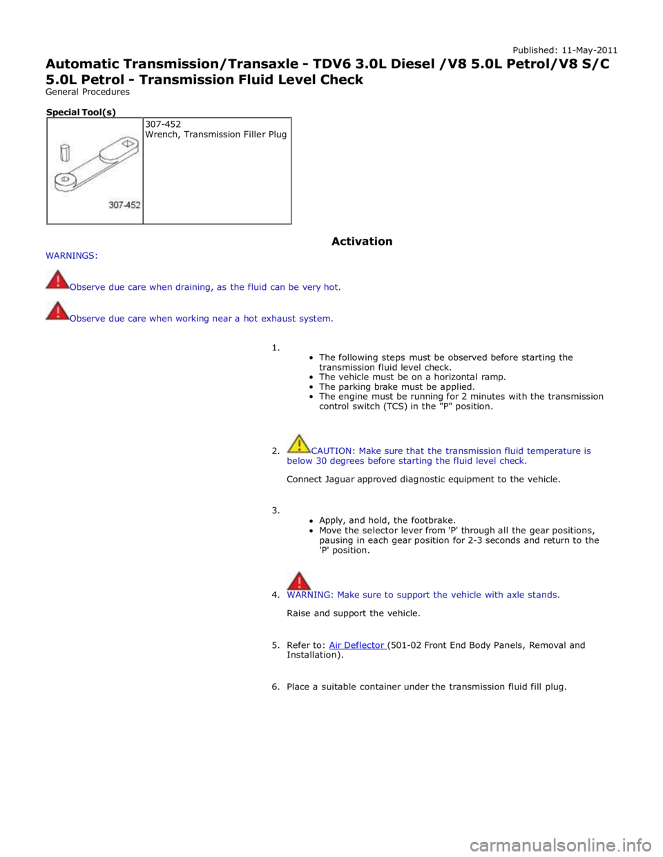
6. Place a suitable container under the transmission fluid fill plug. 307-452
Wrench, Transmission Filler Plug Special Tool(s)
Page 1450 of 3039
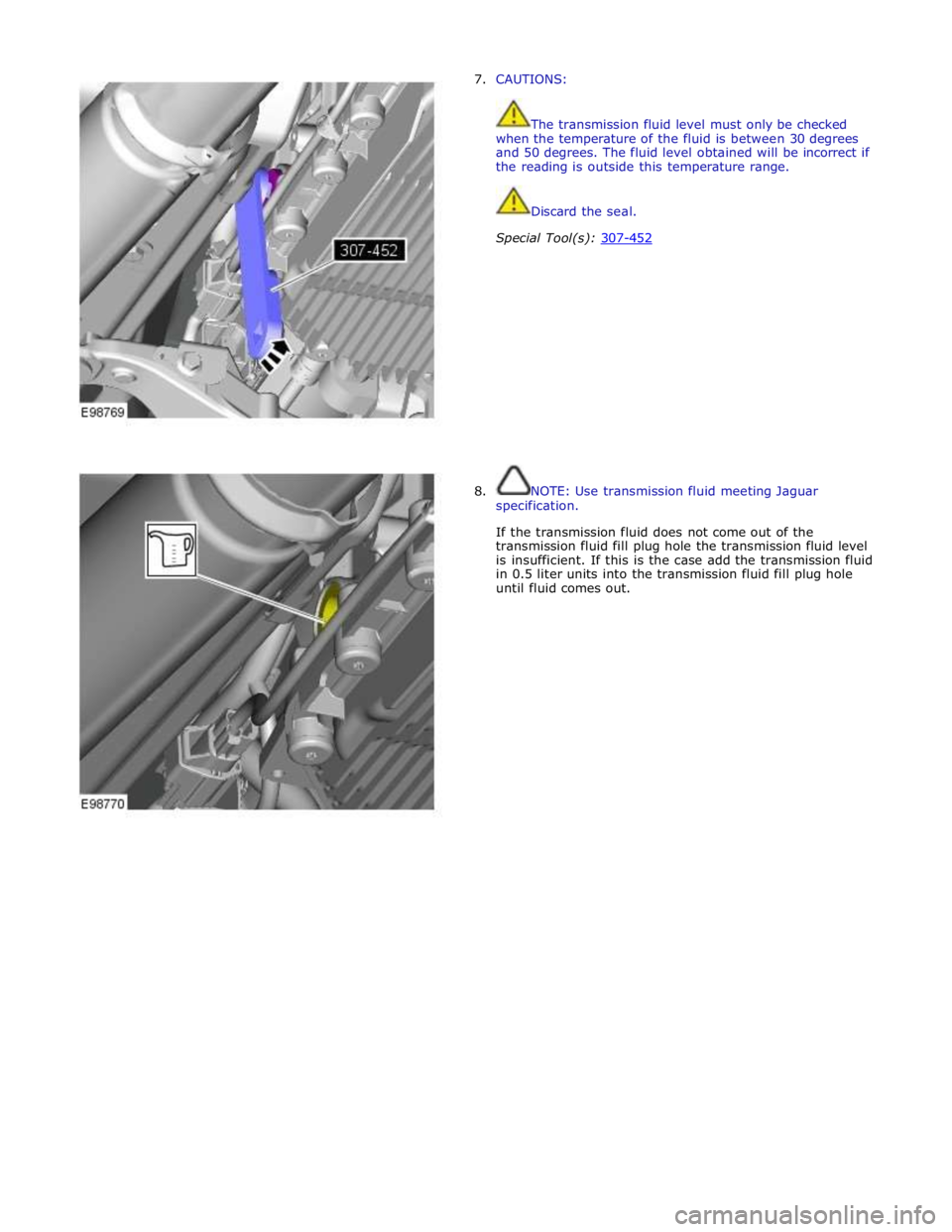
7. CAUTIONS:
The transmission fluid level must only be checked
when the temperature of the fluid is between 30 degrees
and 50 degrees. The fluid level obtained will be incorrect if
the reading is outside this temperature range.
Discard the seal.
Special Tool(s): 307-452
8. NOTE: Use transmission fluid meeting Jaguar
specification.
If the transmission fluid does not come out of the
transmission fluid fill plug hole the transmission fluid level
is insufficient. If this is the case add the transmission fluid
in 0.5 liter units into the transmission fluid fill plug hole
until fluid comes out.
Page 1451 of 3039
9.
10. NOTE: Make sure the transmission fluid temperature
does not exceed 50 °C (122 °F). If the transmission fluid
temperature does exceed 50 °C (122 °F) stop the
transmission fluid level check and allow the transmission
fluid to cool until the temperature is below 30 °C (86 °F).
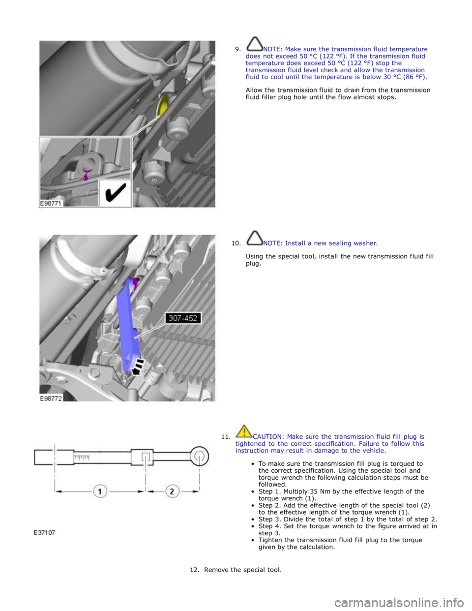
Allow the transmission fluid to drain from the transmission
fluid filler plug hole until the flow almost stops.
NOTE: Install a new sealing washer.
Using the special tool, install the new transmission fluid fill
plug.
11. CAUTION: Make sure the transmission fluid fill plug is
tightened to the correct specification. Failure to follow this
instruction may result in damage to the vehicle.
To make sure the transmission fill plug is torqued to
the correct specification. Using the special tool and
torque wrench the following calculation steps must be
followed.
Step 1. Multiply 35 Nm by the effective length of the
torque wrench (1).
Step 2. Add the effective length of the special tool (2)
to the effective length of the torque wrench (1).
Step 3. Divide the total of step 1 by the total of step 2.
Step 4. Set the torque wrench to the figure arrived at in
step 3.
Tighten the transmission fluid fill plug to the torque
given by the calculation.
12. Remove the special tool.
Page 1453 of 3039
Published: 11-May-2011
Automatic Transmission/Transaxle - TDV6 3.0L Diesel /V8 5.0L Petrol/V8 S/C 5.0L Petrol - Transmission Fluid Drain and Refill
General Procedures
WARNINGS:
Observe due care when draining, as the fluid can be very hot.
Observe due care when working near a hot exhaust system.
1. WARNING: Make sure to support the vehicle with axle stands.
Raise and support the vehicle.
2. Refer to: Air Deflector (501-02 Front End Body Panels, Removal and Installation).
3. Place a container under the transmission.
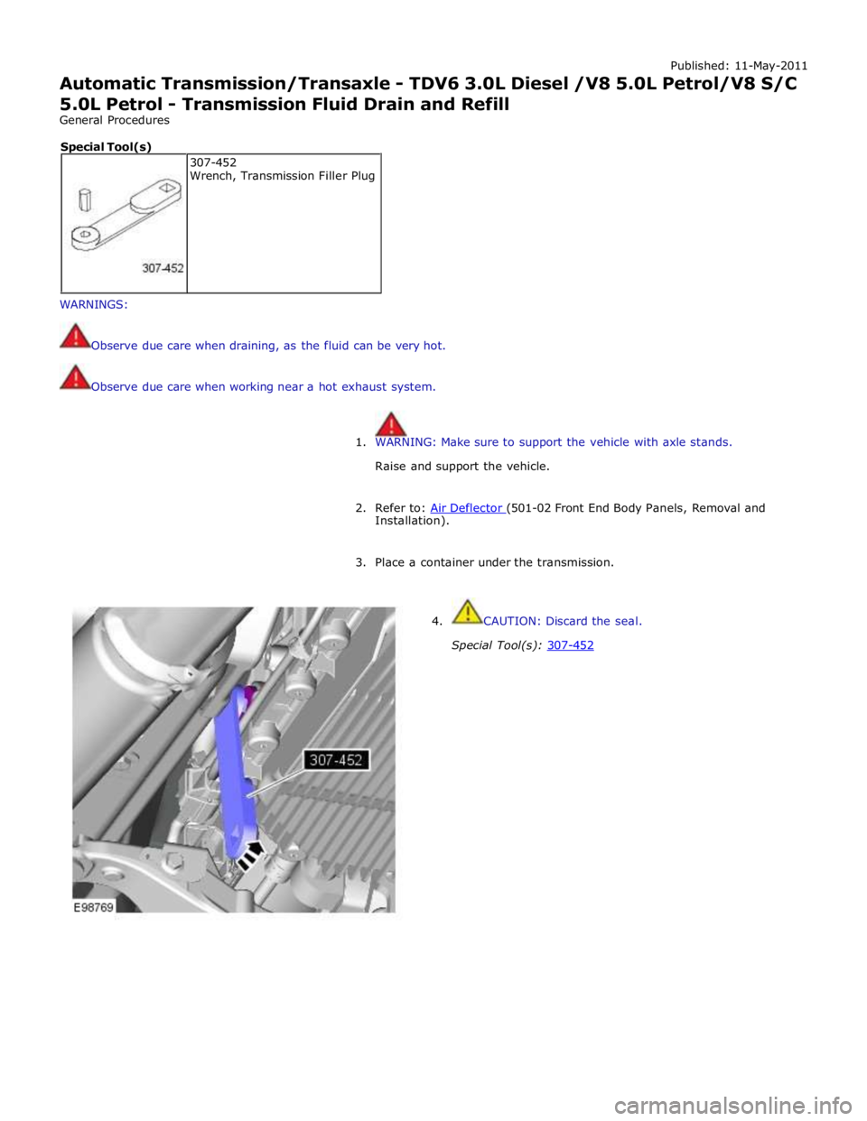
4. CAUTION: Discard the seal.
Special Tool(s): 307-452 307-452
Wrench, Transmission Filler Plug Special Tool(s)
Page 1454 of 3039
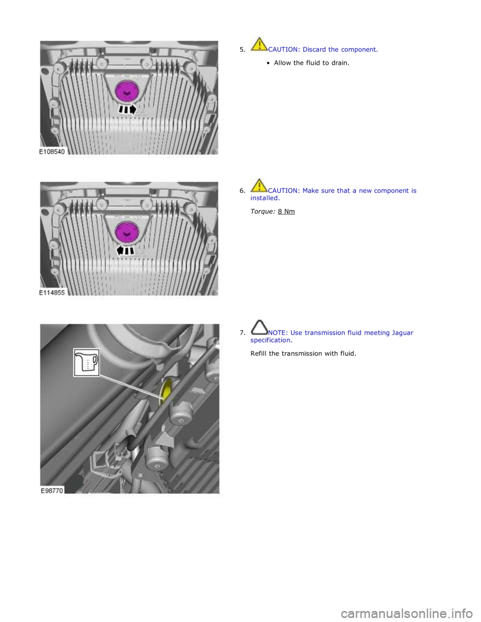
5. CAUTION: Discard the component.
Allow the fluid to drain.
6. CAUTION: Make sure that a new component is
installed.
Torque: 8 Nm
7. NOTE: Use transmission fluid meeting Jaguar
specification.
Refill the transmission with fluid.
Page 1455 of 3039
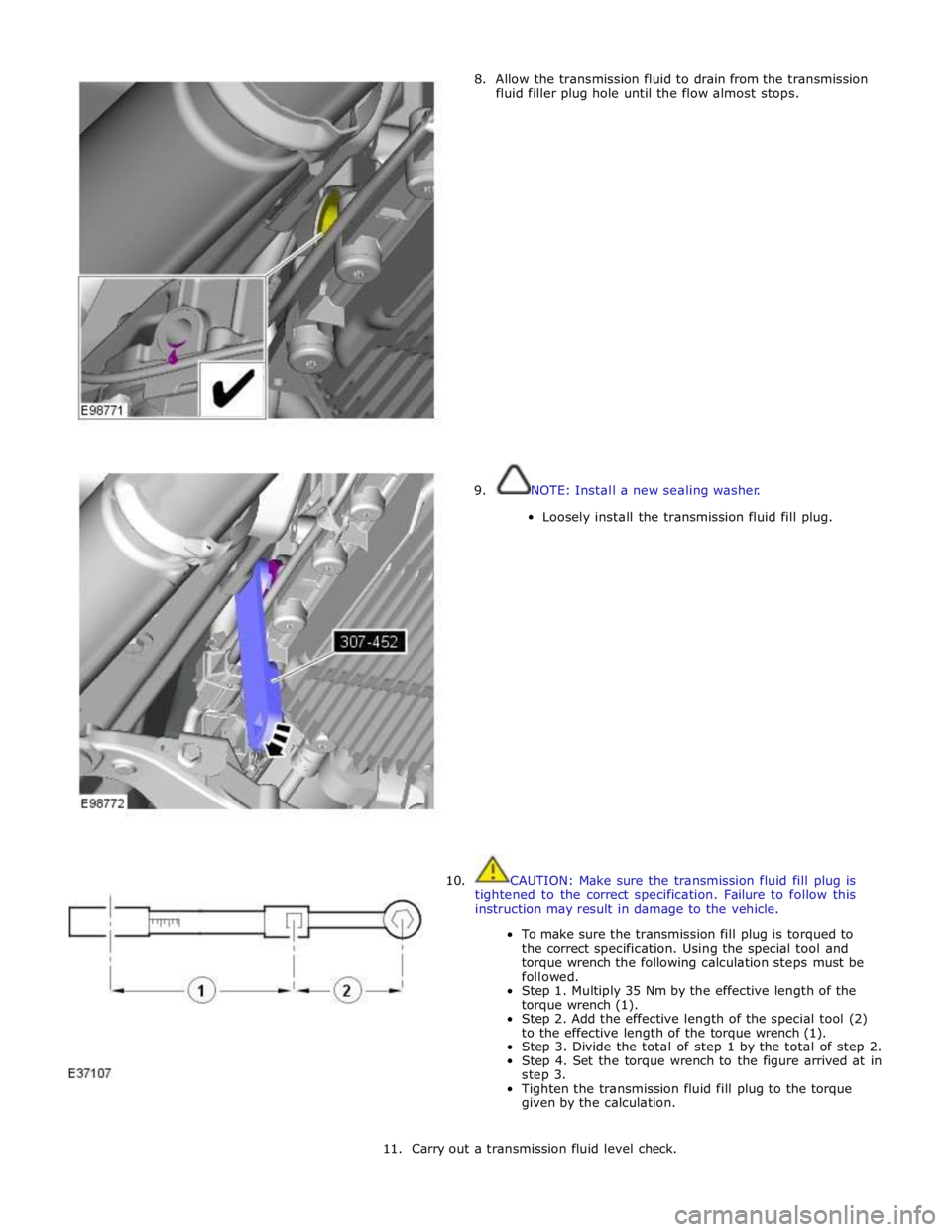
8. Allow the transmission fluid to drain from the transmission
fluid filler plug hole until the flow almost stops.
9. NOTE: Install a new sealing washer.
Loosely install the transmission fluid fill plug.
10. CAUTION: Make sure the transmission fluid fill plug is
tightened to the correct specification. Failure to follow this
instruction may result in damage to the vehicle.
To make sure the transmission fill plug is torqued to
the correct specification. Using the special tool and
torque wrench the following calculation steps must be
followed.
Step 1. Multiply 35 Nm by the effective length of the
torque wrench (1).
Step 2. Add the effective length of the special tool (2)
to the effective length of the torque wrench (1).
Step 3. Divide the total of step 1 by the total of step 2.
Step 4. Set the torque wrench to the figure arrived at in
step 3.
Tighten the transmission fluid fill plug to the torque
given by the calculation.
11. Carry out a transmission fluid level check.