2010 JAGUAR XFR Transmission
[x] Cancel search: TransmissionPage 1371 of 3039

Symptom Possible Cause Action Engine stalls on overrun
ECM relay
Throttle position (TP)
sensors
Read DTCs and refer to DTC Index in this
section for ECM relay and TP sensor tests Engine stalls at steady speed
ECM relay
crankshaft position sensor
TP sensors
Read DTCs and refer to DTC Index in this
section for ECM relay, crankshaft position
sensor, and TP sensor tests Engine stalls with speed control
enabled
ECM relay
Read DTCs and refer to DTC Index in this
section for ECM relay tests Engine stalls when manoeuvring
ECM relay
TP sensors
Additional engine loads
(PAS, air conditioning, etc)
Transmission malfunction
CAN malfunction
Read DTCs and refer to DTC Index in this
section for ECM relay, and TP sensor tests
Check for excessive loads being placed on
the engine from PAS, air conditioning
systems etc.
Refer to the workshop manual or
transmission troubleshooting guide for
transmission system tests.
Refer to the relevant section of the
workshop manual and the electrical wiring
diagrams to perform CAN network tests. Poor driveability Engine hesitates/poor acceleration
Fuel pressure, fuel pump,
fuel lines
Injector leak
Air leakage
Electronic engine controls
Ignition system
EGR valve stuck
Transmission malfunction
Restricted pedal travel
(carpet, etc)
For fuel system tests refer to the relevant
section of the workshop manual
Carry out fuel injector leak tests, install new
injectors as necessary.
Check for leakage from air intake system
Read DTCs and refer to DTC Index in this
section for electronic engine control tests
For ignition system tests refer to the
relevant section of the workshop manual
Refer to the relevant section of the
workshop manual and check the Exhaust Gas
Recirculation (EGR) valve and associated
hoses and connections.
Refer to the workshop manual or
transmission troubleshooting guide for
transmission system tests.
Ensure accelerator pedal is free from
restriction Engine backfires
Fuel pump, fuel lines
Air leakage
Electronic engine controls
Ignition system
Sticking variable camshaft
timing (VCT) hub
For fuel system tests refer to the relevant
section of the workshop manual
Check for leakage from air intake system
Read DTCs and refer to DTC Index in this
section for electronic engine control tests
For ignition system tests refer to the
relevant section of the workshop manual
Read DTCs and refer to DTC Index in this
section for VCT system tests Engine surges
Fuel pump, fuel lines
Electronic engine controls
Ignition system
For fuel system tests refer to the relevant
section of the workshop manual
Read DTCs and refer to DTC Index in this
section for electronic engine control tests
For ignition system tests refer to the
relevant section of the workshop manual Engine detonates/knocks
Electronic engine controls
Fuel pump, fuel lines, fuel
quality
Air leakage
Sticking VCT hub
Read DTCs and refer to DTC Index in this
section for electronic engine control tests
For fuel system tests refer to the relevant
section of the workshop manual
Check for leakage from air intake system
Read DTCs and refer to DTC Index in this
section for VCT system tests www.JagDocs.com
Page 1372 of 3039
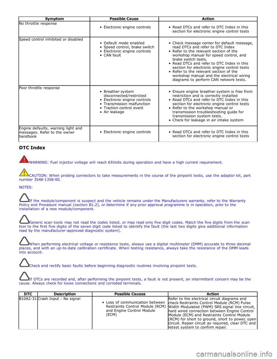
Symptom Possible Cause Action No throttle response
Electronic engine controls
Read DTCs and refer to DTC Index in this
section for electronic engine control tests Speed control inhibited or disabled
Default mode enabled
Speed control, brake switch
Electronic engine controls
CAN fault
Check message center for default message,
read DTCs and refer to DTC Index
Refer to the relevant section of the
workshop manual for speed control, and
brake switch tests.
Read DTCs and refer to DTC Index in this
section for electronic engine control tests
Refer to the relevant section of the
workshop manual and the electrical wiring
diagrams to perform CAN network tests. Poor throttle response
Breather system
disconnected/restricted
Electronic engine controls
Transmission malfunction
Traction control event
Air leakage
Ensure engine breather system is free from
restriction and is correctly installed
Read DTCs and refer to DTC Index in this
section for electronic engine control tests
Refer to the workshop manual or
transmission troubleshooting guide for
transmission system tests.
Check for leakage in air intake system Engine defaults, warning light and
messages. Refer to the owner
handbook
Electronic engine controls
Read DTCs and refer to DTC Index in this
section for electronic engine control tests DTC Index
WARNING: Fuel injector voltage will reach 65Volts during operation and have a high current requirement.
CAUTION: When probing connectors to take measurements in the course of the pinpoint tests, use the adaptor kit, part
number 3548-1358-00.
NOTES:
If the module/component is suspect and the vehicle remains under the Manufacturers warranty, refer to the Warranty
Policy and Procedure manual (section B1.2), or determine if any prior approval programme is in operation, prior to the
installation of a new module/component.
Generic scan tools may not read the codes listed, or may read only five digit codes. Match the five digits from the scan
tool to the first five digits of the seven digit code listed to identify the fault (the last two digits give additional information
read by the manufacturer-approved diagnostic system).
When performing electrical voltage or resistance tests, always use a digital multimeter (DMM) accurate to three decimal
places, and with an up-to-date calibration certificate. When testing resistance, always take the resistance of the DMM leads
into account.
Check and rectify basic faults before beginning diagnostic routines involving pinpoint tests.
If DTCs are recorded and, after performing the pinpoint tests, a fault is not present, an intermittent concern may be the
cause. Always check for loose connections and corroded terminals.
DTC Description Possible Causes Action B10A2-31 Crash Input - No signal
Loss of communication between
Restraints Control Module (RCM)
and Engine Control Module
(ECM) Refer to the electrical circuit diagrams and
check Restraints Control Module (RCM) Pulse
Width Modulated (PWM) SRS signal line circuit,
hard wired connection between Engine Control
Module (ECM) and Restraints Control Module
(RCM) for short to ground, short to power, open
circuit. Repair circuit as required, clear DTC and
retest system to confirm repair.
Page 1408 of 3039
Published: 11-May-2011
Automatic Transmission/Transaxle - TDV6 3.0L Diesel /V8 5.0L Petrol/V8 S/C 5.0L Petrol -
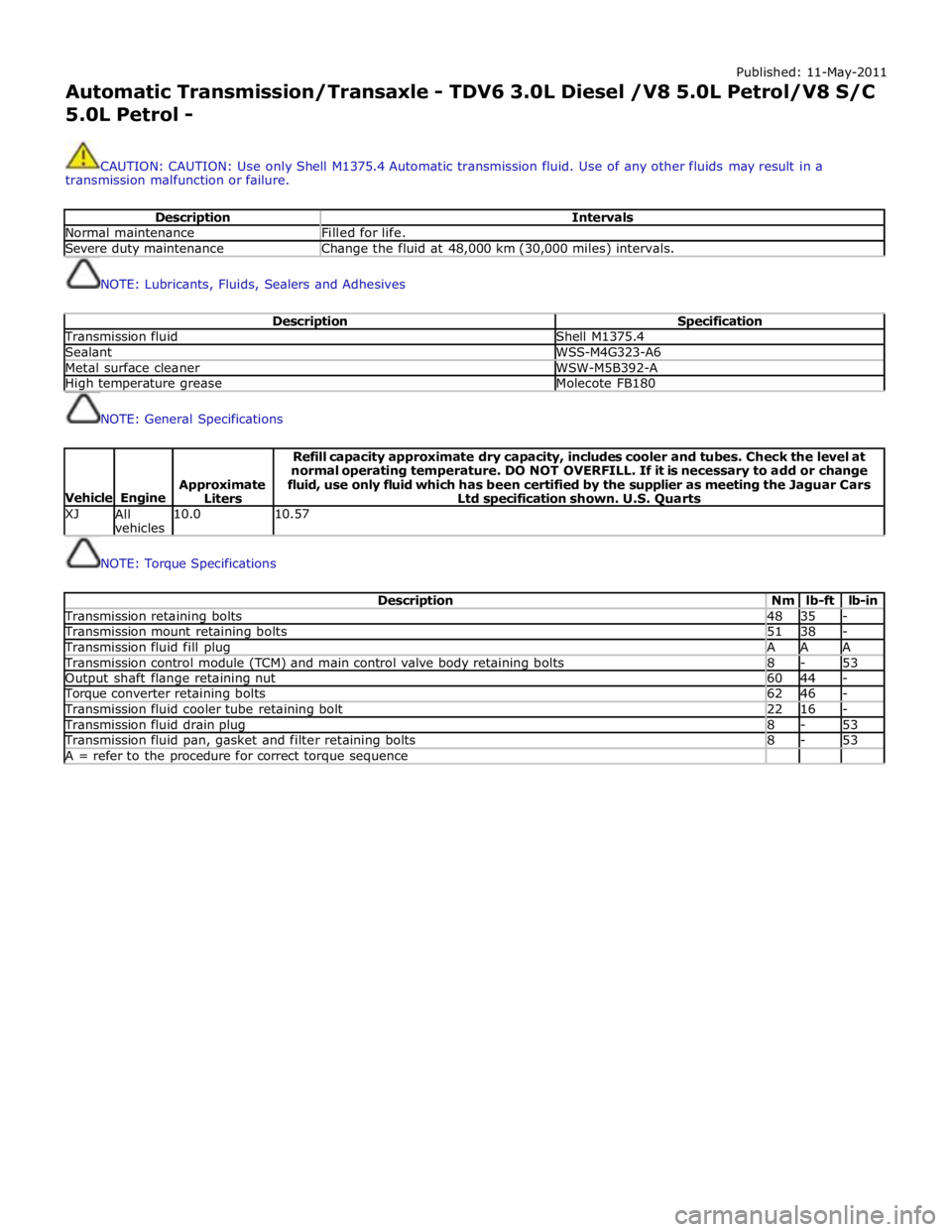
CAUTION: CAUTION: Use only Shell M1375.4 Automatic transmission fluid. Use of any other fluids may result in a
transmission malfunction or failure.
Description Intervals Normal maintenance Filled for life. Severe duty maintenance Change the fluid at 48,000 km (30,000 miles) intervals.
NOTE: Lubricants, Fluids, Sealers and Adhesives
Description Specification Transmission fluid Shell M1375.4 Sealant WSS-M4G323-A6 Metal surface cleaner WSW-M5B392-A High temperature grease Molecote FB180
NOTE: General Specifications
Vehicle
Engine
Approximate
Liters Refill capacity approximate dry capacity, includes cooler and tubes. Check the level at
normal operating temperature. DO NOT OVERFILL. If it is necessary to add or change
fluid, use only fluid which has been certified by the supplier as meeting the Jaguar Cars
Ltd specification shown. U.S. Quarts XJ
All
vehicles 10.0 10.57
NOTE: Torque Specifications
Description Nm lb-ft lb-in Transmission retaining bolts 48 35 - Transmission mount retaining bolts 51 38 - Transmission fluid fill plug A A A Transmission control module (TCM) and main control valve body retaining bolts 8 - 53 Output shaft flange retaining nut 60 44 - Torque converter retaining bolts 62 46 - Transmission fluid cooler tube retaining bolt 22 16 - Transmission fluid drain plug 8 - 53 Transmission fluid pan, gasket and filter retaining bolts 8 - 53 A = refer to the procedure for correct torque sequence
Page 1410 of 3039
Published: 11-May-2011
Automatic Transmission/Transaxle - TDV6 3.0L Diesel /V8 5.0L Petrol/V8 S/C 5.0L Petrol - Transmission Description - Overview
Description and Operation
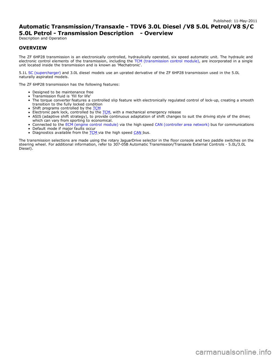
OVERVIEW
The ZF 6HP28 transmission is an electronically controlled, hydraulically operated, six speed automatic unit. The hydraulic and
electronic control elements of the transmission, including the TCM (transmission control module), are incorporated in a single
unit located inside the transmission and is known as 'Mechatronic'.
5.1 L SC (supercharger) and 3.0L diesel models use an uprated derivative of the ZF 6HP28 transmission used in the 5.0L
naturally aspirated models.
The ZF 6HP28 transmission has the following features:
Designed to be maintenance free
Transmission fluid is 'fill for life'
The torque converter features a controlled slip feature with electronically regulated control of lock-up, creating a smooth
transition to the fully locked condition
Shift programs controlled by the TCM Electronic park lock, controlled by the TCM, with a mechanical emergency release ASIS (adaptive shift strategy), to provide continuous adaptation of shift changes to suit the driving style of the driver,
which can vary from sporting to economical.
Connected to the ECM (engine control module) via the high speed CAN (controller area network) bus for communications
Default mode if major faults occur
Diagnostics available from the TCM via the high speed CAN bus.
The transmission selections are made using the rotary JaguarDrive selector in the floor console and two paddle switches on the
steering wheel. For additional information, refer to 307-05B Automatic Transmission/Transaxle External Controls - 5.0L/3.0L
Diesel).
Page 1411 of 3039
Published: 11-May-2011
Automatic Transmission/Transaxle - TDV6 3.0L Diesel /V8 5.0L Petrol/V8 S/C 5.0L Petrol - Transmission Description - System Operation and Component Description
Description and Operation
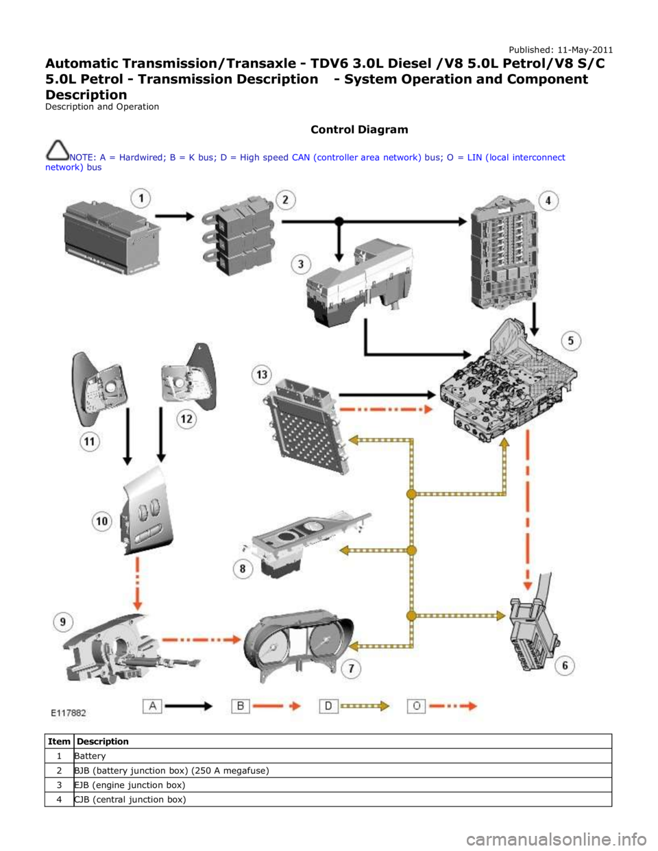
Control Diagram
NOTE: A = Hardwired; B = K bus; D = High speed CAN (controller area network) bus; O = LIN (local interconnect
network) bus
Item Description 1 Battery 2 BJB (battery junction box) (250 A megafuse) 3 EJB (engine junction box) 4 CJB (central junction box)
Page 1412 of 3039
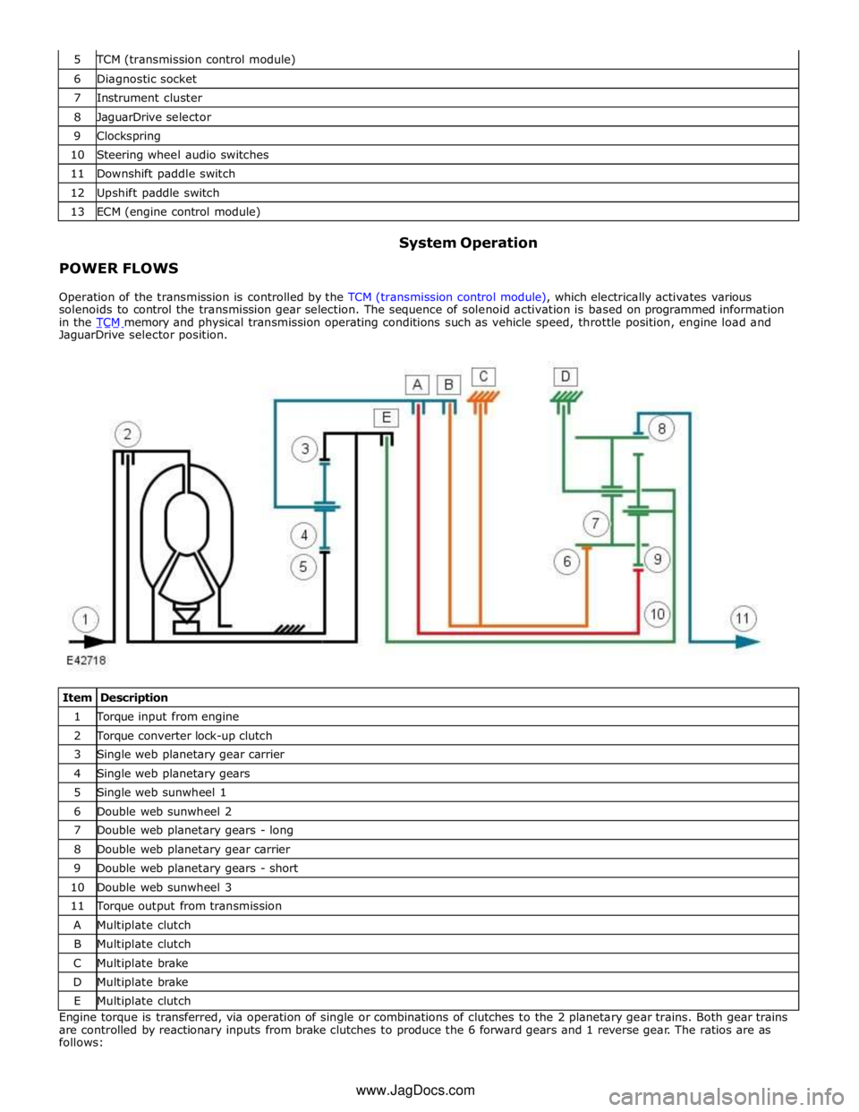
TCM (transmission control module) 6 Diagnostic socket 7 Instrument cluster 8 JaguarDrive selector 9 Clockspring 10 Steering wheel audio switches 11 Downshift paddle switch 12 Upshift paddle switch 13 ECM (engine control module)
POWER FLOWS System Operation
Operation of the transmission is controlled by the TCM (transmission control module), which electrically activates various
solenoids to control the transmission gear selection. The sequence of solenoid activation is based on programmed information
in the TCM memory and physical transmission operating conditions such as vehicle speed, throttle position, engine load and JaguarDrive selector position.
Item Description 1 Torque input from engine 2 Torque converter lock-up clutch 3 Single web planetary gear carrier 4 Single web planetary gears 5 Single web sunwheel 1 6 Double web sunwheel 2 7 Double web planetary gears - long 8 Double web planetary gear carrier 9 Double web planetary gears - short 10 Double web sunwheel 3 11 Torque output from transmission A Multiplate clutch B Multiplate clutch C Multiplate brake D Multiplate brake E Multiplate clutch Engine torque is transferred, via operation of single or combinations of clutches to the 2 planetary gear trains. Both gear trains
are controlled by reactionary inputs from brake clutches to produce the 6 forward gears and 1 reverse gear. The ratios are as
follows: www.JagDocs.com
Page 1413 of 3039
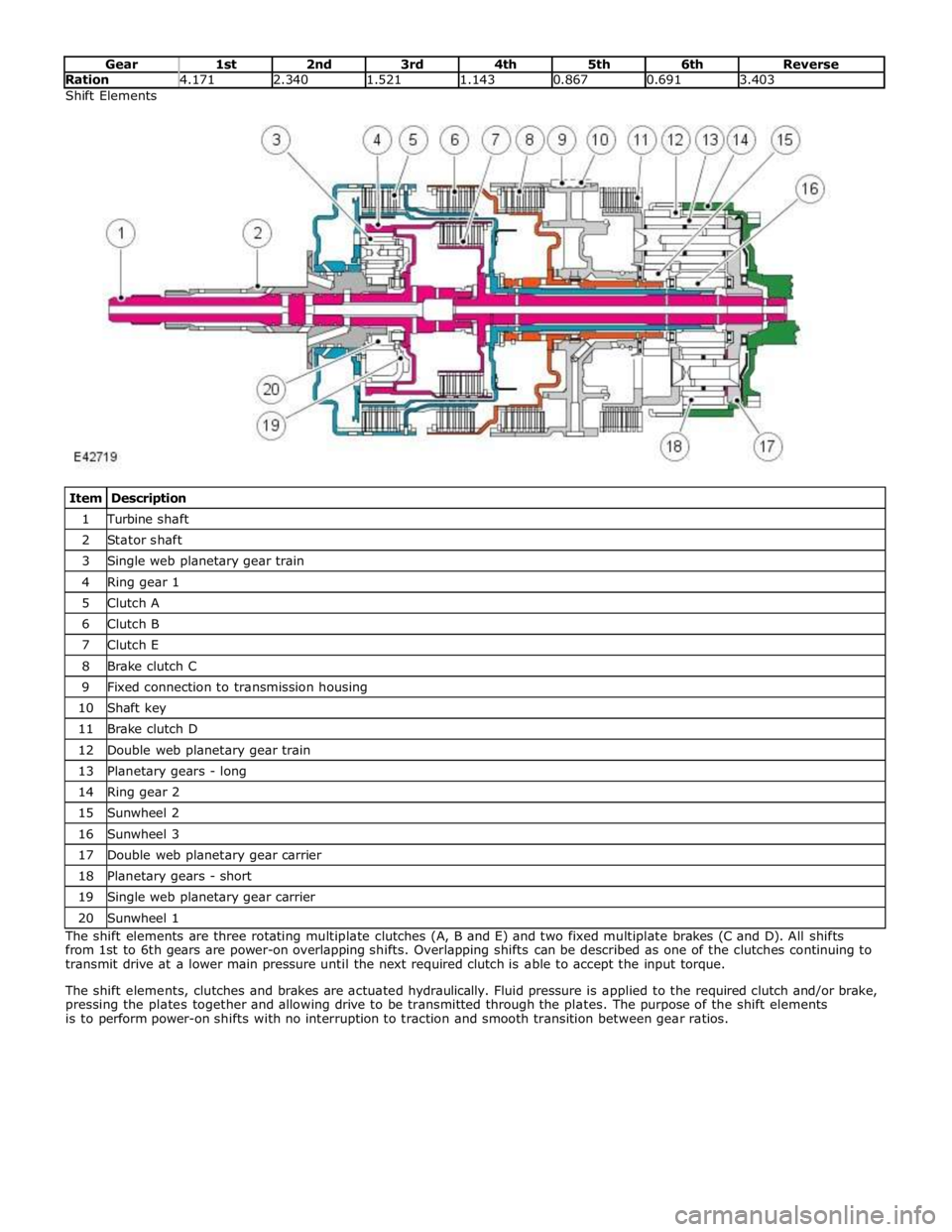
Ration 4.171 2.340 1.521 1.143 0.867 0.691 3.403 Shift Elements
Item Description 1 Turbine shaft 2 Stator shaft 3 Single web planetary gear train 4 Ring gear 1 5 Clutch A 6 Clutch B 7 Clutch E 8 Brake clutch C 9 Fixed connection to transmission housing 10 Shaft key 11 Brake clutch D 12 Double web planetary gear train 13 Planetary gears - long 14 Ring gear 2 15 Sunwheel 2 16 Sunwheel 3 17 Double web planetary gear carrier 18 Planetary gears - short 19 Single web planetary gear carrier 20 Sunwheel 1 The shift elements are three rotating multiplate clutches (A, B and E) and two fixed multiplate brakes (C and D). All shifts
from 1st to 6th gears are power-on overlapping shifts. Overlapping shifts can be described as one of the clutches continuing to
transmit drive at a lower main pressure until the next required clutch is able to accept the input torque.
The shift elements, clutches and brakes are actuated hydraulically. Fluid pressure is applied to the required clutch and/or brake,
pressing the plates together and allowing drive to be transmitted through the plates. The purpose of the shift elements
is to perform power-on shifts with no interruption to traction and smooth transition between gear ratios.
Page 1414 of 3039
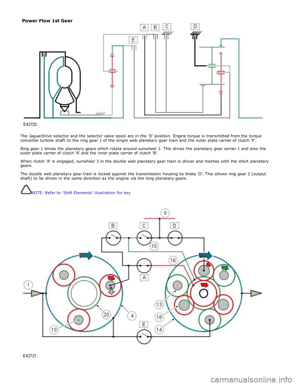
The JaguarDrive selector and the selector valve spool are in the 'D' position. Engine torque is transmitted from the torque
converter turbine shaft to the ring gear 1 of the single web planetary gear train and the outer plate carrier of clutch 'E'.
Ring gear 1 drives the planetary gears which rotate around sunwheel 1. This drives the planetary gear carrier 1 and also the
outer plate carrier of clutch 'A' and the inner plate carrier of clutch 'B'.
When clutch 'A' is engaged, sunwheel 3 in the double web planetary gear train is driven and meshes with the short planetary
gears.
The double web planetary gear train is locked against the transmission housing by brake 'D'. This allows ring gear 2 (output
shaft) to be driven in the same direction as the engine via the long planetary gears.
NOTE: Refer to 'Shift Elements' illustration for key
Power Flow 1st Gear