2010 JAGUAR XFR abs module
[x] Cancel search: abs modulePage 2317 of 3039

memory positions to be stored and 'set' button with integral LED (light emitting diode). The seat, door mirror and steering
column motors have position sensors which provide feedback to driver's seat module.
Once the driver's seat, steering column and exterior mirrors have been adjusted, the vehicle is able to memorize these
settings for future use by using the following procedure:
Push the memory 'SET' button, the LED in the switch will illuminate Press the memory button 1 or 2 to memorize the current settings. The LED will extinguish, and a chime will sound to confirm that the settings have been memorized. If the ignition is on, power mode 6, the message center will display a
confirmation message.
The positions can be recalled by pressing the applicable button 1 or 2.
Stall Detection
Seat, steering column and mirror motors are deemed to have stalled if there is no change in the inputs that are received from
the corresponding feedback sensors for 200 ms (seat).
If a stall condition is detected then the drive to that motor is cancelled for the remainder of that memory operation (memory
recall) or until the switch is re-selected (manual movement).
If the motor movement has stopped due to loss of sensor feedback, either stall or sensor failure, then that motor may be
activated again, to move past the stall position, by re-selecting the appropriate switch and pressing for longer than 2 seconds.
This allows control of the motor to be maintained if sensor feedback is lost.
Upon re-selection of movement, if sensor pulses are detected then the motor will continue to be driven until the switch is
released or another stall condition is detected. If sensor feedback is not detected then the motor is only driven for 0.5 second
and then stops until the switch is released and then pressed again, when a further 0.5 second of activation is permitted, and
so on, this is known as inch mode.
For all seat motor manual movements, whenever a motor is driven and a stall occurs, the memory control module records the
position at which the stall occurred. If movement occurs beyond a stall position, then that position is erased from the control
modules memory. This will always allow movement past a previously recorded stall position once movement has been
registered beyond that position. This is the case for both manual and memory movement.
Initialization
When a replacement driver's seat module is fitted, it should be calibrated a Jaguar approved diagnostic system so that the
module can learn the seats absolute position.
Battery Monitor
If the battery voltage drops below 10.5 Volts, then the driver's seat module ignores all requests for a memory recall until the
battery voltage has reached 11.5 Volts. This will conserve as much power in the vehicle battery as possible to enable engine
cranking.
REAR SEATS - DESCRIPTION
The rear seat features a single piece cushion and a 60/40 split squab. Two latches are secured to the rear bulkhead by a pair
of M8 bolts to retain the seat squabs in the upright position. The latches can be released to fold down the individual cushions
by pulling a cable release located below the rear window parcel shelf in the luggage compartment.
ISOFIX fastening points are attached to the vehicle floor to provide secure fastening for compatible child seats.
A centrally mounted center arm rest can be folded down from the 60% squab. The arm rest contains two drinks holders.
Page 2559 of 3039

Published: 11-May-2011
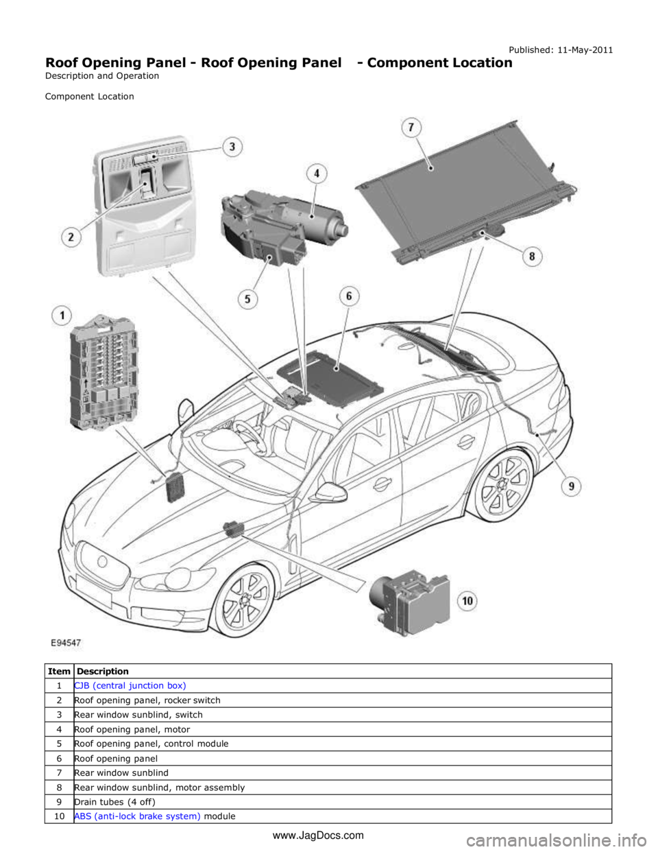
Roof Opening Panel - Roof Opening Panel - Component Location
Description and Operation
Component Location
Item Description 1 CJB (central junction box) 2 Roof opening panel, rocker switch 3 Rear window sunblind, switch 4 Roof opening panel, motor 5 Roof opening panel, control module 6 Roof opening panel 7 Rear window sunblind 8 Rear window sunblind, motor assembly 9 Drain tubes (4 off) 10 ABS (anti-lock brake system) module www.JagDocs.com
Page 2561 of 3039

Published: 11-May-2011
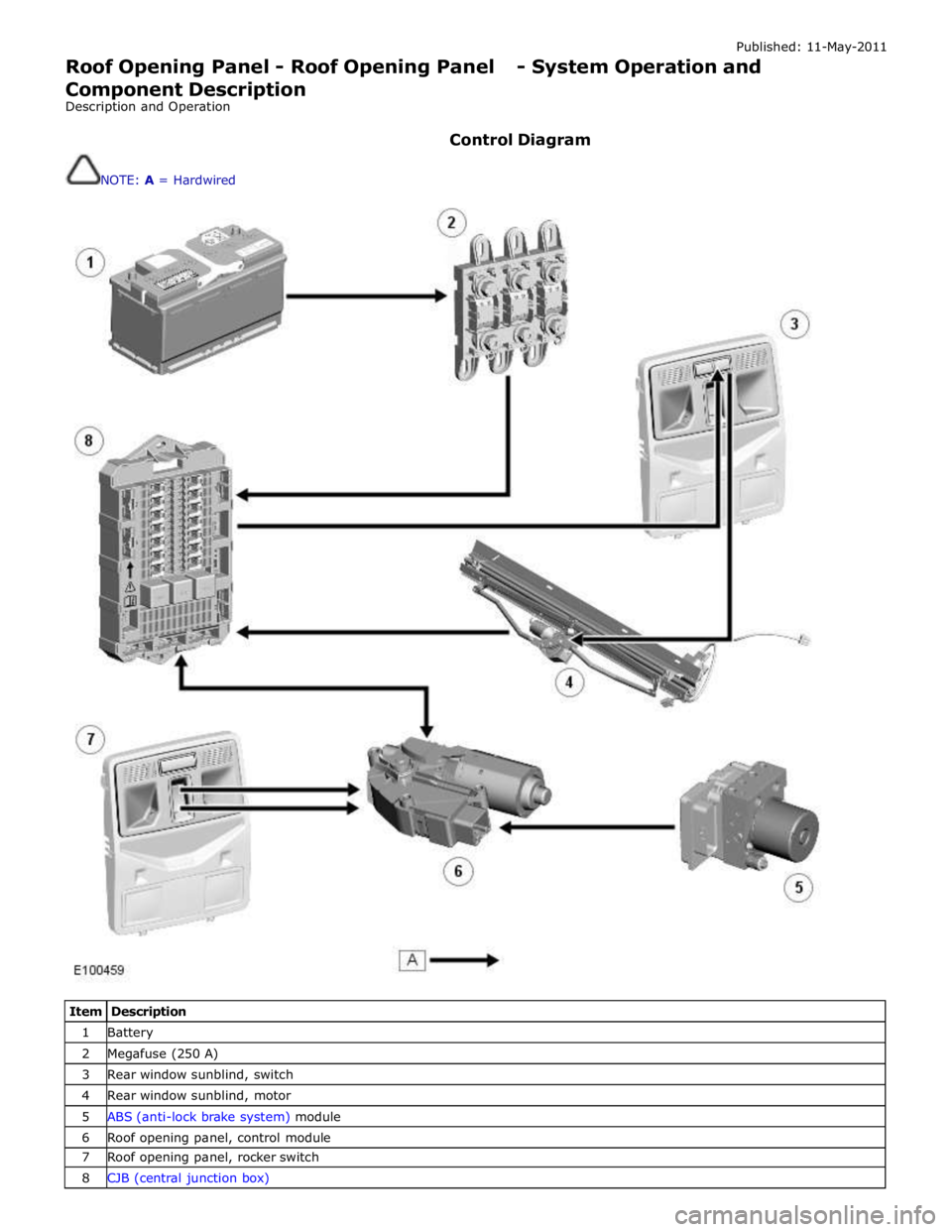
Roof Opening Panel - Roof Opening Panel - System Operation and
Component Description
Description and Operation
Control Diagram
NOTE: A = Hardwired
Item Description 1 Battery 2 Megafuse (250 A) 3 Rear window sunblind, switch 4 Rear window sunblind, motor 5 ABS (anti-lock brake system) module 6 Roof opening panel, control module 7 Roof opening panel, rocker switch 8 CJB (central junction box)
Page 2562 of 3039

Roof opening panel System Operation
Operation of the roof opening panel is controlled by the roof opening panel control module, which is integral with the motor.
The control module receives inputs from the CJB, which provides an 'open' or 'close' signal for remote handset operation, and
an 'enable' signal when the vehicle enters power mode 6.
The control module also receives a vehicle speed signal from the ABS module. The vehicle speed signal is used by the control
module to calibrate the anti-trap feature.
If the battery is disconnected, or the power supply is interrupted while the roof opening panel is in a partially open position,
the motor and control module will need to be calibrated to restore full functionality. To recalibrate:
1. Switch ignition on.
2. Press the front of the switch, so the roof opening panel is the tilt position, and then release the switch.
3. Press the front of the switch and hold for thirty seconds.
4. After thirty seconds the roof opening panel will begin to move. Keep the front of the switch pressed until the roof
opening panel has fully opened and then closed.
5. Once the open/close cycle has completed and the roof opening panel has stopped moving, release the switch.
6. The roof opening panel can now be operated as normal.
Drain hoses are connected to the front and rear corners of the roof opening panel frame. The drain hoses are located inside of
the cabin on the 'A' and 'D' post pillars to allow water, which has collected in the frame, to escape. One-way valves fitted to
the end of each drain hose, prevent the ingress of dirt and moisture.
Rear window sunblind
The powered rear window sunblind is operated through a switch in the roof console. Power to the sunblind motor is provided by
a pair of relays located in the CJB when the vehicle enters power mode 4. The sunblind motor is located beneath the rear parcel
shelf and is supplied as a sealed unit with the sunblind mechanism.
If the battery is disconnected or a replacement sunblind is fitted, the motor will require re-calibrating. To re-calibrate the
motor the sunblind should be powered through two-full cycles of movement.
Roof opening panel, motor Component Description
The roof opening panel motor has a worm drive which drives a gear in the cast housing attached to the end of the motor. The
gear has a small pinion gear attached to the outer part of its spindle. The pinion engages with two cables to form a rack and
pinion drive. Rotation of the motor turns the pinion which in turn drives the cables in the required direction.
The two cables are attached either side of the pinion. One end of each cable is attached to the guide; the opposite end of
each cable is held in position on the pinion by a metal insert in the frame. The cables run in channels, in the panel frame to
the guides. As the panel is closed the cables are pushed through channels in the front of the frame. The displaced cable is
guided into a further two channels in the frame, which protect the cable and prevent it from snagging. The cables
manufactured from rigid spring steel can pull as well as push the panel along the guides.
The motor contains a micro-switch and Hall effect sensor. Signals received from these components enable the control module
to calculate the exact position of the roof opening panel. The Hall effect sensor is also responsible for the operation of the
anti-trap function.
If the anti-trap feature is activated while the roof opening panel is closing, the panel is reversed for 200mm or as far as
possible. The Hall effect sensor, located in the motor, monitors the speed of the motor and if the speed decreases below a set
threshold, indicating an obstruction, the power feed to the motor is reversed so the panel goes back. In an emergency the
anti-trap function can be overridden by holding the switch in the closed position.
Roof opening panel, control module
The roof opening panel control module is integrated within the motor. The control module receives inputs from the CJB, which
provides an 'open' or 'close' signal for remote handset operation, and an 'enable' signal when the vehicle enters power mode 6.
The control module also contains the algorithm for the anti-trap system and receives a vehicle speed signal from the ABS
module. The vehicle speed signal is used by the control module to calibrate the anti-trap feature.