2010 INFINITI QX56 lower link
[x] Cancel search: lower linkPage 909 of 4210
![INFINITI QX56 2010 Factory Service Manual DOOR LOCK AND UNLOCK SWITCHDLK-75
< COMPONENT DIAGNOSIS > [WITH INTELLIGENT KEY SYSTEM]
C
D
E
F
G H
I
J
L
M A
B
DLK
N
O P
Is the inspection result normal?
YES >> Door lock and unlock switch circuit is](/manual-img/42/57032/w960_57032-908.png "INFINITI QX56 2010 Factory Service Manual DOOR LOCK AND UNLOCK SWITCHDLK-75
< COMPONENT DIAGNOSIS > [WITH INTELLIGENT KEY SYSTEM]
C
D
E
F
G H
I
J
L
M A
B
DLK
N
O P
Is the inspection result normal?
YES >> Door lock and unlock switch circuit is")
DOOR LOCK AND UNLOCK SWITCHDLK-75
< COMPONENT DIAGNOSIS > [WITH INTELLIGENT KEY SYSTEM]
C
D
E
F
G H
I
J
L
M A
B
DLK
N
O P
Is the inspection result normal?
YES >> Door lock and unlock switch circuit is OK.
NO >> GO TO 2
2.CHECK BCM OUTPUT SIGNAL
1. Turn ignition switch OFF.
2. Using the vehicle operational Intelligent Key, pr ess and hold the UNLOCK button for more than 3 sec-
onds.
Is the inspection result normal?
YES >> GO TO 3
NO >> Replace BCM. Refer to BCS-59, "
Removal and Installation".
3.CHECK DOOR LOCK/UNLOCK SWITCH GROUND HARNESS
1. Disconnect main power window and door lock/unlock switch.
2. Check continuity between main power window and door lock/ unlock switch connector D8 terminal 17 and ground.
Is the inspection result normal?
YES >> GO TO 4
NO >> Repair or replace harness.
4.CHECK POWER WINDOW SERIAL LINK CIRCUIT
1. Disconnect BCM.
2. Check continuity between BCM connector M18 term inal 22 and main power window and door lock/unlock
switch connector D7 terminal 14.
Connector Te r m i n a l
Voltage (V)
( + ) ( – )
M18 22 Ground
PIIA6379EPIIA1297E
The front windows should be lowered.
17 - Ground : Continuity should exist.
LIIA0392E
Revision: April 20092010 QX56
Page 1386 of 4210
![INFINITI QX56 2010 Factory Service Manual AUTOMATIC SPEED CONTROL DEVICE (ASCD)EC-33
< FUNCTION DIAGNOSIS > [VK56DE]
C
D
E
F
G H
I
J
K L
M A
EC
NP
O
AUTOMATIC SPEED CONTROL DEVICE (ASCD)
System DescriptionINFOID:0000000005149068
INPUT/OUTPUT](/manual-img/42/57032/w960_57032-1385.png "INFINITI QX56 2010 Factory Service Manual AUTOMATIC SPEED CONTROL DEVICE (ASCD)EC-33
< FUNCTION DIAGNOSIS > [VK56DE]
C
D
E
F
G H
I
J
K L
M A
EC
NP
O
AUTOMATIC SPEED CONTROL DEVICE (ASCD)
System DescriptionINFOID:0000000005149068
INPUT/OUTPUT")
AUTOMATIC SPEED CONTROL DEVICE (ASCD)EC-33
< FUNCTION DIAGNOSIS > [VK56DE]
C
D
E
F
G H
I
J
K L
M A
EC
NP
O
AUTOMATIC SPEED CONTROL DEVICE (ASCD)
System DescriptionINFOID:0000000005149068
INPUT/OUTPUT SIGNAL CHART
*: This signal is sent to the ECM through CAN communication line
BASIC ASCD SYSTEM
Refer to Owner's Manual for ASCD operating instructions.
Automatic Speed Control Device (ASCD) allows a driver to keep vehicle at predetermined constant speed
without depressing accelerator pedal. Driver can set
vehicle speed in advance between approximately 40 km/
h (25 MPH) and 144 km/h (89 MPH).
ECM controls throttle angle of electric thro ttle control actuator to regulate engine speed.
Operation status of ASCD is indicated by CRUISE i ndicator and SET indicator in combination meter. If any
malfunction occurs in ASCD system, it automatically deactivates control.
NOTE:
Always drive vehicle in safe manner according to traffic conditions and obey all traffic laws.
SET OPERATION
Press MAIN switch. (The CRUISE indicato r in combination meter illuminates.)
When vehicle speed reaches a desired speed between approximately 40 km/h (25 MPH) and 144 km/h (89
MPH), press SET/COAST switch. (Then SET indicator in combination meter illuminates.)
ACCELERATE OPERATION
If the RESUME/ACCELERATE switch is pressed during cr uise control driving, increase the vehicle speed until
the switch is released or vehicle speed reac hes maximum speed controlled by the system.
And then ASCD will keep the new set speed.
CANCEL OPERATION
When any of following conditions exis t, cruise operation will be canceled.
• CANCEL switch is pressed
• More than 2 switches at ASCD steer ing switch are pressed at the same time (Set speed will be cleared)
• Brake pedal is depressed
• Selector lever is changed to N, P, R position
• Vehicle speed decreased to 13 km/h (8 MPH) lower than the set speed
• VDC system is operated
When the ECM detects any of the following conditions, the ECM will cancel the cruise operation and inform
the driver by blinking indicator lamp.
• Engine coolant temperature is slightly higher than the normal operating temperature, CRUISE indicator may
blink slowly.
When the engine coolant temperature decreases to the normal operating temperature, CRUISE indicator will
stop blinking and the cruise operation will be able to work by pressing SET/COAST switch or RESUME/
ACCELERATE switch.
• Malfunction for some self-diagnoses regarding ASCD control: SET indicator will blink quickly.
If MAIN switch is turned to OFF during ASCD is activated, all of ASCD operations will be canceled and vehicle
speed memory will be erased.
COAST OPERATION
When the SET/COAST switch is pressed during cruise control driving, decrease vehicle set speed until the
switch is released. And then ASCD will keep the new set speed.
RESUME OPERATION
Sensor Input signal to ECM ECM functionActuator
ASCD brake switch Brake pedal operation
ASCD vehicle speed controlElectric throttle control
actuator
Stop lamp switch
Brake pedal operation
ASCD steering switch ASCD steering switch operation
Wheel sensor Vehicle speed*
TCM Gear position
Powertrain revolution*
Revision: April 20092010 QX56
Page 2175 of 4210
DRIVE SHAFTFAX-9
< REMOVAL AND INSTALLATION >
CEF
G H
I
J
K L
M A
B
FA X
N
O P
DRIVE SHAFT
Removal and InstallationINFOID:0000000005148945
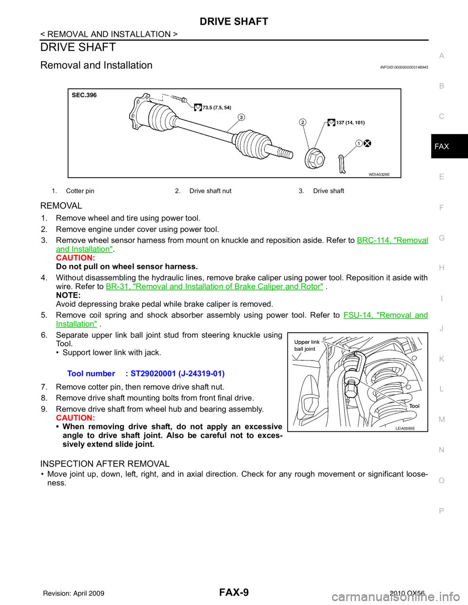
REMOVAL
1. Remove wheel and tire using power tool.
2. Remove engine under cover using power tool.
3. Remove wheel sensor harness from mount on knuckle and reposition aside. Refer to BRC-114, "
Removal
and Installation".
CAUTION:
Do not pull on wheel sensor harness.
4. Without disassembling the hydraulic lines, remove brake caliper using power tool. Reposition it aside with wire. Refer to BR-31, "
Removal and Installation of Brake Caliper and Rotor" .
NOTE:
Avoid depressing brake pedal while brake caliper is removed.
5. Remove coil spring and shock absorber assembly using power tool. Refer to FSU-14, "
Removal and
Installation" .
6. Separate upper link ball joint stud from steering knuckle using Tool.
• Support lower link with jack.
7. Remove cotter pin, then remove drive shaft nut.
8. Remove drive shaft mounting bolts from front final drive.
9. Remove drive shaft from wheel hub and bearing assembly. CAUTION:
• When removing drive shaf t, do not apply an excessive
angle to drive shaft joint. Also be careful not to exces-
sively extend slide joint.
INSPECTION AFTER REMOVAL
• Move joint up, down, left, right, and in axial directi on. Check for any rough movement or significant loose-
ness.
1. Cotter pin 2. Drive shaft nut3. Drive shaft
WDIA0329E
Tool number : ST29020001 (J-24319-01)
LEIA0095E
Revision: April 20092010 QX56
Page 2200 of 4210

FSU-1
SUSPENSION
C
DF
G H
I
J
K L
M
SECTION FSU
A
B
FSU
N
O PCONTENTS
FRONT SUSPENSION
PRECAUTION ....... ........................................2
PRECAUTIONS .............................................. .....2
Precaution for Supplemental Restraint System
(SRS) "AIR BAG" and "SEAT BELT PRE-TEN-
SIONER" ............................................................. ......
2
Precaution Necessary for Steering Wheel Rota-
tion After Battery Disconnect ............................... ......
2
Precaution .................................................................3
PREPARATION ............................................4
PREPARATION .............................................. .....4
Special Service Tool ........................................... ......4
Commercial Service Tool ..........................................4
SYMPTOM DIAGNOSIS ...............................5
NOISE, VIBRATION AND HARSHNESS
(NVH) TROUBLESHOOTING ........................ .....
5
NVH Troubleshooting Chart ................................ ......5
ON-VEHICLE MAINTENANCE .....................6
ON-VEHICLE SERVICE ................................. .....6
Front Suspension Parts ....................................... ......6
Front Wheel Alignment ..............................................6
UPPER BALL JOINT AND LOWER BALL
JOINT .................................................................
10
Inspection ............................................................ ....10
KNUCKLE ...................................................... ....12
On-Vehicle Inspection and Service ..................... ....12
ON-VEHICLE REPAIR .................................13
FRONT SUSPENSION ASSEMBLY .............. ....13
Component .......................................................... ....13
REMOVAL AND INSTALLATION ...............14
COIL SPRING AND SHOCK ABSORBER .......14
Removal and Installation ..................................... ....14
Disposal ...................................................................14
STABILIZER BAR .............................................15
Removal and Installation .........................................15
UPPER LINK .....................................................16
Removal and Installation ..................................... ....16
LOWER LINK ....................................................17
Removal and Installation .........................................17
UPPER BALL JOINT AND LOWER BALL
JOINT ................................................................
18
Removal and Installation .........................................18
KNUCKLE .........................................................19
Removal and Installation ..................................... ....19
DISASSEMBLY AND ASSEMBLY ..............21
COIL SPRING AND SHOCK ABSORBER .......21
Disassembly and Assembly ................................. ....21
SERVICE DATA AND SPECIFICATIONS
(SDS) ............... .......................................... ...
23
SERVICE DATA AND SPECIFICATIONS
(SDS) .................................................................
23
General Specification .......................................... ....23
Spring Free Height ..................................................23
Wheel Alignment (Unladen*1) ..................................23
Ball Joint .............................................................. ....24
Wheelarch Height (Unladen*1) ................................24
Revision: April 20092010 QX56
Page 2206 of 4210
ON-VEHICLE SERVICEFSU-7
< ON-VEHICLE MAINTENANCE >
C
DF
G H
I
J
K L
M A
B
FSU
N
O P
2. Make sure the alignment machine is properly calibrated. • Your alignment machine should be regularly calibrated in order to give correct information.
• Check with the manufacturer of your specific a lignment machine for their recommended Service/Cali-
bration Schedule.
THE ALIGNMENT PROCESS
IMPORTANT: Use only the alignment specifications listed in this Service Manual. Refer to FSU-23, "Wheel
Alignment (Unladen*1)" .
1. When displaying the alignment settings, many alignm ent machines use “indicators”: (Green/red, plus or
minus, Go/No Go). Do NOT use these indicators.
• The alignment specifications programmed into your alignment machine that operate these indicators may not be correct.
• This may result in an ERROR.
2. Some newer alignment machines are equipped with an optional “Rolling Compensation” method to “com-
pensate” the sensors (alignment targets or head units). Do NOT use this “Rolling Compensation”
method.
• Use the “Jacking Compensation” method. After installing the alignment targets or head units, raise the vehicle and rotate the wheels 1/2 turn both ways.
• See Instructions in the alignment machine you are using for more information.
CAMBER AND CASTER
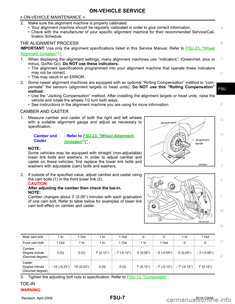
1. Measure camber and caster of both the right and left wheels with a suitable alignment gauge and adjust as necessary to
specification.
NOTE:
Some vehicles may be equipped with straight (non-adjustable)
lower link bolts and washers. In order to adjust camber and
caster on these vehicles, first replace the lower link bolts and
washers with adjustable (cam) bolts and washers.
2. If outside of the specified value, adjust camber and caster using the cam bolts (1) in the front lower link (2).
CAUTION:
After adjusting the camber then check the toe-in.
NOTE:
Camber changes about 3' (0.05 °) minutes with each graduation
of one cam bolt. Refer to table below for examples of lower link
cam bolt effect on camber and caster.
3. Tighten the adjusting bolt nuts to specification. Refer to FSU-13, "
Component" .
TOE-IN
WARNING:Camber and
Caster
: Refer to
FSU-23, "
Wheel Alignment
(Unladen*1)" .
SRA096A
WEIA0153E
Rear cam bolt 1 In 1 Out 1 In 1 Out 0 01 In 1 Out
Front cam bolt 1 Out 1 In 1 In 1 Out 1 In 1 Out 0 0
Camber
Degree minute
(Decimal degree) 0 (0) 0 (0) 7' (0.12
°) - 7' (-0.12 °)3' (0.05 °) - 3' (-0.05 °)3' (0.05 °) - 3' (-0.05 °)
Caster
Degree minute
(Decimal degree) - 14' (-0.23
°)14' (0.23 °) 0 (0) 0 (0) 7' (0.12° ) - 7' (-0.12°) - 7' (-0.12 °)7' (0.12 °)
Revision: April 20092010 QX56
Page 2209 of 4210
FSU-10
< ON-VEHICLE MAINTENANCE >
UPPER BALL JOINT AND LOWER BALL JOINT
UPPER BALL JOINT AND LOWER BALL JOINT
InspectionINFOID:0000000005148110
• Check the ball joint for excessive play. Replace the upper or lower link assembly if any of the followingexists:
- Ball joint stud is worn.
- Ball joint is hard to swing.
- Ball joint play in axial directions or end play is excessive.
Swinging Force
NOTE:
Before checking the axial forces and end play, turn the lower ball joint at least 10 revolutions so that the ball
joint is properly broken in.
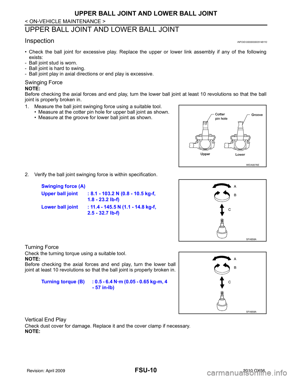
1. Measure the ball joint swinging force using a suitable tool.
• Measure at the cotter pin hole for upper ball joint as shown.
• Measure at the groove for lower ball joint as shown.
2. Verify the ball joint swinging force is within specification.
Turning Force
Check the turning torque using a suitable tool.
NOTE:
Before checking the axial forces and end play, turn the lower ball
joint at least 10 revolutions so that the ball joint is properly broken in.
Vertical End Play
Check dust cover for damage. Replace it and the cover clamp if necessary.
NOTE:
WEIA0076E
Swinging force (A)
Upper ball joint : 8.1 - 103.2 N (0.8 - 10.5 kg-f, 1.8 - 23.2 lb-f)
Lower ball joint : 11.4 - 145.5 N (1.1 - 14.8 kg-f, 2.5 - 32.7 lb-f)
SFA858A
Turning torque (B) : 0.5 - 6.4 N·m (0.05 - 0.65 kg-m, 4 - 57 in-lb)
SFA858A
Revision: April 20092010 QX56
Page 2212 of 4210
FRONT SUSPENSION ASSEMBLYFSU-13
< ON-VEHICLE REPAIR >
C
DF
G H
I
J
K L
M A
B
FSU
N
O P
ON-VEHICLE REPAIR
FRONT SUSPENSION ASSEMBLY
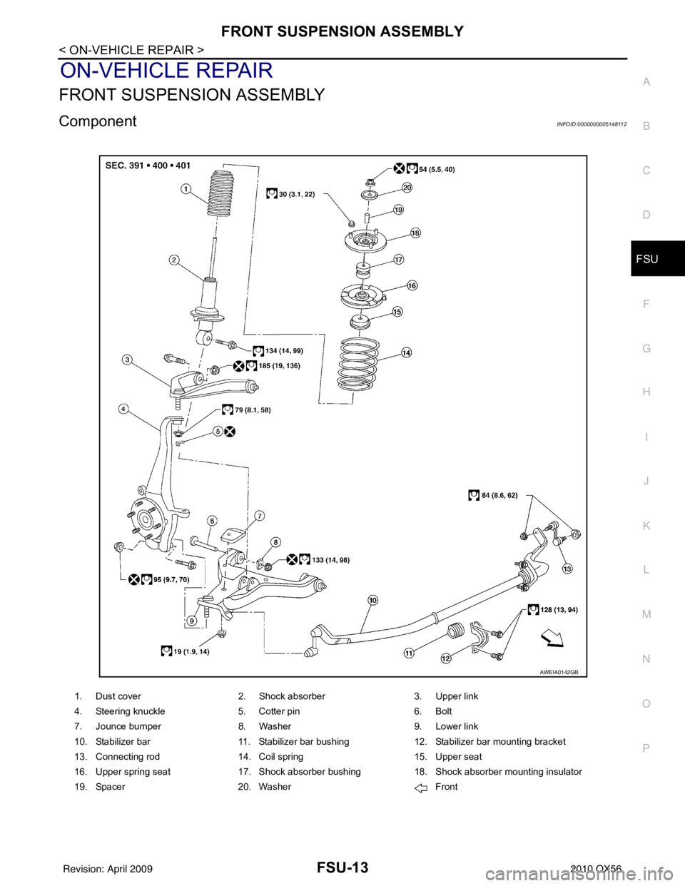
ComponentINFOID:0000000005148112
1. Dust cover 2. Shock absorber 3. Upper link
4. Steering knuckle 5. Cotter pin 6. Bolt
7. Jounce bumper 8. Washer 9. Lower link
10. Stabilizer bar 11. Stabilizer bar bushing 12. Stabilizer bar mounting bracket
13. Connecting rod 14. Coil spring 15. Upper seat
16. Upper spring seat 17. Shock absorber bushing 18. Shock absorber mounting insulator
19. Spacer 20. Washer Front
AWEIA0142GB
Revision: April 20092010 QX56
Page 2215 of 4210
FSU-16
< REMOVAL AND INSTALLATION >
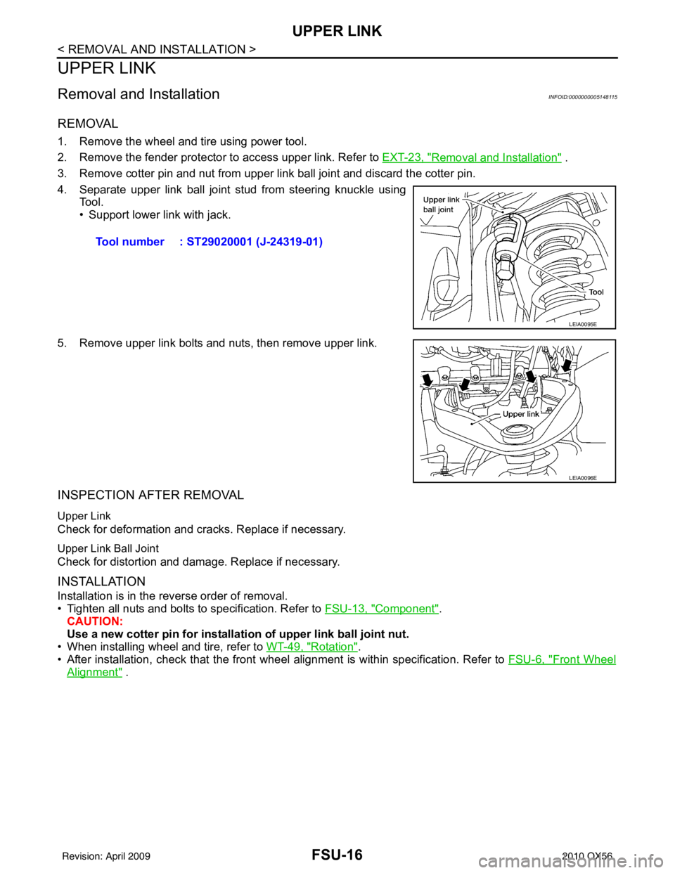
UPPER LINK
UPPER LINK
Removal and InstallationINFOID:0000000005148115
REMOVAL
1. Remove the wheel and tire using power tool.
2. Remove the fender protector to access upper link. Refer to EXT-23, "
Removal and Installation" .
3. Remove cotter pin and nut from upper link ball joint and discard the cotter pin.
4. Separate upper link ball joint stud from steering knuckle using Tool.
• Support lower link with jack.
5. Remove upper link bolts and nuts, then remove upper link.
INSPECTION AFTER REMOVAL
Upper Link
Check for deformation and cracks. Replace if necessary.
Upper Link Ball Joint
Check for distortion and damage. Replace if necessary.
INSTALLATION
Installation is in the reverse order of removal.
• Tighten all nuts and bolts to specification. Refer to FSU-13, "
Component".
CAUTION:
Use a new cotter pin for installation of upper link ball joint nut.
• When installing wheel and tire, refer to WT-49, "
Rotation".
• After installation, check that the front wheel alignment is within specification. Refer to FSU-6, "
Front Wheel
Alignment" .
Tool number : ST29020001 (J-24319-01)
LEIA0095E
LEIA0096E
Revision: April 20092010 QX56